User login
Office-Based Rapid Prototyping in Orthopedic Surgery: A Novel Planning Technique and Review of the Literature
Three-dimensional (3-D) printing is a rapidly evolving technology with both medical and nonmedical applications.1,2 Rapid prototyping involves creating a physical model of human tissue from a 3-D computer-generated rendering.3 The method relies on export of Digital Imaging and Communications in Medicine (DICOM)–based computed tomography (CT) or magnetic resonance imaging (MRI) data into standard triangular language (STL) format. Reducing CT or MRI slice thickness increases resolution of the final model.2 Five types of rapid prototyping exist: STL, selective laser sintering, fused deposition modeling, multijet modeling, and 3-D printing.
Most implant manufacturers can produce a 3-D model based on surgeon-provided DICOM images. The ability to produce anatomical models in an office-based setting is a more recent development. Three-dimensional modeling may allow for more accurate and extensive preoperative planning than radiographic examination alone does, and may even allow surgeons to perform procedures as part of preoperative preparation. This can allow for early recognition of unanticipated intraoperative problems or of the need for special techniques and implants that would not have been otherwise available, all of which may ultimately reduce operative time.
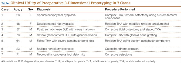
The breadth of applications for office-based 3-D prototyping is not well described in the orthopedic surgery literature. In this article, we describe 7 cases of complex orthopedic disorders that were surgically treated after preoperative planning in which use of a 3-D printer allowed for “mock” surgery before the actual procedures. In 3 of the cases, the models were made by the implant manufacturers. Working with these models prompted us to buy a 3-D printer (Fortus 250; Stratasys, Eden Prairie, Minnesota) for in-office use. In the other 4 cases, we used this printer to create our own models. As indicated in the manufacturer’s literature, the printer uses fused deposition modeling, which builds a model layer by layer by heating thermoplastic material to a semi-liquid state and extruding it according to computer-controlled pathways.
We present preoperative images, preoperative 3-D modeling, and intraoperative and postoperative images along with brief case descriptions (Table). The patients provided written informed consent for print and electronic publication of these case reports.
Case Reports
Case 1
A 28-year-old woman with a history of spondyloepiphyseal dysplasia presented to our clinic with bilateral hip pain. About 8 years earlier, she had undergone bilateral proximal and distal femoral osteotomies. Her function had initially improved, but over the 2 to 3 years before presentation she began having more pain and stiffness with activity. At time of initial evaluation, she was able to walk only 1 to 2 blocks and had difficulty getting in and out of a car and up out of a seated position.
On physical examination, the patient was 3 feet 10 inches tall and weighed 77 pounds. She ambulated with decreased stance phase on both lower extremities and had developed a significant amount of increased forward pelvic inclination and increased lumbar lordosis. Both hips and thighs had multiple healed scars from prior surgeries and pin tracts. Range of motion (ROM) on both sides was restricted to 85° of flexion, 10° of internal rotation, 15° of external rotation, and 15° of abduction.
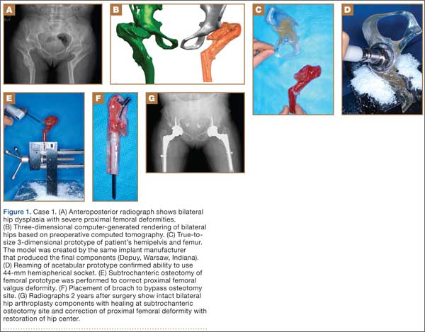
Plain radiographs showed advanced degenerative joint disease (DJD) of both hips with dysplastic acetabuli and evidence of healed osteotomies (Figure 1). Femoral deformities, noted bilaterally, consisted of marked valgus proximally and varus distally. Preoperative CT was used to create a 3-D model of the pelvis and femur. The model was created by the same implant manufacturer that produced the final components (Depuy, Warsaw, Indiana). Corrective femoral osteotomy was performed on the model to allow for design and use of a custom implant, while the modeled pelvis confirmed the ability to reproduce the normal hip center with a 44-mm conventional hemispherical socket.
After surgery, the patient was able to ambulate without a limp and return to work. Her hip ROM was pain-free passively and actively with flexion to 100°, internal rotation to 35°, external rotation to 20°, and abduction to 30°.
Case 2
A 48-year-old woman with a history of Crowe IV hip dysplasia presented to our clinic with a chronically dislocated right total hip arthroplasty (THA) (Figure 2). Her initial THA was revised 1 year later because of acetabular component failure. Two years later, she was diagnosed with a deep periprosthetic infection, which was ultimately treated with 2-stage reimplantation. She subsequently dislocated and underwent re-revision of the S-ROM body and stem (DePuy Synthes, Warsaw, Indiana). At a visit after that revision, she was noted to be chronically dislocated, and was sent to our clinic for further management.
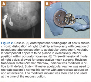
Preoperative radiographs showed a right uncemented THA with the femoral head dislocated toward the false acetabulum, retained hardware, and an old ununited trochanteric fragment. Both the femoral and acetabular components appeared well-fixed, though the acetabular component was positioned inferior, toward the obturator foramen.
Preoperative CT with metal artifact subtraction was used to create a 3-D model of the residual bony pelvis. The model was made by an implant manufacturer (Zimmer, Warsaw, Indiana). The shape of the superior defect was amenable to reconstruction using a modified revision trabecular metal socket. The pelvic model was reamed to accept a conventional hemispherical socket. The defect was reamed to accept a modified revision trabecular metal socket. The real implant was fashioned before surgery and was sterilized to avoid the need for intraoperative modification. Use of the preoperative model significantly reduced the time that would have been needed to modify the implant during actual surgery.
The patient’s right THA was revised. At time of surgery, the modified revision trabecular metal acetabular component was noted to seat appropriately in the superior defect. The true acetabulum was reestablished, and a hemispherical socket was placed with multiple screws. The 2 components were then unitized using cement in the same manner as would be done with an off-the-shelf augment.
Case 3
A 57-year-old man presented with a 10-year history of right knee pain. About 30 years before presentation at our clinic, he was treated for an open right tibia fracture sustained in a motorcycle accident. He had been treated nonsurgically, with injections, but they failed to provide sustained relief.
Preoperative radiographs showed severe advanced DJD in conjunction with an extra-articular posttraumatic varus tibial shaft deformity (Figure 3). An implant manufacturer (Zimmer) used a CT scan to create a model of the deformity. The resultant center of rotation angle was calculated using preoperative images and conventional techniques for deformity correction, and a lateral closing-wedge osteotomy was performed on the CT-based model. The initial attempt at deformity correction was slightly excessive, and the amount of resected bone slightly thicker than the calculated wedge, resulting in a valgus deformity. This error was noted, and the decision was made to recut a new model with a slight amount of residual varus that could be corrected during the final knee arthroplasty procedure.
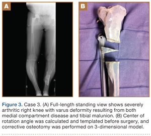
Corrective osteotomy was performed with a lateral plate. Six months later, the patient had no residual pain, and CT confirmed union at the osteotomy site and a slight amount of residual varus. The patient then underwent routine total knee arthroplasty (TKA) using an abbreviated keel to avoid the need for removal of the previously placed hardware. The varus deformity was completely corrected.
Case 4
A 73-year-old man had a history of shoulder pain dating back to his childhood. Despite treatment with nonsteroidal anti-inflammatory drugs, physical therapy, and injections, his debilitating pain persisted. Physical examination revealed limited ROM and an intact rotator cuff.
Plain radiographs showed severe DJD of the glenohumeral joint (Figure 4). Severe erosions of the glenoid were noted, prompting further workup with CT, which showed significant bone loss, particularly along the posterior margin of the glenoid. We used our 3-D printer to create a model of the scapula from CT images. The model was then reamed in the usual fashion to accept a 3-pegged glenoid component. On placement of a trial implant, a large deficiency was seen posteriorly. We thought the size and location of the defect made it amenable to grafting using the patient’s humeral head.
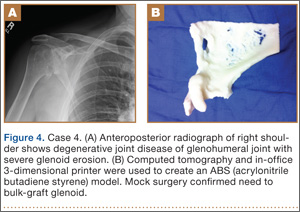
The patient elected to undergo right total shoulder arthroplasty. During the procedure, the glenoid defect was found to be identical to what was encountered with the model before surgery. A portion of the patient’s humeral head was then fashioned to fit the defect, and was secured with three 2.7-mm screws, after provisional fixation using 2.0-mm Kirschner wires. The screws were countersunk, and the graft was contoured by hand to match the previous reaming. A 3-pegged 52-mm glenoid component was then cemented into position with excellent stability.
Case 5
A 64-year-old man presented to our clinic with left hip pain 40 years after THA. The original procedure was performed for resolved proximal femoral osteomyelitis. Plain radiographs showed a loose cemented McKee-Farrar hip arthroplasty (Figure 5). Because of the elevated position of the acetabular component relative to the native hip center, CT was used to determine the amount of femoral bone loss.
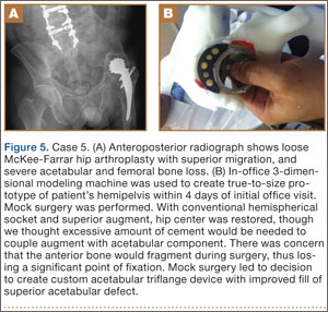
We used our 3-D printer to create a model and tried to recreate the native hip center with conventional off-the-shelf implants. A 50-mm hemispherical socket trial was placed in the appropriate location, along with a trabecular metal augment trial to provide extended coverage over the superolateral portion of the socket. Noted between the socket and the augment was a large gap; a substantial amount of cement would have been needed to unitize the construct. We thought a custom acetabular component would avoid the need for cement. In addition, given the patient’s small stature, the conventional acetabular component would allow a head only 32 mm in diameter. With a custom implant, the head could be enlarged to 36 mm, providing improved ROM and stability.
The patient underwent revision left hip arthroplasty using a custom acetabular component. A 3-D model available at time of surgery was used to aid implant placement.
Case 6
A 23-year-old man with multiple hereditary exostoses presented to our clinic with a painful mass in the left calf. Plain radiographs showed extensive osteochondromatosis involving the left proximal tibiofibular joint (Figure 6). The exostosis extended posteromedially, displacing the arterial trifurcation. MRI showed a small cartilage cap without evidence of malignant transformation.
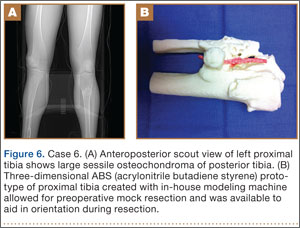
CT angiogram allowed the vasculature to be modeled along with the deformity. A 3-D model was fabricated. The model included the entire proximal tibiofibular joint, as well as the anterior tibial, peroneal, and posterior tibial arteries. Cautious intralesional resection was recommended because of the proximity to all 3 vessels.
The patient underwent tumor resection through a longitudinal posterior approach. The interval between the medial and lateral heads of the gastrocnemius muscles was developed to expose the underlying soleus muscle. The soleus was split longitudinally from its hiatus to the inferior portion of the exostosis. This allowed for identification of the trifurcation and the tibial nerve, which were protected. Osteotomes were used to resect the mass at its base, the edges were carefully trimmed, and bone wax was placed over the defect. Anterior and lateral to this mass was another large mass (under the soleus muscle), which was also transected using an osteotome. The gastrocnemius and soleus muscles were then reflected off the fibula in order to remove 2 other exostoses, beneath the neck and head of the fibula.
Case 7
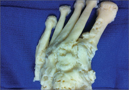
A 71-year-old man with a history of idiopathic lymphedema and peripheral neuropathy presented to our clinic with a left cavovarus foot deformity and a history of recurrent neuropathic foot ulcers (Figure 7). Physical examination revealed a callus over the lateral aspect of the base of the fifth metatarsal. Preoperative radiograph showed evidence of prior triple arthrodesis with a cavovarus foot deformity. CT scan was used to create a 3-D model of the foot. The model was then used to identify an appropriate location for lateral midtarsal and calcaneal closing-wedge osteotomies.
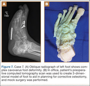
The patient underwent midfoot and hindfoot surgical correction. At surgery, the lateral closing-wedge osteotomies were performed according to the preoperative model. Radiographs 1 year after surgery showed correction of the forefoot varus.
Discussion
Three-dimensional printing for medical applications of anatomical modeling is not a new concept.1,3,4 Its use has been reported for a variety of applications in orthopedic surgery, including the printing of porous and metallic surfaces5 and bone-tissue engineering.6-9 Rapid prototyping for medical application was first reported in 1990 when a CT-based model was used to create a cranial bone.10 Reports of using the technique are becoming more widespread, particularly in the dental and maxillofacial literature, which includes reports on a variety of applications, including patient-specific drill guides, splints, and implants.11-14 The ability to perform mock surgery in advance of an actual procedure provides an invaluable opportunity to anticipate potential intraoperative problems, reduce operative time, and improve the accuracy of reconstruction.
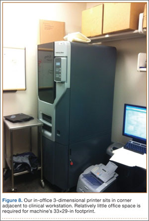
Office-based rapid prototyping that uses an in-house 3-D printer is a novel application of this technology. It allows for creation of a patient-specific model for preoperative planning purposes. We are unaware of any other reports demonstrating the breadth and utility of office-based rapid prototyping in orthopedic surgery. For general reference, a printer similar to ours requires an initial investment of $52,000 to $56,000. This cost generally covers the printer, printer base cabinet, installation, training, and printer software (different from the 3-D modeling software), plus a 1-year warranty. A service agreement costs about $4000 annually. Printer and model supply expenses depend on the material used for the model (eg, ABS [acrylonitrile butadiene styrene]) and on the size and complexity of the 3-D models created. Average time to generate an appropriately formatted 3-D printing file is about 1 hour, though times can vary largely, according to amount of metal artifact subtraction necessary and the experience of the software user. For the rare, extremely complex deformities that require a significant amount of metal artifact subtraction, file preparation times can exceed 3 or 4 hours. We think these preparation times will decrease as communication between radiology file export format and modeling software ultimately allows for metal artifact subtraction images to function within the modeling software environment. Once an appropriately formatted file has been created, typical printing times vary according to the size of the to-be-modeled bone. For a hemipelvis, printing time is 30 to 40 hours; printing that is started on a Friday afternoon will be complete by Monday morning.
There are few reports of rapid prototyping in orthopedic surgery. In 2003, Minns and colleagues15 used a 3-D model in the planning of a tibial resection for TKA. They found the model to be accurate at time of surgery, resulting in appropriate tibial coverage by a conventional meniscal-bearing implant. Munjal and colleagues16 reported on 10 complex failed hip arthroplasty cases in which patients had revision surgery after preoperative planning using 3-D modeling techniques. The authors found that, in 8 of the 10 cases, conventional classification systems of bone loss were inaccurate in comparison with the prototype. Four cases required reconstruction with a custom triflange when conventional implants were not deemed reasonable based on the pelvic model. Tam and colleagues17 reported using a 3-D prototype as an aid in surgical planning for resection of a scapular osteochondroma in a 6-year-old patient. They found the rapid prototype to be useful at time of resection—similar to what we found with 1 patient (case 6). Adding contrast media to our patient’s scan allowed for 3-D visualization of the lesion and the encased vasculature. Fu and colleagues18 reported using a patient-specific drill template to insert anterior transpedicular screws. They constructed 24 prototypes of a formalin-preserved cervical vertebra to create a patient-specific biocompatible drill template for use in correcting multilevel cervical instability. They found the technique to be highly reproducible and accurate. Zein and colleagues19 used a rapid prototype of 3 consecutive human livers to preoperatively identify the vascular and biliary tract anatomy. They reported a high degree of accuracy—mean dimensional errors of less than 4 mm for the entire model and 1.3 mm for the vascular diameter.
The models created by implant manufacturers in this series were used to perform “mock” surgery before the actual procedures. Working with these models prompted us to buy our own 3-D printer. The learning curve can be steep, but commercially available 3-D printers allow for prompt in-office production of high-quality realistic prototypes at relatively low per-case cost (Figure 8). Three-dimensional modeling allows surgeons to assess the accuracy of their original surgical plans and, if necessary, correct them before surgery. Although computer-aided design models are useful, the ability to “perform surgery preoperatively” adds another element to surgeons’ understanding of the potential issues that may arise. Also, an in-office printer can help improve surgeons’ understanding and control over the process by which images are translated from radiographic file to 3-D model. Disadvantages of an in-office system include start-up and maintenance costs, office space requirements, and a significant learning curve for software and hardware applications. In addition, creation of 3-D models requires close interaction with radiologists who can provide appropriately formatted DICOM images, as metal artifact subtraction can be challenging. We think that, as image formatting and software capabilities are continually refined, this technology will become an invaluable part of multiple subspecialties across orthopedic surgery, with potentially infinite clinical, educational, and research applications.
1. McGurk M, Amis AA, Potamianos P, Goodger NM. Rapid prototyping techniques for anatomical modelling in medicine. Ann R Coll Surg Engl. 1997;79(3):169-174.
2. Webb PA. A review of rapid prototyping (RP) techniques in the medical and biomedical sector. J Med Eng Technol. 2000;24(4):149-153.
3. Esses SJ, Berman P, Bloom AI, Sosna J. Clinical applications of physical 3D models derived from MDCT data and created by rapid prototyping. AJR Am J Roentgenol. 2011;196(6):W683-W688.
4. Torres K, Staśkiewicz G, Śnieżyński M, Drop A, Maciejewski R. Application of rapid prototyping techniques for modelling of anatomical structures in medical training and education. Folia Morphol. 2011;70(1):1-4.
5. Melican MC, Zimmerman MC, Dhillon MS, Ponnambalam AR, Curodeau A, Parsons JR. Three-dimensional printing and porous metallic surfaces: a new orthopedic application. J Biomed Mater Res. 2001;55(2):194-202.
6. Butscher A, Bohner M, Hofmann S, Gauckler L, Müller R. Structural and material approaches to bone tissue engineering in powder-based three-dimensional printing. Acta Biomater. 2011;7(3):907-920.
7. Ciocca L, De Crescenzio F, Fantini M, Scotti R. CAD/CAM and rapid prototyped scaffold construction for bone regenerative medicine and surgical transfer of virtual planning: a pilot study. Comput Med Imaging Graph. 2009;33(1):58-62.
8. Leukers B, Gülkan H, Irsen SH, et al. Hydroxyapatite scaffolds for bone tissue engineering made by 3D printing. J Mater Sci Mater Med. 2005;16(12):1121-1124.
9. Seitz H, Rieder W, Irsen S, Leukers B, Tille C. Three-dimensional printing of porous ceramic scaffolds for bone tissue engineering. J Biomed Mater Res B Appl Biomater. 2005;74(2):782-788.
10. Mankovich NJ, Cheeseman AM, Stoker NG. The display of three-dimensional anatomy with stereolithographic models. J Digit Imaging. 1990;3(3):200-203.
11. Flügge TV, Nelson K, Schmelzeisen R, Metzger MC. Three-dimensional plotting and printing of an implant drilling guide: simplifying guided implant surgery. J Oral Maxillofac Surg. 2013;71(8):1340-1346.
12. Goiato MC, Santos MR, Pesqueira AA, Moreno A, dos Santos DM, Haddad MF. Prototyping for surgical and prosthetic treatment. J Craniofac Surg. 2011;22(3):914-917.
13. Metzger MC, Hohlweg-Majert B, Schwarz U, Teschner M, Hammer B, Schmelzeisen R. Manufacturing splints for orthognathic surgery using a three-dimensional printer. Oral Surg Oral Med Oral Pathol Oral Radiol Endod. 2008;105(2):e1-e7.
14. Robiony M, Salvo I, Costa F, et al. Virtual reality surgical planning for maxillofacial distraction osteogenesis: the role of reverse engineering rapid prototyping and cooperative work. J Oral Maxillofac Surg. 2007;65(6):1198-1208.
15. Minns RJ, Bibb R, Banks R, Sutton RA. The use of a reconstructed three-dimensional solid model from CT to aid the surgical management of a total knee arthroplasty: a case study. Med Eng Phys. 2003;25(6):523-526.
16. Munjal S, Leopold SS, Kornreich D, Shott S, Finn HA. CT-generated 3-dimensional models for complex acetabular reconstruction. J Arthroplasty. 2000;15(5):644-653.
17. Tam MD, Laycock SD, Bell D, Chojnowski A. 3-D printout of a DICOM file to aid surgical planning in a 6 year old patient with a large scapular osteochondroma complicating congenital diaphyseal aclasia. J Radiol Case Rep. 2012;6(1):31-37.
18. Fu M, Lin L, Kong X, et al. Construction and accuracy assessment of patient-specific biocompatible drill template for cervical anterior transpedicular screw (ATPS) insertion: an in vitro study. PLoS One. 2013;8(1):e53580.
19. Zein NN, Hanouneh IA, Bishop PD, et al. Three-dimensional print of a liver for preoperative planning in living donor liver transplantation. Liver Transpl. 2013;19(12):1304-1310.
Three-dimensional (3-D) printing is a rapidly evolving technology with both medical and nonmedical applications.1,2 Rapid prototyping involves creating a physical model of human tissue from a 3-D computer-generated rendering.3 The method relies on export of Digital Imaging and Communications in Medicine (DICOM)–based computed tomography (CT) or magnetic resonance imaging (MRI) data into standard triangular language (STL) format. Reducing CT or MRI slice thickness increases resolution of the final model.2 Five types of rapid prototyping exist: STL, selective laser sintering, fused deposition modeling, multijet modeling, and 3-D printing.
Most implant manufacturers can produce a 3-D model based on surgeon-provided DICOM images. The ability to produce anatomical models in an office-based setting is a more recent development. Three-dimensional modeling may allow for more accurate and extensive preoperative planning than radiographic examination alone does, and may even allow surgeons to perform procedures as part of preoperative preparation. This can allow for early recognition of unanticipated intraoperative problems or of the need for special techniques and implants that would not have been otherwise available, all of which may ultimately reduce operative time.
The breadth of applications for office-based 3-D prototyping is not well described in the orthopedic surgery literature. In this article, we describe 7 cases of complex orthopedic disorders that were surgically treated after preoperative planning in which use of a 3-D printer allowed for “mock” surgery before the actual procedures. In 3 of the cases, the models were made by the implant manufacturers. Working with these models prompted us to buy a 3-D printer (Fortus 250; Stratasys, Eden Prairie, Minnesota) for in-office use. In the other 4 cases, we used this printer to create our own models. As indicated in the manufacturer’s literature, the printer uses fused deposition modeling, which builds a model layer by layer by heating thermoplastic material to a semi-liquid state and extruding it according to computer-controlled pathways.
We present preoperative images, preoperative 3-D modeling, and intraoperative and postoperative images along with brief case descriptions (Table). The patients provided written informed consent for print and electronic publication of these case reports.
Case Reports
Case 1
A 28-year-old woman with a history of spondyloepiphyseal dysplasia presented to our clinic with bilateral hip pain. About 8 years earlier, she had undergone bilateral proximal and distal femoral osteotomies. Her function had initially improved, but over the 2 to 3 years before presentation she began having more pain and stiffness with activity. At time of initial evaluation, she was able to walk only 1 to 2 blocks and had difficulty getting in and out of a car and up out of a seated position.
On physical examination, the patient was 3 feet 10 inches tall and weighed 77 pounds. She ambulated with decreased stance phase on both lower extremities and had developed a significant amount of increased forward pelvic inclination and increased lumbar lordosis. Both hips and thighs had multiple healed scars from prior surgeries and pin tracts. Range of motion (ROM) on both sides was restricted to 85° of flexion, 10° of internal rotation, 15° of external rotation, and 15° of abduction.
Plain radiographs showed advanced degenerative joint disease (DJD) of both hips with dysplastic acetabuli and evidence of healed osteotomies (Figure 1). Femoral deformities, noted bilaterally, consisted of marked valgus proximally and varus distally. Preoperative CT was used to create a 3-D model of the pelvis and femur. The model was created by the same implant manufacturer that produced the final components (Depuy, Warsaw, Indiana). Corrective femoral osteotomy was performed on the model to allow for design and use of a custom implant, while the modeled pelvis confirmed the ability to reproduce the normal hip center with a 44-mm conventional hemispherical socket.
After surgery, the patient was able to ambulate without a limp and return to work. Her hip ROM was pain-free passively and actively with flexion to 100°, internal rotation to 35°, external rotation to 20°, and abduction to 30°.
Case 2
A 48-year-old woman with a history of Crowe IV hip dysplasia presented to our clinic with a chronically dislocated right total hip arthroplasty (THA) (Figure 2). Her initial THA was revised 1 year later because of acetabular component failure. Two years later, she was diagnosed with a deep periprosthetic infection, which was ultimately treated with 2-stage reimplantation. She subsequently dislocated and underwent re-revision of the S-ROM body and stem (DePuy Synthes, Warsaw, Indiana). At a visit after that revision, she was noted to be chronically dislocated, and was sent to our clinic for further management.
Preoperative radiographs showed a right uncemented THA with the femoral head dislocated toward the false acetabulum, retained hardware, and an old ununited trochanteric fragment. Both the femoral and acetabular components appeared well-fixed, though the acetabular component was positioned inferior, toward the obturator foramen.
Preoperative CT with metal artifact subtraction was used to create a 3-D model of the residual bony pelvis. The model was made by an implant manufacturer (Zimmer, Warsaw, Indiana). The shape of the superior defect was amenable to reconstruction using a modified revision trabecular metal socket. The pelvic model was reamed to accept a conventional hemispherical socket. The defect was reamed to accept a modified revision trabecular metal socket. The real implant was fashioned before surgery and was sterilized to avoid the need for intraoperative modification. Use of the preoperative model significantly reduced the time that would have been needed to modify the implant during actual surgery.
The patient’s right THA was revised. At time of surgery, the modified revision trabecular metal acetabular component was noted to seat appropriately in the superior defect. The true acetabulum was reestablished, and a hemispherical socket was placed with multiple screws. The 2 components were then unitized using cement in the same manner as would be done with an off-the-shelf augment.
Case 3
A 57-year-old man presented with a 10-year history of right knee pain. About 30 years before presentation at our clinic, he was treated for an open right tibia fracture sustained in a motorcycle accident. He had been treated nonsurgically, with injections, but they failed to provide sustained relief.
Preoperative radiographs showed severe advanced DJD in conjunction with an extra-articular posttraumatic varus tibial shaft deformity (Figure 3). An implant manufacturer (Zimmer) used a CT scan to create a model of the deformity. The resultant center of rotation angle was calculated using preoperative images and conventional techniques for deformity correction, and a lateral closing-wedge osteotomy was performed on the CT-based model. The initial attempt at deformity correction was slightly excessive, and the amount of resected bone slightly thicker than the calculated wedge, resulting in a valgus deformity. This error was noted, and the decision was made to recut a new model with a slight amount of residual varus that could be corrected during the final knee arthroplasty procedure.
Corrective osteotomy was performed with a lateral plate. Six months later, the patient had no residual pain, and CT confirmed union at the osteotomy site and a slight amount of residual varus. The patient then underwent routine total knee arthroplasty (TKA) using an abbreviated keel to avoid the need for removal of the previously placed hardware. The varus deformity was completely corrected.
Case 4
A 73-year-old man had a history of shoulder pain dating back to his childhood. Despite treatment with nonsteroidal anti-inflammatory drugs, physical therapy, and injections, his debilitating pain persisted. Physical examination revealed limited ROM and an intact rotator cuff.
Plain radiographs showed severe DJD of the glenohumeral joint (Figure 4). Severe erosions of the glenoid were noted, prompting further workup with CT, which showed significant bone loss, particularly along the posterior margin of the glenoid. We used our 3-D printer to create a model of the scapula from CT images. The model was then reamed in the usual fashion to accept a 3-pegged glenoid component. On placement of a trial implant, a large deficiency was seen posteriorly. We thought the size and location of the defect made it amenable to grafting using the patient’s humeral head.
The patient elected to undergo right total shoulder arthroplasty. During the procedure, the glenoid defect was found to be identical to what was encountered with the model before surgery. A portion of the patient’s humeral head was then fashioned to fit the defect, and was secured with three 2.7-mm screws, after provisional fixation using 2.0-mm Kirschner wires. The screws were countersunk, and the graft was contoured by hand to match the previous reaming. A 3-pegged 52-mm glenoid component was then cemented into position with excellent stability.
Case 5
A 64-year-old man presented to our clinic with left hip pain 40 years after THA. The original procedure was performed for resolved proximal femoral osteomyelitis. Plain radiographs showed a loose cemented McKee-Farrar hip arthroplasty (Figure 5). Because of the elevated position of the acetabular component relative to the native hip center, CT was used to determine the amount of femoral bone loss.
We used our 3-D printer to create a model and tried to recreate the native hip center with conventional off-the-shelf implants. A 50-mm hemispherical socket trial was placed in the appropriate location, along with a trabecular metal augment trial to provide extended coverage over the superolateral portion of the socket. Noted between the socket and the augment was a large gap; a substantial amount of cement would have been needed to unitize the construct. We thought a custom acetabular component would avoid the need for cement. In addition, given the patient’s small stature, the conventional acetabular component would allow a head only 32 mm in diameter. With a custom implant, the head could be enlarged to 36 mm, providing improved ROM and stability.
The patient underwent revision left hip arthroplasty using a custom acetabular component. A 3-D model available at time of surgery was used to aid implant placement.
Case 6
A 23-year-old man with multiple hereditary exostoses presented to our clinic with a painful mass in the left calf. Plain radiographs showed extensive osteochondromatosis involving the left proximal tibiofibular joint (Figure 6). The exostosis extended posteromedially, displacing the arterial trifurcation. MRI showed a small cartilage cap without evidence of malignant transformation.
CT angiogram allowed the vasculature to be modeled along with the deformity. A 3-D model was fabricated. The model included the entire proximal tibiofibular joint, as well as the anterior tibial, peroneal, and posterior tibial arteries. Cautious intralesional resection was recommended because of the proximity to all 3 vessels.
The patient underwent tumor resection through a longitudinal posterior approach. The interval between the medial and lateral heads of the gastrocnemius muscles was developed to expose the underlying soleus muscle. The soleus was split longitudinally from its hiatus to the inferior portion of the exostosis. This allowed for identification of the trifurcation and the tibial nerve, which were protected. Osteotomes were used to resect the mass at its base, the edges were carefully trimmed, and bone wax was placed over the defect. Anterior and lateral to this mass was another large mass (under the soleus muscle), which was also transected using an osteotome. The gastrocnemius and soleus muscles were then reflected off the fibula in order to remove 2 other exostoses, beneath the neck and head of the fibula.
Case 7
A 71-year-old man with a history of idiopathic lymphedema and peripheral neuropathy presented to our clinic with a left cavovarus foot deformity and a history of recurrent neuropathic foot ulcers (Figure 7). Physical examination revealed a callus over the lateral aspect of the base of the fifth metatarsal. Preoperative radiograph showed evidence of prior triple arthrodesis with a cavovarus foot deformity. CT scan was used to create a 3-D model of the foot. The model was then used to identify an appropriate location for lateral midtarsal and calcaneal closing-wedge osteotomies.
The patient underwent midfoot and hindfoot surgical correction. At surgery, the lateral closing-wedge osteotomies were performed according to the preoperative model. Radiographs 1 year after surgery showed correction of the forefoot varus.
Discussion
Three-dimensional printing for medical applications of anatomical modeling is not a new concept.1,3,4 Its use has been reported for a variety of applications in orthopedic surgery, including the printing of porous and metallic surfaces5 and bone-tissue engineering.6-9 Rapid prototyping for medical application was first reported in 1990 when a CT-based model was used to create a cranial bone.10 Reports of using the technique are becoming more widespread, particularly in the dental and maxillofacial literature, which includes reports on a variety of applications, including patient-specific drill guides, splints, and implants.11-14 The ability to perform mock surgery in advance of an actual procedure provides an invaluable opportunity to anticipate potential intraoperative problems, reduce operative time, and improve the accuracy of reconstruction.
Office-based rapid prototyping that uses an in-house 3-D printer is a novel application of this technology. It allows for creation of a patient-specific model for preoperative planning purposes. We are unaware of any other reports demonstrating the breadth and utility of office-based rapid prototyping in orthopedic surgery. For general reference, a printer similar to ours requires an initial investment of $52,000 to $56,000. This cost generally covers the printer, printer base cabinet, installation, training, and printer software (different from the 3-D modeling software), plus a 1-year warranty. A service agreement costs about $4000 annually. Printer and model supply expenses depend on the material used for the model (eg, ABS [acrylonitrile butadiene styrene]) and on the size and complexity of the 3-D models created. Average time to generate an appropriately formatted 3-D printing file is about 1 hour, though times can vary largely, according to amount of metal artifact subtraction necessary and the experience of the software user. For the rare, extremely complex deformities that require a significant amount of metal artifact subtraction, file preparation times can exceed 3 or 4 hours. We think these preparation times will decrease as communication between radiology file export format and modeling software ultimately allows for metal artifact subtraction images to function within the modeling software environment. Once an appropriately formatted file has been created, typical printing times vary according to the size of the to-be-modeled bone. For a hemipelvis, printing time is 30 to 40 hours; printing that is started on a Friday afternoon will be complete by Monday morning.
There are few reports of rapid prototyping in orthopedic surgery. In 2003, Minns and colleagues15 used a 3-D model in the planning of a tibial resection for TKA. They found the model to be accurate at time of surgery, resulting in appropriate tibial coverage by a conventional meniscal-bearing implant. Munjal and colleagues16 reported on 10 complex failed hip arthroplasty cases in which patients had revision surgery after preoperative planning using 3-D modeling techniques. The authors found that, in 8 of the 10 cases, conventional classification systems of bone loss were inaccurate in comparison with the prototype. Four cases required reconstruction with a custom triflange when conventional implants were not deemed reasonable based on the pelvic model. Tam and colleagues17 reported using a 3-D prototype as an aid in surgical planning for resection of a scapular osteochondroma in a 6-year-old patient. They found the rapid prototype to be useful at time of resection—similar to what we found with 1 patient (case 6). Adding contrast media to our patient’s scan allowed for 3-D visualization of the lesion and the encased vasculature. Fu and colleagues18 reported using a patient-specific drill template to insert anterior transpedicular screws. They constructed 24 prototypes of a formalin-preserved cervical vertebra to create a patient-specific biocompatible drill template for use in correcting multilevel cervical instability. They found the technique to be highly reproducible and accurate. Zein and colleagues19 used a rapid prototype of 3 consecutive human livers to preoperatively identify the vascular and biliary tract anatomy. They reported a high degree of accuracy—mean dimensional errors of less than 4 mm for the entire model and 1.3 mm for the vascular diameter.
The models created by implant manufacturers in this series were used to perform “mock” surgery before the actual procedures. Working with these models prompted us to buy our own 3-D printer. The learning curve can be steep, but commercially available 3-D printers allow for prompt in-office production of high-quality realistic prototypes at relatively low per-case cost (Figure 8). Three-dimensional modeling allows surgeons to assess the accuracy of their original surgical plans and, if necessary, correct them before surgery. Although computer-aided design models are useful, the ability to “perform surgery preoperatively” adds another element to surgeons’ understanding of the potential issues that may arise. Also, an in-office printer can help improve surgeons’ understanding and control over the process by which images are translated from radiographic file to 3-D model. Disadvantages of an in-office system include start-up and maintenance costs, office space requirements, and a significant learning curve for software and hardware applications. In addition, creation of 3-D models requires close interaction with radiologists who can provide appropriately formatted DICOM images, as metal artifact subtraction can be challenging. We think that, as image formatting and software capabilities are continually refined, this technology will become an invaluable part of multiple subspecialties across orthopedic surgery, with potentially infinite clinical, educational, and research applications.
1. McGurk M, Amis AA, Potamianos P, Goodger NM. Rapid prototyping techniques for anatomical modelling in medicine. Ann R Coll Surg Engl. 1997;79(3):169-174.
2. Webb PA. A review of rapid prototyping (RP) techniques in the medical and biomedical sector. J Med Eng Technol. 2000;24(4):149-153.
3. Esses SJ, Berman P, Bloom AI, Sosna J. Clinical applications of physical 3D models derived from MDCT data and created by rapid prototyping. AJR Am J Roentgenol. 2011;196(6):W683-W688.
4. Torres K, Staśkiewicz G, Śnieżyński M, Drop A, Maciejewski R. Application of rapid prototyping techniques for modelling of anatomical structures in medical training and education. Folia Morphol. 2011;70(1):1-4.
5. Melican MC, Zimmerman MC, Dhillon MS, Ponnambalam AR, Curodeau A, Parsons JR. Three-dimensional printing and porous metallic surfaces: a new orthopedic application. J Biomed Mater Res. 2001;55(2):194-202.
6. Butscher A, Bohner M, Hofmann S, Gauckler L, Müller R. Structural and material approaches to bone tissue engineering in powder-based three-dimensional printing. Acta Biomater. 2011;7(3):907-920.
7. Ciocca L, De Crescenzio F, Fantini M, Scotti R. CAD/CAM and rapid prototyped scaffold construction for bone regenerative medicine and surgical transfer of virtual planning: a pilot study. Comput Med Imaging Graph. 2009;33(1):58-62.
8. Leukers B, Gülkan H, Irsen SH, et al. Hydroxyapatite scaffolds for bone tissue engineering made by 3D printing. J Mater Sci Mater Med. 2005;16(12):1121-1124.
9. Seitz H, Rieder W, Irsen S, Leukers B, Tille C. Three-dimensional printing of porous ceramic scaffolds for bone tissue engineering. J Biomed Mater Res B Appl Biomater. 2005;74(2):782-788.
10. Mankovich NJ, Cheeseman AM, Stoker NG. The display of three-dimensional anatomy with stereolithographic models. J Digit Imaging. 1990;3(3):200-203.
11. Flügge TV, Nelson K, Schmelzeisen R, Metzger MC. Three-dimensional plotting and printing of an implant drilling guide: simplifying guided implant surgery. J Oral Maxillofac Surg. 2013;71(8):1340-1346.
12. Goiato MC, Santos MR, Pesqueira AA, Moreno A, dos Santos DM, Haddad MF. Prototyping for surgical and prosthetic treatment. J Craniofac Surg. 2011;22(3):914-917.
13. Metzger MC, Hohlweg-Majert B, Schwarz U, Teschner M, Hammer B, Schmelzeisen R. Manufacturing splints for orthognathic surgery using a three-dimensional printer. Oral Surg Oral Med Oral Pathol Oral Radiol Endod. 2008;105(2):e1-e7.
14. Robiony M, Salvo I, Costa F, et al. Virtual reality surgical planning for maxillofacial distraction osteogenesis: the role of reverse engineering rapid prototyping and cooperative work. J Oral Maxillofac Surg. 2007;65(6):1198-1208.
15. Minns RJ, Bibb R, Banks R, Sutton RA. The use of a reconstructed three-dimensional solid model from CT to aid the surgical management of a total knee arthroplasty: a case study. Med Eng Phys. 2003;25(6):523-526.
16. Munjal S, Leopold SS, Kornreich D, Shott S, Finn HA. CT-generated 3-dimensional models for complex acetabular reconstruction. J Arthroplasty. 2000;15(5):644-653.
17. Tam MD, Laycock SD, Bell D, Chojnowski A. 3-D printout of a DICOM file to aid surgical planning in a 6 year old patient with a large scapular osteochondroma complicating congenital diaphyseal aclasia. J Radiol Case Rep. 2012;6(1):31-37.
18. Fu M, Lin L, Kong X, et al. Construction and accuracy assessment of patient-specific biocompatible drill template for cervical anterior transpedicular screw (ATPS) insertion: an in vitro study. PLoS One. 2013;8(1):e53580.
19. Zein NN, Hanouneh IA, Bishop PD, et al. Three-dimensional print of a liver for preoperative planning in living donor liver transplantation. Liver Transpl. 2013;19(12):1304-1310.