Posterolateral rotatory instability (PLRI) of the elbow is well recognized1 and is the most common type of chronic elbow instability. PLRI is often an end result of traumatic elbow dislocation.2 The “essential lesion” in patients with PLRI of the elbow is injury to the lateral ulnar collateral ligament (LUCL).1 However, more recent research has emphasized the importance of other ligaments in the lateral ligament complex (radial collateral and annular ligaments) in preventing PLRI.3-5 Nevertheless, when conservative treatment fails, the most commonly used surgical treatment involves LUCL reconstruction.1,6-11
Numerous techniques for LUCL reconstruction have been described.1,7-9,11-13 The chosen technique ideally restores normal anatomy. Therefore, the isometric point of origin at the lateral epicondyle and insertion at the supinator tubercle are important landmarks for creating tunnels that reproduce isometry, function, and normal anatomy. Most often, 2 tunnels are created in the ulna to secure the graft. It has been our experience that ulnar tunnel creation can affect the length of the bony bridge and the orientation of the graft.
We conducted a study to identify the precise proximal ulna tunnel location—anterior to posterior, with the distal tunnel at the supinator tubercle on the crest—that allows for the largest bony bridge and most geometrically favorable construct. We hypothesized that a most posteriorly placed proximal tunnel would increase bony bridge size and allow for a more isosceles graft configuration. An isosceles configuration with the humerus tunnel at the isometric location would allow for anterior and posterior bands of the same length with theoretically equal force distribution.
Methods
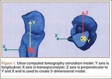
After obtaining institutional review board approval, we retrospectively reviewed the cases of 17 adults with elbow computed tomography (CT) scans for inclusion in this study. The scans were previously performed for diagnostic workup of several pathologies, including valgus instability, olecranon stress fracture, and valgus extension overload. The scan protocol involved 0.5-mm axial cuts with inclusion of the distal humerus through the proximal radius and ulna in the DICOM (Digital Imaging and Communications in Medicine) format. Exclusion criteria included poor CT quality, inadequate visualization of the entire supinator crest, and age under 18 years. Fifteen patients with adequate CT scans met the inclusion criteria. MIMICS (Materialise’s Interactive Medical Image Control System) software was used to convert scans into patient-specific 3-dimensional (3-D) computer models. (Use of this software to produce anatomically accurate models has been verified in shoulder14 and elbow15 models.) These models were uploaded into Magics rapid prototyping software (Materialise) and manipulated for simulated tunnel drilling by precise bone subtraction methods. This software was used to define an ulnar Cartesian coordinate system with anatomical landmarks as reference points in order to standardize the position of each model (Figure 1).16 The y-axis was defined by the longitudinal axis of the ulna, and the x-axis was the transepicondylar axis, defined as the perpendicular line connecting the y-axis with the supinator crest. The z-axis was then established as the line perpendicular to the x- and y-axes—yielding a 3-D coordinate system that allowed us to manipulate the models in standardized fashion, maintaining the exact positions of the ulna while making measurements.
Surgical simulations were performed in the rapid prototyping software by creating a cylinder and placing it at the desired location of each tunnel. Cylinder diameter was 4 mm, matching the diameter of the drill we use to create each tunnel in our practice. The cylinder was inserted into the bone, perpendicular to the surface of the ulna at the point of insertion, so the cylinder’s deepest point entered the medullary canal of the ulna. Using a Boolean operation in the rapid prototyping software, we subtracted cylinder from bone to create a tunnel (Figure 2).15
In a previous study,17 we determined that the radial head junction is reproducibly about 15 mm proximal to the distinct supinator tubercle, which may be absent or not readily appreciated in up to 50% of cases. Therefore, proximal ulnar tunnels were placed 0, 5, and 10 mm posterior to the supinator crest at the radial head junction. Distal tunnels were placed 15 mm anterior to the radial head junction on the supinator crest (Figure 2). The bony bridges created by these tunnels were measured, as was the distance between the distal tunnel and the supinator tubercle.
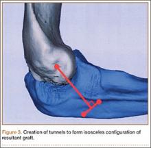
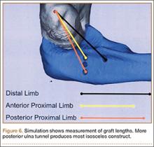
Ideal graft configuration was described as an isosceles triangle with ulna tunnels perpendicular to the humeral tunnel (Figure 3).11 Location of the humeral origin in the sagittal plane was determined by finding the isometric point of the lateral humerus using only bony landmarks. Similar techniques have been used to find the isometric point on the medial epicondyle for medial ulnar collateral ligament reconstruction.15,18 With a circle fit into the trochlear notch of the ulna, the isometric point can be determined by the center of the circle. This point was then superimposed on the humerus to identify the starting point (Figure 4). In our simulation, we measured the isosceles configuration by drawing a line between the proximal and distal tunnels, and then another line connecting the bisecting point of the first line with the isometric point on the humerus from which the graft would originate. The angle between the 2 lines was measured; if isosceles, the angle was 90° (Figure 5). Length of the more proximal limb of the graft and the more distal limb of the graft was determined by measuring the distance from the isometric point to the proximal and distal tunnels, respectively (Figure 6).


