Preoperative radiographs showed a right uncemented THA with the femoral head dislocated toward the false acetabulum, retained hardware, and an old ununited trochanteric fragment. Both the femoral and acetabular components appeared well-fixed, though the acetabular component was positioned inferior, toward the obturator foramen.
Preoperative CT with metal artifact subtraction was used to create a 3-D model of the residual bony pelvis. The model was made by an implant manufacturer (Zimmer, Warsaw, Indiana). The shape of the superior defect was amenable to reconstruction using a modified revision trabecular metal socket. The pelvic model was reamed to accept a conventional hemispherical socket. The defect was reamed to accept a modified revision trabecular metal socket. The real implant was fashioned before surgery and was sterilized to avoid the need for intraoperative modification. Use of the preoperative model significantly reduced the time that would have been needed to modify the implant during actual surgery.
The patient’s right THA was revised. At time of surgery, the modified revision trabecular metal acetabular component was noted to seat appropriately in the superior defect. The true acetabulum was reestablished, and a hemispherical socket was placed with multiple screws. The 2 components were then unitized using cement in the same manner as would be done with an off-the-shelf augment.
Case 3
A 57-year-old man presented with a 10-year history of right knee pain. About 30 years before presentation at our clinic, he was treated for an open right tibia fracture sustained in a motorcycle accident. He had been treated nonsurgically, with injections, but they failed to provide sustained relief.
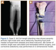
Preoperative radiographs showed severe advanced DJD in conjunction with an extra-articular posttraumatic varus tibial shaft deformity (Figure 3). An implant manufacturer (Zimmer) used a CT scan to create a model of the deformity. The resultant center of rotation angle was calculated using preoperative images and conventional techniques for deformity correction, and a lateral closing-wedge osteotomy was performed on the CT-based model. The initial attempt at deformity correction was slightly excessive, and the amount of resected bone slightly thicker than the calculated wedge, resulting in a valgus deformity. This error was noted, and the decision was made to recut a new model with a slight amount of residual varus that could be corrected during the final knee arthroplasty procedure.
Corrective osteotomy was performed with a lateral plate. Six months later, the patient had no residual pain, and CT confirmed union at the osteotomy site and a slight amount of residual varus. The patient then underwent routine total knee arthroplasty (TKA) using an abbreviated keel to avoid the need for removal of the previously placed hardware. The varus deformity was completely corrected.
Case 4
A 73-year-old man had a history of shoulder pain dating back to his childhood. Despite treatment with nonsteroidal anti-inflammatory drugs, physical therapy, and injections, his debilitating pain persisted. Physical examination revealed limited ROM and an intact rotator cuff.
Plain radiographs showed severe DJD of the glenohumeral joint (Figure 4). Severe erosions of the glenoid were noted, prompting further workup with CT, which showed significant bone loss, particularly along the posterior margin of the glenoid. We used our 3-D printer to create a model of the scapula from CT images. The model was then reamed in the usual fashion to accept a 3-pegged glenoid component. On placement of a trial implant, a large deficiency was seen posteriorly. We thought the size and location of the defect made it amenable to grafting using the patient’s humeral head.
The patient elected to undergo right total shoulder arthroplasty. During the procedure, the glenoid defect was found to be identical to what was encountered with the model before surgery. A portion of the patient’s humeral head was then fashioned to fit the defect, and was secured with three 2.7-mm screws, after provisional fixation using 2.0-mm Kirschner wires. The screws were countersunk, and the graft was contoured by hand to match the previous reaming. A 3-pegged 52-mm glenoid component was then cemented into position with excellent stability.
Case 5
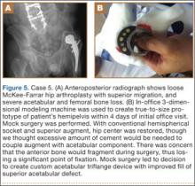
A 64-year-old man presented to our clinic with left hip pain 40 years after THA. The original procedure was performed for resolved proximal femoral osteomyelitis. Plain radiographs showed a loose cemented McKee-Farrar hip arthroplasty (Figure 5). Because of the elevated position of the acetabular component relative to the native hip center, CT was used to determine the amount of femoral bone loss.
We used our 3-D printer to create a model and tried to recreate the native hip center with conventional off-the-shelf implants. A 50-mm hemispherical socket trial was placed in the appropriate location, along with a trabecular metal augment trial to provide extended coverage over the superolateral portion of the socket. Noted between the socket and the augment was a large gap; a substantial amount of cement would have been needed to unitize the construct. We thought a custom acetabular component would avoid the need for cement. In addition, given the patient’s small stature, the conventional acetabular component would allow a head only 32 mm in diameter. With a custom implant, the head could be enlarged to 36 mm, providing improved ROM and stability.


