User login
Magnetic Resonance Imaging Evaluation of the Distal Biceps Tendon
ABSTRACT
Injuries to the distal biceps occur at the tendinous insertion at the radial tuberosity. Distal biceps injuries range from tendinosis to partial tears to non-retracted and retracted complete tears. Acute and chronic complete tears result from a tendinous avulsion at the radial tuberosity. Acute tears result from a strong force exerted on an eccentric biceps contraction, leading to tendon injury.
Distal biceps tendon injuries are uncommon (1.2 per 100,000 patients in one study).1 An underlying degenerative component is involved in all distal biceps tendon tears and tendinosis.2 Partial tears can be caused by the same mechanism or by no particular inciting event.3 Magnetic resonance imaging (MRI) is the optimal imaging modality for distal tendon tears because of its excellent specificity and sensitivity in the detection of complete tears.4,5 Imaging also accurately diagnoses and characterizes partial tears and tendinosis.5 On MRI, fast spin-echo intermediate-weighted and T2-weighted or short tau inversion recovery (STIR) sequences are normally obtained to assess tendon integrity. Along with standard axial and sagittal views, the FABS (flexed elbow, abducted shoulder, supinated forearm) view is an important tool in the diagnosis of distal biceps tendon tears.6 The FABS view is obtained with the patient prone with the shoulder abducted 180° (above the head), with the elbow flexed to 90°, and the forearm supinated. This position allows a longitudinal view of along the entire length of the distal tendon.
Complete distal biceps tears can usually be diagnosed by history and physical examinations. However, imaging can be helpful when intact brachialis function can compensate for a completely torn tendon. MRI is also useful in the setting of a complete tear to locate the torn tendon stump, and assess the degree of retraction for tendon retrieval7,8 and quality of the tendon stump for repair. For associated rupture of the lacertus, the degree of proximal tendon retraction can be significant (Figures 1A, 1B). 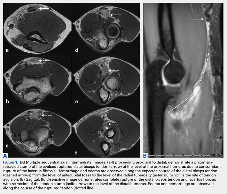
Continue to: Partial distal bicep tears...
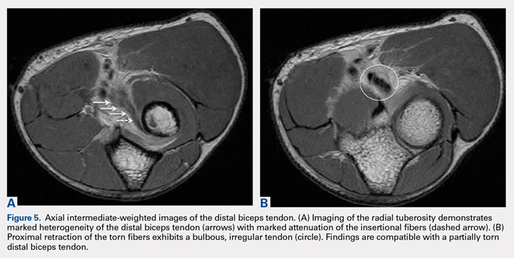
Partial distal bicep tears are characterized on MRI by focal or partial detachment of the tendon at the radial tuberosity with fluid filling the site of the tear. The degree of partial tearing can be assessed on MRI (Figures 5A, 5B).
MRI is useful in assessing the distal biceps tendon in the postoperative setting to evaluate the integrity of a repaired tendon. Cortical fixation button technique for repair creates minimal susceptibility artifacts on MRI. Postoperative MRI typically demonstrates a transverse hole drilled through the proximal radius at the site of the tuberosity with a cortical fixation button flush against the posterior radial cortex (Figures 8A-8D). 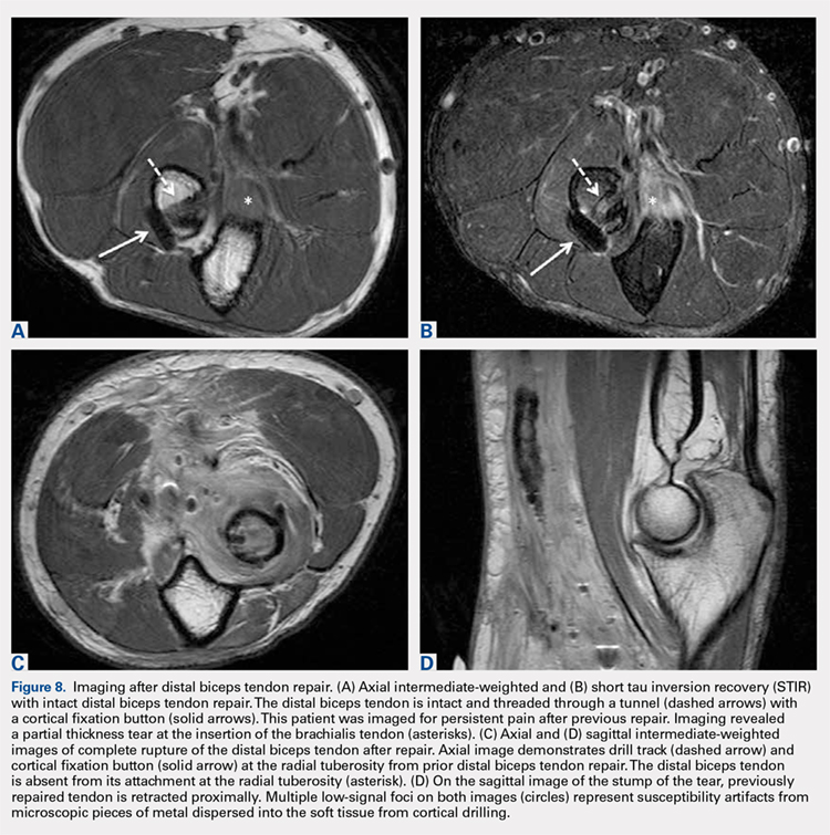
1. Safran M, Graham S. Distal biceps tendon ruptures. Clin Orthop Relat Res. 2002;404:275-283.
2. Kannus P, Józsa L. Histopathological changes preceding spontaneous rupture of a tendon. A controlled study of 891 patients. J Bone Joint Surg Am. 1991;73(10):1507-1525. doi:10.2106/00004623-199173100-00009.
3. Frazier M, Boardman M, Westland M, Imbriglia J. Surgical treatment of partial distal biceps tendon ruptures. J Hand Surg Am. 2010;35(7):1111-1114. doi:10.1016/j.jhsa.2010.04.024.
4. Festa A, Mulieri P, Newman J, Spitz D, Leslie B. Effectiveness of magnetic resonance imaging in detecting partial and complete distal biceps tendon rupture. J Hand Surg Am. 2010;35(1):77-83. doi:10.1016/j.jhsa.2009.08.016.
5. O'Driscoll S, Goncalves L, Dietz P. The hook test for distal biceps tendon avulsion. Am J Sports Med. 2007;35(11):1865-1869. doi:10.1177/0363546507305016.
6. Giuffrè B, Moss M. Optimal positioning for MRI of the distal biceps brachii tendon: flexed abducted supinated view. Am J Roentgenol. 2004;182(4):944-946. doi:10.2214/ajr.182.4.1820944.
7. Falchook F, Zlatkin M, Erbacher G, Moulton J, Bisset G. Murphy B. Rupture of the distal biceps tendon: evaluation with MR imaging. Radiology. 1994;190(3):659-663. doi:10.1148/radiology.190.3.8115606.
8. Fitzgerald S, Curry D, Erickson S, Quinn S, Friedman H. Distal biceps tendon injury: MR imaging diagnosis. Radiology. 1994;191(1):203-206. doi:10.1148/radiology.191.1.8134571.
9. Lehuec J, Zipoli B, Liquois F, Moinard M, Chauveaux D, Le Rebeller A. Distal rupture of the biceps tendon MRI evaluation and surgical repair. J Shoulder Elbow Surg. 1996;5(2):S49.
10. Dirim B, Brouha S, Pretterklieber M, et al. Terminal bifurcation of the biceps brachii muscle and tendon: anatomic considerations and clinical implications. Am J Roentgenol. 2008;191(6):W248-W255. doi:10.2214/AJR.08.1048.
11. Quach T, Jazayeri R, Sherman O, Rosen J. Distal biceps tendon injuries--current treatment options. Bull NYU Hosp Jt Dis. 2010;68(2):103-111.
ABSTRACT
Injuries to the distal biceps occur at the tendinous insertion at the radial tuberosity. Distal biceps injuries range from tendinosis to partial tears to non-retracted and retracted complete tears. Acute and chronic complete tears result from a tendinous avulsion at the radial tuberosity. Acute tears result from a strong force exerted on an eccentric biceps contraction, leading to tendon injury.
Distal biceps tendon injuries are uncommon (1.2 per 100,000 patients in one study).1 An underlying degenerative component is involved in all distal biceps tendon tears and tendinosis.2 Partial tears can be caused by the same mechanism or by no particular inciting event.3 Magnetic resonance imaging (MRI) is the optimal imaging modality for distal tendon tears because of its excellent specificity and sensitivity in the detection of complete tears.4,5 Imaging also accurately diagnoses and characterizes partial tears and tendinosis.5 On MRI, fast spin-echo intermediate-weighted and T2-weighted or short tau inversion recovery (STIR) sequences are normally obtained to assess tendon integrity. Along with standard axial and sagittal views, the FABS (flexed elbow, abducted shoulder, supinated forearm) view is an important tool in the diagnosis of distal biceps tendon tears.6 The FABS view is obtained with the patient prone with the shoulder abducted 180° (above the head), with the elbow flexed to 90°, and the forearm supinated. This position allows a longitudinal view of along the entire length of the distal tendon.
Complete distal biceps tears can usually be diagnosed by history and physical examinations. However, imaging can be helpful when intact brachialis function can compensate for a completely torn tendon. MRI is also useful in the setting of a complete tear to locate the torn tendon stump, and assess the degree of retraction for tendon retrieval7,8 and quality of the tendon stump for repair. For associated rupture of the lacertus, the degree of proximal tendon retraction can be significant (Figures 1A, 1B).
Continue to: Partial distal bicep tears...
Partial distal bicep tears are characterized on MRI by focal or partial detachment of the tendon at the radial tuberosity with fluid filling the site of the tear. The degree of partial tearing can be assessed on MRI (Figures 5A, 5B).
MRI is useful in assessing the distal biceps tendon in the postoperative setting to evaluate the integrity of a repaired tendon. Cortical fixation button technique for repair creates minimal susceptibility artifacts on MRI. Postoperative MRI typically demonstrates a transverse hole drilled through the proximal radius at the site of the tuberosity with a cortical fixation button flush against the posterior radial cortex (Figures 8A-8D).
1. Safran M, Graham S. Distal biceps tendon ruptures. Clin Orthop Relat Res. 2002;404:275-283.
2. Kannus P, Józsa L. Histopathological changes preceding spontaneous rupture of a tendon. A controlled study of 891 patients. J Bone Joint Surg Am. 1991;73(10):1507-1525. doi:10.2106/00004623-199173100-00009.
3. Frazier M, Boardman M, Westland M, Imbriglia J. Surgical treatment of partial distal biceps tendon ruptures. J Hand Surg Am. 2010;35(7):1111-1114. doi:10.1016/j.jhsa.2010.04.024.
4. Festa A, Mulieri P, Newman J, Spitz D, Leslie B. Effectiveness of magnetic resonance imaging in detecting partial and complete distal biceps tendon rupture. J Hand Surg Am. 2010;35(1):77-83. doi:10.1016/j.jhsa.2009.08.016.
5. O'Driscoll S, Goncalves L, Dietz P. The hook test for distal biceps tendon avulsion. Am J Sports Med. 2007;35(11):1865-1869. doi:10.1177/0363546507305016.
6. Giuffrè B, Moss M. Optimal positioning for MRI of the distal biceps brachii tendon: flexed abducted supinated view. Am J Roentgenol. 2004;182(4):944-946. doi:10.2214/ajr.182.4.1820944.
7. Falchook F, Zlatkin M, Erbacher G, Moulton J, Bisset G. Murphy B. Rupture of the distal biceps tendon: evaluation with MR imaging. Radiology. 1994;190(3):659-663. doi:10.1148/radiology.190.3.8115606.
8. Fitzgerald S, Curry D, Erickson S, Quinn S, Friedman H. Distal biceps tendon injury: MR imaging diagnosis. Radiology. 1994;191(1):203-206. doi:10.1148/radiology.191.1.8134571.
9. Lehuec J, Zipoli B, Liquois F, Moinard M, Chauveaux D, Le Rebeller A. Distal rupture of the biceps tendon MRI evaluation and surgical repair. J Shoulder Elbow Surg. 1996;5(2):S49.
10. Dirim B, Brouha S, Pretterklieber M, et al. Terminal bifurcation of the biceps brachii muscle and tendon: anatomic considerations and clinical implications. Am J Roentgenol. 2008;191(6):W248-W255. doi:10.2214/AJR.08.1048.
11. Quach T, Jazayeri R, Sherman O, Rosen J. Distal biceps tendon injuries--current treatment options. Bull NYU Hosp Jt Dis. 2010;68(2):103-111.
TAKE-HOME POINTS
- There are a variety of injuries to the distal biceps tendon.
- Injuries vary from tendinosis to full thickness, retracted tears.
- The degree of retraction of full thickness tears depends on the integrity of the lacertus fibrosis.
- The FABS view allows for MRI of the entire length of the distal biceps tendon.
- MRI is the most useful imaging modality to determine the integrity of the postoperative biceps tendon.
Radiographic Study of Humeral Stem in Shoulder Arthroplasty After Lesser Tuberosity Osteotomy or Subscapularis Tenotomy
ABSTRACT
Lesser tuberosity osteotomy (LTO) and subscapularis tenotomy (ST) are used for takedown of the subscapularis during shoulder arthroplasty. LTO offers the theoretical but unproven benefit of improved healing and function of the subscapularis. However, humeral stem subsidence and loosening may be greater when osteotomy is performed, which may compromise functional outcomes. Our hypothesis is that no difference in proximal collar press-fit humeral stem subsidence or loosening exists, with no impairment of functional outcomes using the LTO technique.
During the surgical approach for total shoulder arthroplasty (TSA), the subscapularis is taken down for adequate exposure to the glenohumeral joint. Various methods are available for taking down the subscapularis, including lesser tuberosity osteotomy (LTO) and a subscapularis tenotomy (ST). LTO offers the theoretical but unproven benefit of improved healing and function of the subscapularis secondary to bone-to-bone healing. One concern, however, is that humeral stem subsidence may be greater when an osteotomy is performed owing to compromise of metaphyseal cortical bone, which may compromise functional outcomes. The humeral stem design may also influence subsidence when metaphyseal bone proximally is compromised. This is a concern in both metaphyseal and diaphyseal fitting stems. Metaphyseal collars on diaphyseal fitting stems rely on adequate bone stock in the metaphysis to provide the additional support needed. Also, posterior subluxation remains a challenge in shoulder arthroplasty. The integrity of the subscapularis is important in prevention of posterior subluxation.1 To our knowledge, no study to date has directly compared differences in humeral stem subsidence, loosening, or posterior subluxation between LTO and ST techniques with any humeral stem design. Our hypothesis is that no difference in proximal collar press-fit humeral stem subsidence or loosening exists, with no impairment of functional outcomes using the LTO technique. We also hypothesize that no difference in posterior subluxation exists between LTO and ST techniques.
MATERIALS AND METHODS
INCLUSION CRITERIA
Consecutive patients with a minimum of 12 months of radiographic follow-up were selected from 2007 to 2010 after TSA was performed by 1 of the senior authors (Dr. Miller and Dr. Voloshin). Study patients underwent primary TSA for primary osteoarthritis or rheumatoid arthritis.
EXCLUSION CRITERIA
Patients were excluded if they underwent TSA for posttraumatic glenohumeral arthritis, hemiarthroplasty, or osteonecrosis. Patients were also excluded if a rotator cuff tear was discovered intraoperatively or if they had a history of a rotator cuff repair. Additional exclusion criteria included postoperative trauma to the operative shoulder, postoperative infection, extensive documentation of chronic pain, and underlying neurologic disorder (eg, Parkinson disease, dystonia). Patients with a history of diabetes mellitus were not excluded.
SURGICAL TECHNIQUE
All patients underwent TSA via a deltopectoral approach in a modified beach chair position. Biceps tendons were tenodesed at the level of the pectoralis major. All patients received the same proximal collar press-fit implant (Bigliani-Flatow; Zimmer Biomet). These stems provide rotational stability in the metaphyseal segment via fins, vertical stability with the proximal collar, and distal fixation via an interference fit. All parts of the procedure were performed in similar fashion with the exception of ST vs LTO (Figures 1A-1D). 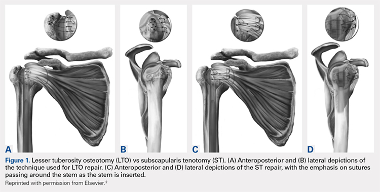
Continue to: LTO was performed as the primary...
LESSER TUBEROSITY OSTEOTOMY
LTO was performed as the primary or preferred technique of 1 surgeon. After completion of the biceps tenodesis, the lesser tuberosity is reflected off with the subscapularis intact using an osteotome. After placement of the press-fit humeral stem, the LTO is repaired using No. 5 Ethibond Excel sutures (Ethicon) passed through previously created bone tunnels in the greater tuberosity. These sutures are tied over metal buttons over the lateral cortex of the greater tuberosity. Last, the lateral corner of the rotator interval is repaired using a single No. 2 FiberWire (Arthrex).2
SUBSCAPULARIS TENOTOMY
ST is the preferred surgical technique of the second surgeon. After a biceps tenodesis, the subscapularis tendon is released from the lesser tuberosity at the margin of the bicipital groove. Through careful dissection, a single flap including the underlying capsule is created and reflected medially to the level of the coracoid. After placement of the press-fit humeral stem and humeral head, the subscapularis is repaired back in place through previous bone tunnels and with a No. 5 Ethibond Excel suture under the appropriate tension. Then, the lateral corner of the rotator interval is closed using a single No. 2 Ethibond Excel suture in a figure-of-eight fashion.2
RADIOGRAPHIC ANALYSIS
The primary variables analyzed were subsidence and loosening. Additional variables, including humeral-acromial distance (HAD) and subluxation index, were also analyzed to assess for any additional impact caused by subsidence or loosening.3 All radiographic measurements were taken from the Grashey (true anteroposterior) view, except subluxation index, which was calculated using the axillary view. All radiographic measurements were completed by 3 independent reviewers. All radiographs were completed in a consistent manner according to postoperative protocols.
HAD was measured preoperatively, immediately postoperatively, and at final follow-up at a minimum of 1 year. The HAD was measured from the lowest point on the acromion to the humerus using a perpendicular line (Figure 2). 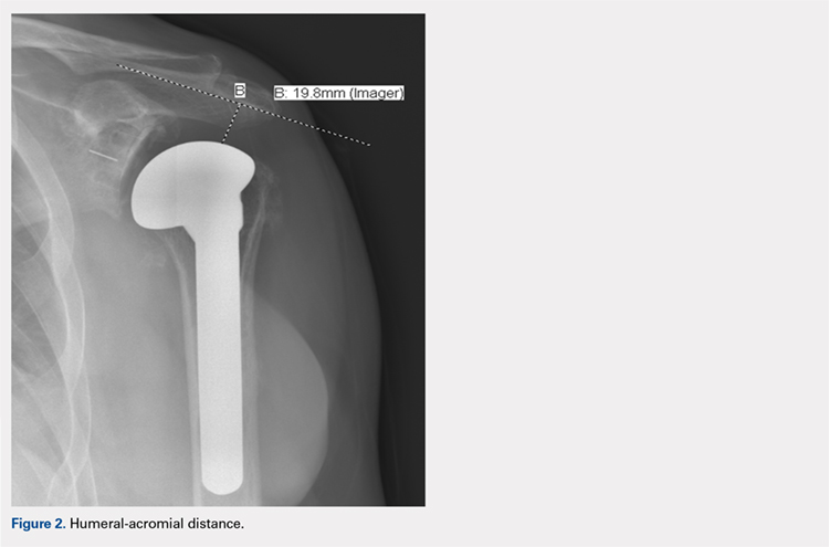
Subsidence of the prosthesis was calculated by determining the difference between immediate postoperative heights of the prosthesis in comparison to the value of the final follow-up films. To calculate the height, 2 lines were drawn, 1 line was drawn perpendicular to the top of the prosthetic head and 1 perpendicular to the top of the greater tuberosity (Figure 3). 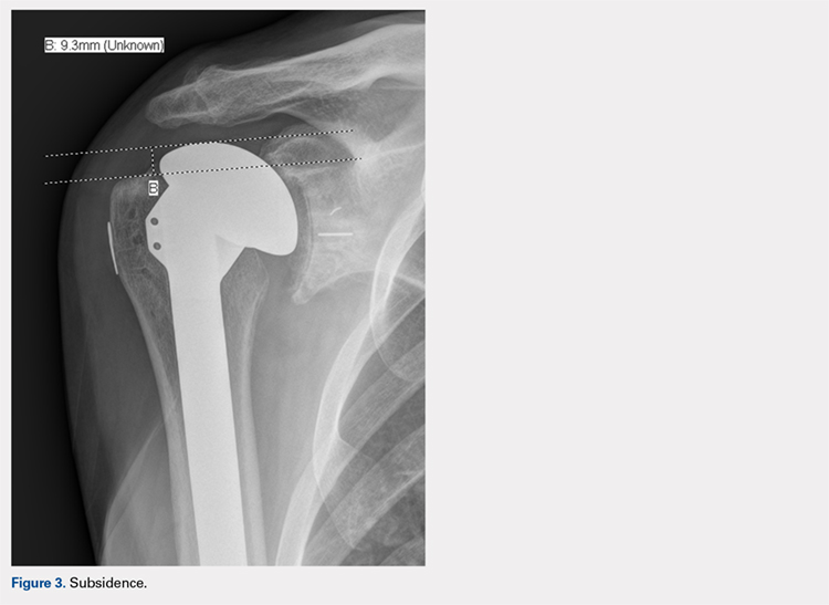
Continue to: Posterior subluxation is indicated...
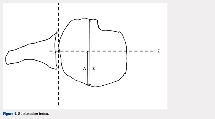
Posterior subluxation is indicated by a value >65%, a centered head is between 35% and 65%, and anterior subluxation is indicated by a value <35% (Figure 4).3
The humeral stems were evaluated for loosening by assessing for lucency on final radiographic follow-up films. These were evaluated in a zonal fashion as demonstrated by Sanchez-Sotelo and colleagues4 and in Figure 5. 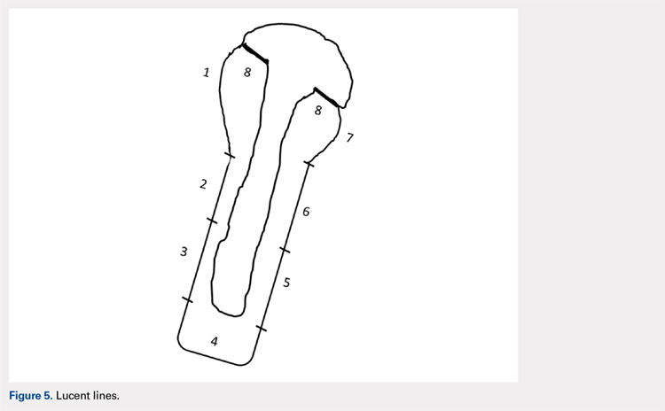
FUNCTIONAL OUTCOME EVALUATION
Before clinical evaluation, each study patient completed the Western Ontario Osteoarthritis of the Shoulder (WOOS) index; the Disabilities of the Hand, Arm and Shoulder (DASH) questionnaire, and the pain and function sections of the Constant score. The functional outcomes scores were captured postoperatively from October to November 2011. The WOOS is a validated outcome measure specific to osteoarthritis of the shoulder and has been used in prior studies evaluating outcomes of TSA.5-7 Previous studies have determined that the minimal clinically important difference for the WOOS score is 15 on a normalized 0 to 100 scale (100 being the best). The DASH score is a validated outcome measure for disorders of the upper extremity but is not specific to osteoarthritis of the shoulder.8 The Constant score is a validated outcome measure for a number of shoulder disorders, including TSA.9,10
STATISTICAL ANALYSIS
Statistical analyses were completed by a trained biostatistician. A power analysis was calculated using the noninferiority test to determine if adequate data had been obtained for this study. This was calculated by using previously accepted data demonstrating a statistically significant difference for subsidence and HAD. The data from these studies were used to make assumptions regarding accepted standard deviations and noninferiority margins, as calculated from the mean values of the 2 groups analyzed in each respective study.4,11 This analysis demonstrated power of 0.97 and 0.85 for the subsidence and HAD, respectively, given the current sample sizes. Intraclass coefficients were calculated to evaluate the measurements obtained during the radiographic analysis to determine the interrater agreement. Two samples’ t tests were calculated for the variables analyzed, along with P values and means.
RESULTS
DEMOGRAPHICS
A total of 51 consecutive patients were retrospectively selected for analysis. Of these, 16 patients were excluded from the study because they had <9 months of radiographic follow-up and were unavailable for further follow-up evaluation. Of the remaining 35 patients available for analysis, 4 patients had bilateral TSA, providing 39 shoulders for evaluation. Demographic characteristics of the study cohort are reported in Table 1.
| Table 1. Demographic Characteristics | |||
| Tenotomy (n = 24) | Osteotomy (n = 15) | P-value | |
| Age | 68.2 [7.4] | 70.2 [7.1] | 0.46 |
| Follow-up | 20.6 [11.5] | 18.5 [6.25] | 0.94 |
| Females | 7 (29%) | 6 (40%) | 0.58 |
| Dominant shoulder | 14 (58%) | 8 (53%) | 0.81 |
| Primary Diagnosis | |||
| Osteoarthritis | 22 (92%) | 15 (100%) | |
| Rheumatoid arthritis | 2 (8%) | 0 (0%) |
Fifteen patients underwent LTO, and 24 underwent ST. One patient underwent a tenotomy of the right shoulder and LTO of the left shoulder. Three LTOs were performed by the surgeon who primarily performed ST, owing to potential benefits of LTO. He eventually returned to his preferred technique of ST because of surgeon preference. Three ST procedures were completed by the surgeon who typically performed LTO at the start of the series prior to establishing LTO as his preferred technique. There was no significant difference between the study populations in terms of age, follow-up, male-to-female ratio, hand dominance, and primary diagnosis of osteoarthritis vs rheumatoid arthritis.
Continue to: There was no significant difference...
RADIOGRAPHIC DATA
There was no significant difference in preoperative HAD between the LTO and ST groups (9.5 ± 2.4 mm vs 10.9 ± 2.7 mm, P = .11). The immediate postoperative HAD was statistically significant between the LTO and ST groups (11.9 ± 3.7 mm vs 15.9 ± 4.5 mm, P = .005). There was as statistically significant difference noted in the final follow-up films between the LTO and ST groups (11.8 ± 3.2 mm vs 14.5 ± 3.9 mm, P = .025) (Table 2).
Table 2. Radiographic Data | |||||
Humeral Acromial Distance | |||||
| LTO | ST | P-Value | ||
Preoperative, mm | 9.5 | [2.4] | 10.9 | [2.7] | 0.11 |
Postoperative, mm | 11.9 | [3.7] | 15.9 | [4.5] | 0.005 |
Final follow-up, mm | 11.8 | [3.2] | 14.5 | [3.9] | 0.025 |
Subsidence | |||||
| LTO | ST | P-Value | ||
Subsidence, mm | 2.8 | [3.1] | 2.5 | [3.1] | 0.72 |
Subluxation Index | |||||
| LTO | ST | P-Value | ||
Preoperative, % | 0.55 | [0.06] | 0.54 | [0.07] | 0.45 |
Postoperative, % | 0.55 | [0.09] | 0.48 | [0.05] | 0.015 |
Lucent Lines | |||||
| LTO | ST | P-Value | ||
Lines >2 mm, % | 0.00 | 0.08 | 0.51 | ||
Abbreviations: LTO, lesser tuberosity osteotomy; ST, subscapularis tenotomy.
There were no statistically significant differences found in subsidence between LTO and ST groups at final follow-up (2.8 mm ± 3.1 mm vs 2.5 mm ± 3.1 mm, P = .72) (Table 2). No statistically significant difference was noted in the subluxation index between the LTO and ST groups (0.55% ± .06% vs 0.54% ± 0.07%, P = .45), but there was a statistically significant difference noted postoperatively between the LTO and ST groups (0.55% ± 0.09% vs .48% ± 0.05%, P = .015) (Table 2).
Two stems were noted to have lucent lines >2 mm, both within the ST cohort. Each had 1 stem zone >2 mm, 1 in zone 7, and 1 in zone 4. No statistically significant difference was identified between the LTO and ST groups (0/15 vs 2/24, P = .51) (Table 2).
FUNCTIONAL OUTCOMES
Study patients were evaluated using functional outcome scores, including the Constant, WOOS, and DASH scores (Table 3).
| Table 3. Functional Data | |||||
| LTO | ST | P-Value | |||
| WOOS index | 93.3 | [5.3] | 81.5 | [20.8] | 0.013 |
| DASH score | 8.4 | [6.6] | 13.8 | [4.9] | 0.13 |
| Constant score | 83.3 | [9.1] | 81.8 | [10.1] | 0.64 |
Abbreviations: DASH, disabilities of the arm, shoulder and hand; WOOS, Western Ontario Osteoarthritis of the Shoulder.
No statistically significant differences were noted in the DASH scores (8.4 ± 6.6 vs 13.8 ± 4.9, P = .13) or Constant scores (83.3 ± 9.1 vs 81.8 ± 10.1, P = .64) between the LTO and ST cohorts. There was a statistically significant difference between the WOOS scores (93.3 ± 5.3 vs 81.5 ± 20.8, P = .013). Because separate radiographic reviews were done by 3 independent personnel at 3 different times, it was important to ensure agreement among the reviewers. This was compared using the intraclass correlation coefficients. In the statistical analysis completed, the intraclass coefficients showed the 3 reviewers agreed with each other throughout the radiographic analysis (Table 4).
| Table 4. Testing Agreement: ICC | ||||
| ICC | CI, 2.5% | CI, 97.5% | ||
| HAD | Preoperative | 0.4451 | 0.2202 | 0.6443 |
| Postoperative | 0.6997 | 0.4836 | 0.834 | |
| Final follow-up | 0.5575 | 0.3592 | 0.7218 | |
| Subsidence | 0.6863 | 0.5349 | 0.807 | |
| SI | Preoperative | 0.3087 | 0.1061 | 0.5213 |
| Final follow-up | 0.5364 | 0.299 | 0.7186 |
Abbreviations: CI, confidence interval; HAD, humeral acromial distance; ICC, intraclass correlation coefficient; SI, subluxation index.
DISCUSSION
At final follow-up, we identified no statistically significant difference between the LTO and ST patients in subsidence, lucent lines >2 mm, or functional outcomes (Constant and DASH scores) in patients who underwent TSA with the same proximal collar press-fit humeral stem. In regard to the functional outcome scores, although the WOOS score was statistically significant (P = .013) between the LTO and ST cohorts, we do not feel that this is clinically relevant because it does not reach the minimal clinically important difference threshold of 15 points.8
A statistically significant difference was noted in postoperative subluxation index but was not clinically relevant, because the values between the LTO and ST groups (0.55 vs 0.48) still showed a centered humeral head. Gerber and colleagues3 discussed using a value of 0.65 as a measure of posterior humeral head subluxation, whereas Walch and colleagues12 defined posterior humeral head subluxation as a value >0.55. On the basis of these numbers, the values obtained in this study demonstrated that the postoperative values were still centered on the glenoid, and therefore were not clinically significant.3,12
Continue to: In regard to HAD, there...
In regard to HAD, there was a statistically significant difference noted postoperatively (P = .005) and at final follow-up (P = .025) between the LTO and ST cohorts. Saupe and colleagues13 demonstrated that a HAD <7 mm was considered abnormal and reflected subacromial space narrowing. The values noted in the LTO and ST patients on postoperative and final follow-up radiographs were statistically significant (Table 2), but not clinically relevant because both were >7 mm. A potential source for the variation in HAD may be due to X-ray position and angle.
Studies have shown a concern regarding the integrity of the subscapularis after tenotomy or peel used in TSA with abnormal subscapularis function.14,15 Miller and colleagues15 reported 41 patients, nearly two-thirds, of whom described subscapularis dysfunction. Those authors’ response to the poor clinical outcomes was to remove a fleck of bone with the tendon to achieve “bone-to-bone” healing.14 Gerber and colleagues16 reported on a series of patients using LTO and repair in TSA with 75% and 89% intact subscapularis function on clinical testing.16 Studies by Qureshi and colleagues17 and Scalise and colleagues18 showed similar results after LTO. Biomechanical studies have shown mixed results. Ponce and colleagues19 showed biomechanically superior results for LTO in comparison to the various repair techniques for ST. In another study, Giuseffi and colleagues20 showed no difference in LTO vs ST during biomechanical testing. In response to the increased concern regarding subscapularis integrity, Caplan and colleagues21 reported on 45 arthroplasties in 43 patients with improved postoperative testing with intact subscapularis testing in 90% to 100% of patients. A level 1 randomized control trial conducted by Lapner and colleagues22 did not demonstrate any clear clinical advantage of LTO vs ST. Controversy still exists regarding which is the preferred technique for TSA.
Sanchez-Sotelo and colleagues4 evaluated uncemented humeral components in 72 patients who underwent TSA. They found a humeral component was at risk for loosening if a radiolucent line ≥2 mm was present in at least 3 radiographic zones. They also evaluated tilt or subsidence by measurement and whether the components were observed to have changed. Their measured values correlated with their observed values. That study provided a benchmark for evaluation of loosening and subsidence used during this study.4 Although radiographic follow-up is limited in this study, we feel that any potential subsidence secondary to use of the LTO technique would be radiographically apparent at 1 year. There were 16 patients without adequate radiographic follow-up included in the study. However, we feel that this was not a large concern, because the study was adequately powered with the patients available to determine a difference based on subsidence.
CONCLUSION
We found no difference in subsidence, lucent lines >2 mm, posterior subluxation, and the Constant and DASH functional outcome scores when we compared TSA performed by a LTO with an ST technique with proximal collar press-fit humeral stem. These data cannot be extrapolated to metaphyseal fit stems, which may exhibit different settling characteristics in the setting of the LTO technique.
This paper will be judged for the Resident Writer’s Award.
1. Blasier R, Soslowsky L, Malicky D, Palmer M. Posterior glenohumeral subluxation: Active and passive stabilization in a biomechanical model. J Bone Joint Surg Am. 1997;79-A(3):433-440.
2. Buckley T, Miller R, Nicandri G, Lewis R, Voloshin I. Analysis of subscapularis integrity and function after lesser tuberosity osteotomy versus subscapularis tenotomy in total shoulder arthroplasty using ultrasound and validated clinical outcome measures. J Shoulder Elbow Surg. 2014;23(9):1309-1317. doi:10.1016/j.jse.2013.12.009.
3. Gerber C, Costouros JG, Sukthankar A, Fucentese SF. Static posterior humeral head subluxation and total shoulder arthroplasty. J Shoulder Elbow Surg. 2009;18(4):505-510. doi:10.1016/j.jse.2009.03.003.
4. Sanchez-Sotelo J, Wright TW, O'Driscoll SW, Cofield RH, Rowland CM. Radiographic assessment of uncemented humeral components in total shoulder arthroplasty. J Arthroplasty. 2001;16(2):180-187.
5. Litchfield RB, McKee MD, Balyk R, et al. Cemented versus uncemented fixation of humeral components in total shoulder arthroplasty for osteoarthrtitis of the shoulder: A prospective, randomized, double-blind clinical trial-A JOINTs Canada Project. J Shoulder Elbow Surg. 2013;20(4):529-536. doi:10.1016/j.jse.2011.01.041.
6. Lo IK, Griffin S, Kirkley A. The development of a disease specific quality of life measurement tool for osteoarthritis of the shoulder: The Western Ontario Osteoarthritis of the Shoulder (WOOS) index. Osteoarthritis Cartilage. 2001;9(8):771-778. doi:10.1053/joca.2001.0474
7. Lo IK, Litchfield RB, Griffin S, Faber K, Patterson SD, Kirkley A. Quality of life outcome following hemiarthroplasty or total shoulder arthroplasty in patients with osteoarthritis. A prospective, randomized trial. J Bone Joint Surg Am. 2005;87(10):2178-2185. doi:10.2106/JBJS.D.02198
8. Hudak PL, Amadio PC, Bombardier C. Development of an upper extremity outcome measure: the DASH (disabilities of the arm, shoulder and hand) [corrected]. The Upper Extremity Collaborative Group (UECG). Am J Ind Med. 1996;29(6):602-608. doi:10.1002/(SICI)1097-0274(199606)29:6<602::AID-AJIM4>3.0.CO;2-L.
9. Constant CR, Gerber C, Emery RJ, Sojbjerg JO, Gohlke F, Boileau P. A review of the constant score: Modifications and guidelines for its use. J Shoulder Elbow Surg. 2008;17(2):355-361. doi:10.1016/j.jse.2007.06.022.
10. Constant CR, Murley AH. A clinical method of functional assessment of the shoulder. Clin Orthop Relat Res. 1987;(214):160-164.
11. Mayerhoefer ME, Breitenseher MJ, Wurnig C, Roposch A. Shoulder impingement: Relationship of clinical symptoms and imaging criteria. Clin J Sport Med. 2009;19(2):83-89. doi:10.1097/JSM.0b013e318198e2e3.
12. Walch G, Badet R, Boulahia A, Khoury A. Morphologic study of the glenoid in primary glenohumeral osteoarthritis. J Arthroplasy. 1999;14(6):756-760.
13. Saupe N, Pfirmann CW, Schmid MR, et al. Association between rotator cuff abnormalities and reduced acromiohumeral distance. AJR Am J Roentgenol. 2006;187(2):376-382. doi:10.2214/AJR.05.0435.
14. Jackson J, Cil A, Smith J, Steinmann SP. Integrity and function of the subscapularis after total shoulder arthroplasty. J Shoulder Elbow Surg. 2010;19(7):1085-1090. doi:10.1016/j.jse.2010.04.001.
15. Miller SL, Hazrati Y, Klepps S, Chiang A, Flatow EL. Loss of subscapularis function after total shoulder replacement: a seldom recognized problem. J Shoulder Elbow Surg. 2003;12(1):29-34. doi:10.1067/mse.2003.128195.
16. Gerber C, Yian EH, Pfirrmann AW, Zumstein MA, Werner CM. Subscapularis muscle function and structure after total shoulder replacement with lesser tuberosity osteotomy and repair. J Bone Joint Surg Am. 2005;87(8):1739-1745. doi:10.2106/JBJS.D.02788.
17. Qureshi S, Hsiao A, Klug RA, Lee E, Braman J, Flatow EL. Subscapularis function after total shoulder replacement: results with lesser tuberosity osteotomy. J Shoulder Elbow Surg. 2008;17(1): 68-72. doi:10.1016/j.jse.2007.04.018.
18. Scalise JJ, Ciccone J, Iannotti JP. Clinical, radiographic and ultrasonographic comparison of subscapularis tenotomy and lesser tuberosity osteotomy for total shoulder arthroplasty. J Bone Joint Surg Am. 2010;92(7):1627-1634. doi:10.2106/JBJS.G.01461.
19. Ponce BA, Ahluwalia RS, Mazzocca AD, Gobezie RG, Warner JJ, Millett PJ. Biomechanical and clinical evaluation of a novel lesser tuberosity in total shoulder arthroplasty. J Bone Joint Surg Am. 2005;87 Suppl 2:1-8.
20. Giuseffi SA, Wongtriratanachai P, Omae H, et al. Biomechanical comparison of lesser tuberosity osteotomy versus subscapularis tenotomy in total shoulder arthroplasty. J Shoulder Elbow Surg. 2012;21(8):1087-1095. doi:10.1016/j.jse.2011.07.008.
21. Caplan JL, Whitfield W, Nevasier RJ. Subscapularis function after primary tendon to tendon repair in patients after replacement arthroplasty of the shoulder. J Shoulder Elbow Surg. 2009;18(2):193-196. doi:10.1016/j.jse.2008.10.019.
22. Lapner PLC, Sabri E, Rakhra K, Bell K, Athwal GS. Comparison of LTO to subscapularis peel in shoulder arthroplasty. J Bone Joint Surg Am. 2012;94(24):2239-2246. doi:10.2106/JBJS.K.01365.
ABSTRACT
Lesser tuberosity osteotomy (LTO) and subscapularis tenotomy (ST) are used for takedown of the subscapularis during shoulder arthroplasty. LTO offers the theoretical but unproven benefit of improved healing and function of the subscapularis. However, humeral stem subsidence and loosening may be greater when osteotomy is performed, which may compromise functional outcomes. Our hypothesis is that no difference in proximal collar press-fit humeral stem subsidence or loosening exists, with no impairment of functional outcomes using the LTO technique.
During the surgical approach for total shoulder arthroplasty (TSA), the subscapularis is taken down for adequate exposure to the glenohumeral joint. Various methods are available for taking down the subscapularis, including lesser tuberosity osteotomy (LTO) and a subscapularis tenotomy (ST). LTO offers the theoretical but unproven benefit of improved healing and function of the subscapularis secondary to bone-to-bone healing. One concern, however, is that humeral stem subsidence may be greater when an osteotomy is performed owing to compromise of metaphyseal cortical bone, which may compromise functional outcomes. The humeral stem design may also influence subsidence when metaphyseal bone proximally is compromised. This is a concern in both metaphyseal and diaphyseal fitting stems. Metaphyseal collars on diaphyseal fitting stems rely on adequate bone stock in the metaphysis to provide the additional support needed. Also, posterior subluxation remains a challenge in shoulder arthroplasty. The integrity of the subscapularis is important in prevention of posterior subluxation.1 To our knowledge, no study to date has directly compared differences in humeral stem subsidence, loosening, or posterior subluxation between LTO and ST techniques with any humeral stem design. Our hypothesis is that no difference in proximal collar press-fit humeral stem subsidence or loosening exists, with no impairment of functional outcomes using the LTO technique. We also hypothesize that no difference in posterior subluxation exists between LTO and ST techniques.
MATERIALS AND METHODS
INCLUSION CRITERIA
Consecutive patients with a minimum of 12 months of radiographic follow-up were selected from 2007 to 2010 after TSA was performed by 1 of the senior authors (Dr. Miller and Dr. Voloshin). Study patients underwent primary TSA for primary osteoarthritis or rheumatoid arthritis.
EXCLUSION CRITERIA
Patients were excluded if they underwent TSA for posttraumatic glenohumeral arthritis, hemiarthroplasty, or osteonecrosis. Patients were also excluded if a rotator cuff tear was discovered intraoperatively or if they had a history of a rotator cuff repair. Additional exclusion criteria included postoperative trauma to the operative shoulder, postoperative infection, extensive documentation of chronic pain, and underlying neurologic disorder (eg, Parkinson disease, dystonia). Patients with a history of diabetes mellitus were not excluded.
SURGICAL TECHNIQUE
All patients underwent TSA via a deltopectoral approach in a modified beach chair position. Biceps tendons were tenodesed at the level of the pectoralis major. All patients received the same proximal collar press-fit implant (Bigliani-Flatow; Zimmer Biomet). These stems provide rotational stability in the metaphyseal segment via fins, vertical stability with the proximal collar, and distal fixation via an interference fit. All parts of the procedure were performed in similar fashion with the exception of ST vs LTO (Figures 1A-1D).
Continue to: LTO was performed as the primary...
LESSER TUBEROSITY OSTEOTOMY
LTO was performed as the primary or preferred technique of 1 surgeon. After completion of the biceps tenodesis, the lesser tuberosity is reflected off with the subscapularis intact using an osteotome. After placement of the press-fit humeral stem, the LTO is repaired using No. 5 Ethibond Excel sutures (Ethicon) passed through previously created bone tunnels in the greater tuberosity. These sutures are tied over metal buttons over the lateral cortex of the greater tuberosity. Last, the lateral corner of the rotator interval is repaired using a single No. 2 FiberWire (Arthrex).2
SUBSCAPULARIS TENOTOMY
ST is the preferred surgical technique of the second surgeon. After a biceps tenodesis, the subscapularis tendon is released from the lesser tuberosity at the margin of the bicipital groove. Through careful dissection, a single flap including the underlying capsule is created and reflected medially to the level of the coracoid. After placement of the press-fit humeral stem and humeral head, the subscapularis is repaired back in place through previous bone tunnels and with a No. 5 Ethibond Excel suture under the appropriate tension. Then, the lateral corner of the rotator interval is closed using a single No. 2 Ethibond Excel suture in a figure-of-eight fashion.2
RADIOGRAPHIC ANALYSIS
The primary variables analyzed were subsidence and loosening. Additional variables, including humeral-acromial distance (HAD) and subluxation index, were also analyzed to assess for any additional impact caused by subsidence or loosening.3 All radiographic measurements were taken from the Grashey (true anteroposterior) view, except subluxation index, which was calculated using the axillary view. All radiographic measurements were completed by 3 independent reviewers. All radiographs were completed in a consistent manner according to postoperative protocols.
HAD was measured preoperatively, immediately postoperatively, and at final follow-up at a minimum of 1 year. The HAD was measured from the lowest point on the acromion to the humerus using a perpendicular line (Figure 2).
Subsidence of the prosthesis was calculated by determining the difference between immediate postoperative heights of the prosthesis in comparison to the value of the final follow-up films. To calculate the height, 2 lines were drawn, 1 line was drawn perpendicular to the top of the prosthetic head and 1 perpendicular to the top of the greater tuberosity (Figure 3).
Continue to: Posterior subluxation is indicated...
Posterior subluxation is indicated by a value >65%, a centered head is between 35% and 65%, and anterior subluxation is indicated by a value <35% (Figure 4).3
The humeral stems were evaluated for loosening by assessing for lucency on final radiographic follow-up films. These were evaluated in a zonal fashion as demonstrated by Sanchez-Sotelo and colleagues4 and in Figure 5.
FUNCTIONAL OUTCOME EVALUATION
Before clinical evaluation, each study patient completed the Western Ontario Osteoarthritis of the Shoulder (WOOS) index; the Disabilities of the Hand, Arm and Shoulder (DASH) questionnaire, and the pain and function sections of the Constant score. The functional outcomes scores were captured postoperatively from October to November 2011. The WOOS is a validated outcome measure specific to osteoarthritis of the shoulder and has been used in prior studies evaluating outcomes of TSA.5-7 Previous studies have determined that the minimal clinically important difference for the WOOS score is 15 on a normalized 0 to 100 scale (100 being the best). The DASH score is a validated outcome measure for disorders of the upper extremity but is not specific to osteoarthritis of the shoulder.8 The Constant score is a validated outcome measure for a number of shoulder disorders, including TSA.9,10
STATISTICAL ANALYSIS
Statistical analyses were completed by a trained biostatistician. A power analysis was calculated using the noninferiority test to determine if adequate data had been obtained for this study. This was calculated by using previously accepted data demonstrating a statistically significant difference for subsidence and HAD. The data from these studies were used to make assumptions regarding accepted standard deviations and noninferiority margins, as calculated from the mean values of the 2 groups analyzed in each respective study.4,11 This analysis demonstrated power of 0.97 and 0.85 for the subsidence and HAD, respectively, given the current sample sizes. Intraclass coefficients were calculated to evaluate the measurements obtained during the radiographic analysis to determine the interrater agreement. Two samples’ t tests were calculated for the variables analyzed, along with P values and means.
RESULTS
DEMOGRAPHICS
A total of 51 consecutive patients were retrospectively selected for analysis. Of these, 16 patients were excluded from the study because they had <9 months of radiographic follow-up and were unavailable for further follow-up evaluation. Of the remaining 35 patients available for analysis, 4 patients had bilateral TSA, providing 39 shoulders for evaluation. Demographic characteristics of the study cohort are reported in Table 1.
| Table 1. Demographic Characteristics | |||
| Tenotomy (n = 24) | Osteotomy (n = 15) | P-value | |
| Age | 68.2 [7.4] | 70.2 [7.1] | 0.46 |
| Follow-up | 20.6 [11.5] | 18.5 [6.25] | 0.94 |
| Females | 7 (29%) | 6 (40%) | 0.58 |
| Dominant shoulder | 14 (58%) | 8 (53%) | 0.81 |
| Primary Diagnosis | |||
| Osteoarthritis | 22 (92%) | 15 (100%) | |
| Rheumatoid arthritis | 2 (8%) | 0 (0%) |
Fifteen patients underwent LTO, and 24 underwent ST. One patient underwent a tenotomy of the right shoulder and LTO of the left shoulder. Three LTOs were performed by the surgeon who primarily performed ST, owing to potential benefits of LTO. He eventually returned to his preferred technique of ST because of surgeon preference. Three ST procedures were completed by the surgeon who typically performed LTO at the start of the series prior to establishing LTO as his preferred technique. There was no significant difference between the study populations in terms of age, follow-up, male-to-female ratio, hand dominance, and primary diagnosis of osteoarthritis vs rheumatoid arthritis.
Continue to: There was no significant difference...
RADIOGRAPHIC DATA
There was no significant difference in preoperative HAD between the LTO and ST groups (9.5 ± 2.4 mm vs 10.9 ± 2.7 mm, P = .11). The immediate postoperative HAD was statistically significant between the LTO and ST groups (11.9 ± 3.7 mm vs 15.9 ± 4.5 mm, P = .005). There was as statistically significant difference noted in the final follow-up films between the LTO and ST groups (11.8 ± 3.2 mm vs 14.5 ± 3.9 mm, P = .025) (Table 2).
Table 2. Radiographic Data | |||||
Humeral Acromial Distance | |||||
| LTO | ST | P-Value | ||
Preoperative, mm | 9.5 | [2.4] | 10.9 | [2.7] | 0.11 |
Postoperative, mm | 11.9 | [3.7] | 15.9 | [4.5] | 0.005 |
Final follow-up, mm | 11.8 | [3.2] | 14.5 | [3.9] | 0.025 |
Subsidence | |||||
| LTO | ST | P-Value | ||
Subsidence, mm | 2.8 | [3.1] | 2.5 | [3.1] | 0.72 |
Subluxation Index | |||||
| LTO | ST | P-Value | ||
Preoperative, % | 0.55 | [0.06] | 0.54 | [0.07] | 0.45 |
Postoperative, % | 0.55 | [0.09] | 0.48 | [0.05] | 0.015 |
Lucent Lines | |||||
| LTO | ST | P-Value | ||
Lines >2 mm, % | 0.00 | 0.08 | 0.51 | ||
Abbreviations: LTO, lesser tuberosity osteotomy; ST, subscapularis tenotomy.
There were no statistically significant differences found in subsidence between LTO and ST groups at final follow-up (2.8 mm ± 3.1 mm vs 2.5 mm ± 3.1 mm, P = .72) (Table 2). No statistically significant difference was noted in the subluxation index between the LTO and ST groups (0.55% ± .06% vs 0.54% ± 0.07%, P = .45), but there was a statistically significant difference noted postoperatively between the LTO and ST groups (0.55% ± 0.09% vs .48% ± 0.05%, P = .015) (Table 2).
Two stems were noted to have lucent lines >2 mm, both within the ST cohort. Each had 1 stem zone >2 mm, 1 in zone 7, and 1 in zone 4. No statistically significant difference was identified between the LTO and ST groups (0/15 vs 2/24, P = .51) (Table 2).
FUNCTIONAL OUTCOMES
Study patients were evaluated using functional outcome scores, including the Constant, WOOS, and DASH scores (Table 3).
| Table 3. Functional Data | |||||
| LTO | ST | P-Value | |||
| WOOS index | 93.3 | [5.3] | 81.5 | [20.8] | 0.013 |
| DASH score | 8.4 | [6.6] | 13.8 | [4.9] | 0.13 |
| Constant score | 83.3 | [9.1] | 81.8 | [10.1] | 0.64 |
Abbreviations: DASH, disabilities of the arm, shoulder and hand; WOOS, Western Ontario Osteoarthritis of the Shoulder.
No statistically significant differences were noted in the DASH scores (8.4 ± 6.6 vs 13.8 ± 4.9, P = .13) or Constant scores (83.3 ± 9.1 vs 81.8 ± 10.1, P = .64) between the LTO and ST cohorts. There was a statistically significant difference between the WOOS scores (93.3 ± 5.3 vs 81.5 ± 20.8, P = .013). Because separate radiographic reviews were done by 3 independent personnel at 3 different times, it was important to ensure agreement among the reviewers. This was compared using the intraclass correlation coefficients. In the statistical analysis completed, the intraclass coefficients showed the 3 reviewers agreed with each other throughout the radiographic analysis (Table 4).
| Table 4. Testing Agreement: ICC | ||||
| ICC | CI, 2.5% | CI, 97.5% | ||
| HAD | Preoperative | 0.4451 | 0.2202 | 0.6443 |
| Postoperative | 0.6997 | 0.4836 | 0.834 | |
| Final follow-up | 0.5575 | 0.3592 | 0.7218 | |
| Subsidence | 0.6863 | 0.5349 | 0.807 | |
| SI | Preoperative | 0.3087 | 0.1061 | 0.5213 |
| Final follow-up | 0.5364 | 0.299 | 0.7186 |
Abbreviations: CI, confidence interval; HAD, humeral acromial distance; ICC, intraclass correlation coefficient; SI, subluxation index.
DISCUSSION
At final follow-up, we identified no statistically significant difference between the LTO and ST patients in subsidence, lucent lines >2 mm, or functional outcomes (Constant and DASH scores) in patients who underwent TSA with the same proximal collar press-fit humeral stem. In regard to the functional outcome scores, although the WOOS score was statistically significant (P = .013) between the LTO and ST cohorts, we do not feel that this is clinically relevant because it does not reach the minimal clinically important difference threshold of 15 points.8
A statistically significant difference was noted in postoperative subluxation index but was not clinically relevant, because the values between the LTO and ST groups (0.55 vs 0.48) still showed a centered humeral head. Gerber and colleagues3 discussed using a value of 0.65 as a measure of posterior humeral head subluxation, whereas Walch and colleagues12 defined posterior humeral head subluxation as a value >0.55. On the basis of these numbers, the values obtained in this study demonstrated that the postoperative values were still centered on the glenoid, and therefore were not clinically significant.3,12
Continue to: In regard to HAD, there...
In regard to HAD, there was a statistically significant difference noted postoperatively (P = .005) and at final follow-up (P = .025) between the LTO and ST cohorts. Saupe and colleagues13 demonstrated that a HAD <7 mm was considered abnormal and reflected subacromial space narrowing. The values noted in the LTO and ST patients on postoperative and final follow-up radiographs were statistically significant (Table 2), but not clinically relevant because both were >7 mm. A potential source for the variation in HAD may be due to X-ray position and angle.
Studies have shown a concern regarding the integrity of the subscapularis after tenotomy or peel used in TSA with abnormal subscapularis function.14,15 Miller and colleagues15 reported 41 patients, nearly two-thirds, of whom described subscapularis dysfunction. Those authors’ response to the poor clinical outcomes was to remove a fleck of bone with the tendon to achieve “bone-to-bone” healing.14 Gerber and colleagues16 reported on a series of patients using LTO and repair in TSA with 75% and 89% intact subscapularis function on clinical testing.16 Studies by Qureshi and colleagues17 and Scalise and colleagues18 showed similar results after LTO. Biomechanical studies have shown mixed results. Ponce and colleagues19 showed biomechanically superior results for LTO in comparison to the various repair techniques for ST. In another study, Giuseffi and colleagues20 showed no difference in LTO vs ST during biomechanical testing. In response to the increased concern regarding subscapularis integrity, Caplan and colleagues21 reported on 45 arthroplasties in 43 patients with improved postoperative testing with intact subscapularis testing in 90% to 100% of patients. A level 1 randomized control trial conducted by Lapner and colleagues22 did not demonstrate any clear clinical advantage of LTO vs ST. Controversy still exists regarding which is the preferred technique for TSA.
Sanchez-Sotelo and colleagues4 evaluated uncemented humeral components in 72 patients who underwent TSA. They found a humeral component was at risk for loosening if a radiolucent line ≥2 mm was present in at least 3 radiographic zones. They also evaluated tilt or subsidence by measurement and whether the components were observed to have changed. Their measured values correlated with their observed values. That study provided a benchmark for evaluation of loosening and subsidence used during this study.4 Although radiographic follow-up is limited in this study, we feel that any potential subsidence secondary to use of the LTO technique would be radiographically apparent at 1 year. There were 16 patients without adequate radiographic follow-up included in the study. However, we feel that this was not a large concern, because the study was adequately powered with the patients available to determine a difference based on subsidence.
CONCLUSION
We found no difference in subsidence, lucent lines >2 mm, posterior subluxation, and the Constant and DASH functional outcome scores when we compared TSA performed by a LTO with an ST technique with proximal collar press-fit humeral stem. These data cannot be extrapolated to metaphyseal fit stems, which may exhibit different settling characteristics in the setting of the LTO technique.
This paper will be judged for the Resident Writer’s Award.
1. Blasier R, Soslowsky L, Malicky D, Palmer M. Posterior glenohumeral subluxation: Active and passive stabilization in a biomechanical model. J Bone Joint Surg Am. 1997;79-A(3):433-440.
2. Buckley T, Miller R, Nicandri G, Lewis R, Voloshin I. Analysis of subscapularis integrity and function after lesser tuberosity osteotomy versus subscapularis tenotomy in total shoulder arthroplasty using ultrasound and validated clinical outcome measures. J Shoulder Elbow Surg. 2014;23(9):1309-1317. doi:10.1016/j.jse.2013.12.009.
3. Gerber C, Costouros JG, Sukthankar A, Fucentese SF. Static posterior humeral head subluxation and total shoulder arthroplasty. J Shoulder Elbow Surg. 2009;18(4):505-510. doi:10.1016/j.jse.2009.03.003.
4. Sanchez-Sotelo J, Wright TW, O'Driscoll SW, Cofield RH, Rowland CM. Radiographic assessment of uncemented humeral components in total shoulder arthroplasty. J Arthroplasty. 2001;16(2):180-187.
5. Litchfield RB, McKee MD, Balyk R, et al. Cemented versus uncemented fixation of humeral components in total shoulder arthroplasty for osteoarthrtitis of the shoulder: A prospective, randomized, double-blind clinical trial-A JOINTs Canada Project. J Shoulder Elbow Surg. 2013;20(4):529-536. doi:10.1016/j.jse.2011.01.041.
6. Lo IK, Griffin S, Kirkley A. The development of a disease specific quality of life measurement tool for osteoarthritis of the shoulder: The Western Ontario Osteoarthritis of the Shoulder (WOOS) index. Osteoarthritis Cartilage. 2001;9(8):771-778. doi:10.1053/joca.2001.0474
7. Lo IK, Litchfield RB, Griffin S, Faber K, Patterson SD, Kirkley A. Quality of life outcome following hemiarthroplasty or total shoulder arthroplasty in patients with osteoarthritis. A prospective, randomized trial. J Bone Joint Surg Am. 2005;87(10):2178-2185. doi:10.2106/JBJS.D.02198
8. Hudak PL, Amadio PC, Bombardier C. Development of an upper extremity outcome measure: the DASH (disabilities of the arm, shoulder and hand) [corrected]. The Upper Extremity Collaborative Group (UECG). Am J Ind Med. 1996;29(6):602-608. doi:10.1002/(SICI)1097-0274(199606)29:6<602::AID-AJIM4>3.0.CO;2-L.
9. Constant CR, Gerber C, Emery RJ, Sojbjerg JO, Gohlke F, Boileau P. A review of the constant score: Modifications and guidelines for its use. J Shoulder Elbow Surg. 2008;17(2):355-361. doi:10.1016/j.jse.2007.06.022.
10. Constant CR, Murley AH. A clinical method of functional assessment of the shoulder. Clin Orthop Relat Res. 1987;(214):160-164.
11. Mayerhoefer ME, Breitenseher MJ, Wurnig C, Roposch A. Shoulder impingement: Relationship of clinical symptoms and imaging criteria. Clin J Sport Med. 2009;19(2):83-89. doi:10.1097/JSM.0b013e318198e2e3.
12. Walch G, Badet R, Boulahia A, Khoury A. Morphologic study of the glenoid in primary glenohumeral osteoarthritis. J Arthroplasy. 1999;14(6):756-760.
13. Saupe N, Pfirmann CW, Schmid MR, et al. Association between rotator cuff abnormalities and reduced acromiohumeral distance. AJR Am J Roentgenol. 2006;187(2):376-382. doi:10.2214/AJR.05.0435.
14. Jackson J, Cil A, Smith J, Steinmann SP. Integrity and function of the subscapularis after total shoulder arthroplasty. J Shoulder Elbow Surg. 2010;19(7):1085-1090. doi:10.1016/j.jse.2010.04.001.
15. Miller SL, Hazrati Y, Klepps S, Chiang A, Flatow EL. Loss of subscapularis function after total shoulder replacement: a seldom recognized problem. J Shoulder Elbow Surg. 2003;12(1):29-34. doi:10.1067/mse.2003.128195.
16. Gerber C, Yian EH, Pfirrmann AW, Zumstein MA, Werner CM. Subscapularis muscle function and structure after total shoulder replacement with lesser tuberosity osteotomy and repair. J Bone Joint Surg Am. 2005;87(8):1739-1745. doi:10.2106/JBJS.D.02788.
17. Qureshi S, Hsiao A, Klug RA, Lee E, Braman J, Flatow EL. Subscapularis function after total shoulder replacement: results with lesser tuberosity osteotomy. J Shoulder Elbow Surg. 2008;17(1): 68-72. doi:10.1016/j.jse.2007.04.018.
18. Scalise JJ, Ciccone J, Iannotti JP. Clinical, radiographic and ultrasonographic comparison of subscapularis tenotomy and lesser tuberosity osteotomy for total shoulder arthroplasty. J Bone Joint Surg Am. 2010;92(7):1627-1634. doi:10.2106/JBJS.G.01461.
19. Ponce BA, Ahluwalia RS, Mazzocca AD, Gobezie RG, Warner JJ, Millett PJ. Biomechanical and clinical evaluation of a novel lesser tuberosity in total shoulder arthroplasty. J Bone Joint Surg Am. 2005;87 Suppl 2:1-8.
20. Giuseffi SA, Wongtriratanachai P, Omae H, et al. Biomechanical comparison of lesser tuberosity osteotomy versus subscapularis tenotomy in total shoulder arthroplasty. J Shoulder Elbow Surg. 2012;21(8):1087-1095. doi:10.1016/j.jse.2011.07.008.
21. Caplan JL, Whitfield W, Nevasier RJ. Subscapularis function after primary tendon to tendon repair in patients after replacement arthroplasty of the shoulder. J Shoulder Elbow Surg. 2009;18(2):193-196. doi:10.1016/j.jse.2008.10.019.
22. Lapner PLC, Sabri E, Rakhra K, Bell K, Athwal GS. Comparison of LTO to subscapularis peel in shoulder arthroplasty. J Bone Joint Surg Am. 2012;94(24):2239-2246. doi:10.2106/JBJS.K.01365.
TAKE-HOME POINTS
- LTO and ST remain viable options for takedown of the subscapularis.
- No difference exists in subsidence, lucent lines, and posterior subluxation on radiographic evaluation between LTO and ST.
- No clinically significant difference exists between outcome scores of patients with either technique.
- HAD was statistically significant but not clinically relevant between the 2 techniques.
- Results from the study do not apply to metaphyseal fitting stems, only diaphyseal fitting stems.
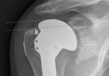
Nonoperative Treatment of Closed Extra-Articular Distal Humeral Shaft Fractures in Adults: A Comparison of Functional Bracing and Above-Elbow Casting
ABSTRACT
Diaphyseal fractures of the distal humerus have a high rate of union when treated with a functional brace or an above-elbow cast (AEC). This study compares alignment of the humerus and motion of the elbow after functional brace or AEC treatment.
One-hundred and five consecutive patients with a closed, extra-articular fracture of the distal humeral diaphysis were identified in the orthopedic trauma databases of 3 hospitals between 2003 and 2012. Seventy-five patients with a follow-up of at least 6 months or with radiographic and clinical evidence of fracture union were included (51 treated with functional bracing and 24 treated with an AEC).
All of the fractures healed. The average arc of elbow flexion was 130° ± 9° in braced patients vs 127° ± 12° in casted patients. Four patients (8%) in the bracing group and 4 (17%) in the casting group lost >20° of elbow motion. The average varus angulation on radiographs was 17° ± 8° in braced and 13° ± 8° in casted patients, while the average posterior angulation was 9° ± 6° vs 7° ± 7°, respectively.
Closed extra-articular distal diaphyseal humerus fractures heal with both bracing and casting and there are no differences in average elbow motion or radiographic alignment.
Nonoperative treatment of closed fractures of the humeral shaft (AO/OTA [Arbeitsgemeinschaft für Osteosynthesefragen/Orthopaedic Trauma Association] type 12) with a functional brace or above-elbow cast (AEC) is associated with a high union rate, good motion, and good function. Advocates of casting believe that a brace cannot control fracture alignment as well as a cast that allows for immobilization and molding. Advocates of brace treatment are concerned that immobilization in a cast will cause elbow stiffness.1-11
Continue to: In our differing institutions...
In our differing institutions, there are advocates of each type of treatment, providing the opportunity for a comparison. This retrospective study compares brace and cast treatment. The working hypothesis was that there is no difference in elbow motion 6 months or more after fracture. We also compared radiographic alignment after union.
MATERIALS AND METHODS
Between 2003 and 2012, consecutive adult patients treated for a nonpathological fracture of the diaphysis of the distal humerus at the orthopedic trauma service of 3 level 1 academic trauma centers were identified from prospectively collected trauma injury databases. Patients with vascular injury, ipsilateral upper extremity fracture, and periprosthetic fractures were excluded. The attending orthopedic surgeon chose the treatment method and evaluated the range of motion (ROM) of the elbow and radiographic union at the final ambulatory visit. We included patients followed to clinical and radiographic union with a minimum of 6 months of follow-up. We also included patients with <6 months’ follow-up who demonstrated union and had elbow ROM within 10° of the uninjured arm.
We identified 105 consecutive adult patients with a closed nonpathological extra-articular distal humeral shaft fracture (fracture of the distal humeral shaft with an AO/OTA type-12.A, 12.B, or 12.C pattern) treated with an AEC or a brace in our databases.12 Two patients in the brace group chose surgery to improve alignment within 3 weeks of injury and were excluded from the analysis. Twenty-eight patients had inadequate follow-up.
A total of 75 patients were included in the study. At the first and second institutions, 51 patients were treated with functional bracing with an average follow-up of 7 months. At the third institution, 24 patients were treated with an AEC with an average follow-up of 4 months. Seventeen out of 24 patients in the long arm casting group and 19 out of 51 patients in the bracing group, who were included since they had <6 months of follow-up, demonstrated union and had elbow ROM within 10° of the uninjured arm. Differing methods of closed immobilization were the result of differing treatment algorithms at each institution.
The patients who were treated with a functional brace averaged 34 years of age (range, 18-90 years) and included 27 men and 24 women. The brace was removed at an average of 11.5 weeks (range, 8-18 weeks) after initial injury. Six patients had an injury-associated radial nerve palsy, all of which fully recovered within an average of 4 months (range, 0.5-7 months). Sixteen patients were injured due to a fall from standing height, 2 due to a fall from a greater height than standing, 16 in a motor-vehicle accident, 15 during a sport activity, and 2 were not specifically documented.
Continue to: Four patients had concomitant...
Four patients had concomitant injuries: one patient had a mid-shaft humeral fracture on the contralateral arm; a second had an ankle fracture; a third had an ankle fracture, acetabular fracture, a rib fracture, and pneumothorax; and the fourth had 2 rib fractures.
The patients who were treated with an AEC had an average age of 32 years (range,18-82 years) and included 14 men and 10 women. The cast was removed at an average of 4.2 weeks (range, 3-7 weeks) after the initial injury. Two patients had an injury-associated radial nerve palsy, both of which fully recovered. Five patients were injured due to a fall from standing height, 1 due to a fall from a height greater than standing, 7 during a motor-vehicle accident, 5 during a sport activity, and 6 were not documented. Two patients sustained concomitant injuries: one patient sustained a tibia-fibula fracture, and another patient sustained facial trauma.
The 2 groups were comparable in age and gender, as well as the injury mechanism (Table).
Table. Patient Demographics and Outcome Data
| Functional Bracing (n = 51) | Long Arm Casting (n = 24) | Significance (P < .05) |
Sex |
|
|
|
Male | 27 (54%) | 14 (58%) |
|
Female | 24 (46%) | 10 (42%) |
|
Average age (y) | 34 (range, 18-90) | 32 (range, 18-82) |
|
Mechanism of injury |
|
|
|
Standing height | 16 (31%) | 5 (20%) |
|
Greater height | 2 (4%) | 1 (4%) |
|
Motor vehicle collision | 16 (31%) | 7 (29%) |
|
Sports activity | 15 (29 %) | 5 (21%) |
|
Other | 2 (4%) | 6 (25%) |
|
Follow-up (months) | 7 (range, 2-25) | 4 (range, 2-15) |
|
Elbow range of motion (degrees) | 130 ± 9.4 | 127 ± 11.9 | P = .26 |
Varus/valgus angulation (degrees) | 17 ± 7.8 varus | 13 ± 8.4 varus | P = .11 |
Anterior/posterior angulation (degrees) | 9 ± 6.2 posterior | 7 ± 7.5 posterior | P = .54 |
FUNCTIONAL BRACING TECHNIQUE
Upon presentation after injury, patients were immobilized in a coaptation splint (Figure 1A). Within 10 days, the arm was placed in a pre-manufactured polyethylene functional brace (Corflex) and the arm was supported with a simple sling. Patients were allowed to use the hand for light tasks and move the elbow, but most patients were not capable of active elbow flexion exercises until early healing was established 4 to 6 weeks after injury. Shoulder motion was discouraged until radiographic union. Patients started active, self-assisted elbow and shoulder stretching exercises, and weaned from the brace once radiographic union was confirmed between 6 and 10 weeks after injury (Figures 1B, 1C). 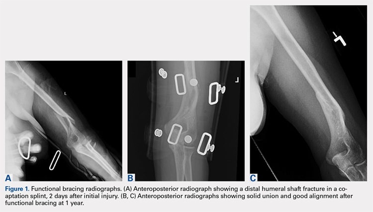
ABOVE-ELBOW CASE
Patients were also initially immobilized in a coaptation splint upon initial presentation. Within 7 days, an above-elbow fiberglass cast with neutral forearm rotation and 90° of elbow flexion was applied with a supracondylar mold, followed by radiographic imaging (Figure 2A). With the fractured arm dependent, a valgus mold was applied as the material hardened in order to align the fracture site and limit varus angulation.
Continue to: There were no shoulder...
There were no shoulder ROM restrictions. Casts were removed, skin checked, and replaced every week for 4 to 6 weeks. Casts were removed when callus was noted on radiographs. After cast removal, physician-taught active and active-assisted elbow stretching exercises were given to patients to be performed on a daily basis at home. Patients were followed until clinical and radiographic union and elbow ROM to within 10° of the injured arm (Figures 2B, 2C).
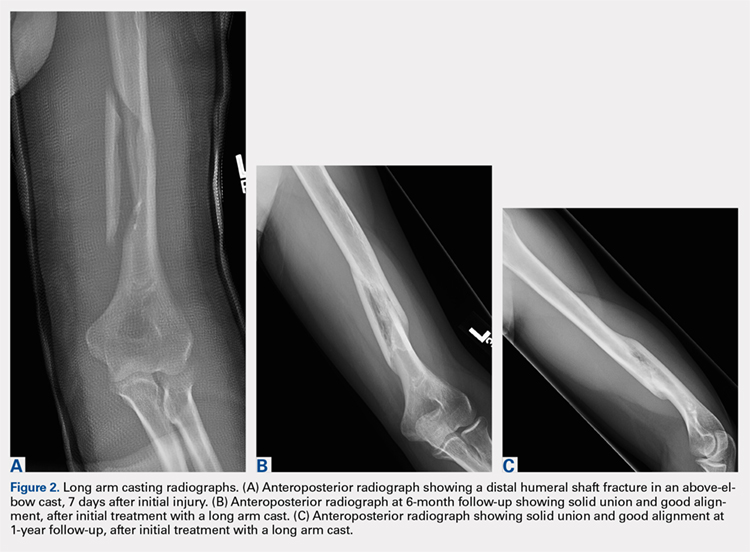
STATISTICAL ANALYSIS
Alignment of the humerus (including varus-valgus alignment and apex anterior-posterior alignment) was measured on anteroposterior and lateral radiographs as the angle between lines bisecting the humeral diaphysis proximal and distal to the fracture. The normality of the data was tested using the Kolmogorov-Smirnov test. To statistically compare continuous variables with a normal distribution, t-tests were used; otherwise the Wilcoxon t-test was applied. The Pearson’s Chi-Square test was used to statistically compare dichotomous variables, except when expected cell frequency was <5, in which case the Fisher exact test was used. The level of significance was set at P < .05.
RESULTS
RANGE OF MOTION AND RADIOGRAPHIC ALIGNMENT
The average range of elbow motion was 130° ± 9° after brace treatment and 127° ± 12° after cast treatment (P = .26). Four patients (8%) treated with a brace and 3 (12%) treated with a cast lost >20° of elbow motion.
All the fractures healed. The average varus angulation on the anteroposterior radiograph was 17° (range, 2°-26°) in braced patients and 13 (range, 5°-31°) in casted patients (P = .11). The average posterior angulation on the lateral radiograph was 9° (range, 0°-28°) in braced patients vs 7° (range, 2°-33°) in casted patients (P = .54).
Continue to: Two weeks after initiating brace...
COMPLICATIONS
Two weeks after initiating brace treatment, an obese patient suffered a rash with desquamation that necessitated discontinuation of the brace. However, the skin and fracture ultimately healed with a coaptation splint and sling support without additional complications. In the casting cohort, 2 patients returned to the emergency department after AEC placement because of swelling of the hand and pain in the cast. Both casts were removed and reapplied.
DISCUSSION
Fractures of the distal third of the humeral diaphysis heal without surgery. Fracture angulation and elbow stiffness are the concerns that lead to variations in nonoperative treatment.1-3 Advocates of casting believe they can get better alignment without losing elbow motion, and advocates of bracing feel that the brace is less cumbersome.1-3,5-8 We compared these treatments retrospectively and found them comparable.
This study should be considered in light of its limitations. Many patients were lost to follow-up in our urban trauma centers. We do not know if these patients did better, worse, or the same as the patients we were able to evaluate, but our opinion is that patients having problems were more likely to return. The evaluation time was relatively short, but motion can only improve in the longer-term. Two patients that were initially braced chose surgery, probably because either they or their surgeon were nervous about the radiographic appearance of the fracture. In our opinion, continued nonoperative treatment of these patients would not affect the findings.
Cast treatment of distal diaphyseal humerus fractures does not cause permanent elbow stiffness. This is confirmed by our results; as casted patients did not lose final ROM compared to the bracing cohort. These injuries are extra-articular and casted patients are transitioned to bracing once humeri have significant union demonstrated by the arm moving as a unit. To our knowledge, there is no other study that has evaluated casting for these fractures, but it may be that evidence of permanent stiffness with nonoperative treatment of distal metaphyseal fractures of the humerus [AO/OTA type 13] is misapplied to distal humeral shaft fractures [AO/OTA type 12].3,9,10,12 For brace treatment, Sarmiento and colleagues9 showed no significant elbow stiffness in a consecutive cohort of 69 patients, while Jawa and colleagues5 showed no increased elbow stiffness compared to plate fixation. Given the accumulated data,3,5,6,8,13 advocates of operative treatment for distal third diaphyseal humerus fractures12 can no longer site elbow stiffness as a disadvantage of nonoperative treatment, whether with cast or brace.
As shown in this study, patients that choose nonoperative treatment can expect their fracture to heal with an average of approximately 15° of varus angulation, as well as 2 others evaluating brace treatment.5,9 Some will heal with as much as 30° of varus angulation.5,9 The arm may look a little different, particularly in thin patients, but there is no evidence that this angulation affects function. The risks, discomforts, and inconveniences of surgery can be balanced with the ability of surgery to improve alignment and allow elbow motion a few weeks earlier. The aesthetics of the scar after surgery may not be better than the deformity after nonoperative treatment. Patients should be involved in these decisions.
Continue to: No cost comparison...
No cost comparison was done between these 2 treatment modalities. However, both casting and bracing offer substantially lower costs comparted to surgical treatment with high efficacy and less risk for the patient. In some billing environments, closed treatments of fractures are captured as “surgical interventions” with global periods included in the reimbursement. Both casting and bracing are relatively inexpensive with materials that are readily accessible in nearly any general or subspecialty orthopedic practice.
There is a passive implication that operative treatment of distal third diaphyseal humerus fractures affords better results and union for patients in the discussed literature. Our results demonstrate that the distal diaphyseal humerus has a natural anatomic and biologic propensity to heal with closed immobilization. Patients should be made aware that while operative treatments exist for this fracture pattern, nonoperative treatment modalities have proven to be efficacious using a variety of immobilization methods. Thus, patients that prefer nonoperative treatment of a distal third diaphyseal humerus fracture can choose between a cast or a brace with confidence of the efficacy of the nonoperative treatment.
1. McKee MD. Fractures of the shaft of the humerus. In: Bucholz R, Heckman JD, Court-Brown C, eds. Rockwood and Green’s Fractures in Adults. 6th ed. Philadelphia: Lippencott Williams & Wilkins; 2006:1117-1159.
2. Schemitsch E, Bhandari M, Talbot M. Fractures of the humeral shaft. In: Browner BD, Jupiter JB, Levine AM, Trafton PG, Krettek C, eds. Skeletal Trauma. 4th ed. Philadelphia: Saunders-Elsevier Company; 2009:1593-1622.
3. Walker M, Palumbo B, Badman B, Brooks J, Van Gelderen J, Mighell M. Humeral shaft fractures: a review. J Shoulder Elbow Surg. 2011;20(5):833-844. doi:10.1016/j.jse.2010.11.030.
4. Balfour GW, Mooney V, Ashby ME. Diaphyseal fractures of the humerus treated with a ready-made fracture brace. J Bone Joint Surg Am. 1982;64(1):11-13. doi:10.2106/00004623-198264010-00002.
5. Jawa A, McCarty P, Doornberg J, Harris M, Ring D. Extra-articular distal-third diaphyseal fractures of the humerus. A comparison of functional bracing and plate fixation. J Bone Joint Surg Am. 2006;88(11):2343-2347. doi:10.2106/JBJS.F.00334.
6. Pehlivan O. Functional treatment of the distal third humeral shaft fractures. Arch Orthop Trauma Surg. 2002;122(7):390-395. doi:10.1007/s00402-002-0403-x.
7. Ring D, Chin K, Taghinia AH, Jupiter JB. Nonunion after functional brace treatment of diaphyseal humerus fractures. J Trauma. 2007;62(5):1157-1158. doi:10.1097/01.ta.0000222719.52619.2c.
8. Sarmiento A, Horowitch A, Aboulafia A, Vangsness CT Jr. Functional bracing for comminuted extra-articular fractures of the distal third of the humerus. J Bone Joint Surg Br. 1990;72(4):283-287.
9. Sarmiento A, Kinman PB, Galvin EG, Schmitt RH, Phillips JG. Functional bracing of fractures of the shaft of the humerus. J Bone Joint Surg Am. 1977;59(5):596-601.
10. Toivanen JA, Nieminen J, Laine HJ, Honkonen SE, Jarvinen MJ. Functional treatment of closed humeral shaft fractures. Int Orthop. 2005;29(1):10-13. doi:10.1007/s00264-004-0612-8.
11. Wallny T, Westermann K, Sagebiel C, Reimer M, Wagner UA. Functional treatment of humeral shaft fractures: indications and results. J Orthop Trauma. 1997;11(4):283-287.
12. Marsh JL, Slongo TF, Agel J, et al. Fracture and dislocation classification compendium - 2007: Orthopaedic Trauma Association classification, database and outcomes committee. J Orthop Trauma. 2007;21(10 Suppl):S1-S133.
13. Paris H, Tropiano P, Clouet D'orval B, Chaudet H, Poitout DG. Fractures of the shaft of the humerus: systematic plate fixation. Anatomic and functional results in 156 cases and a review of the literature. Rev Chir Orthop Reparatrice Appar Mot. 2000;86(4):346-359.
ABSTRACT
Diaphyseal fractures of the distal humerus have a high rate of union when treated with a functional brace or an above-elbow cast (AEC). This study compares alignment of the humerus and motion of the elbow after functional brace or AEC treatment.
One-hundred and five consecutive patients with a closed, extra-articular fracture of the distal humeral diaphysis were identified in the orthopedic trauma databases of 3 hospitals between 2003 and 2012. Seventy-five patients with a follow-up of at least 6 months or with radiographic and clinical evidence of fracture union were included (51 treated with functional bracing and 24 treated with an AEC).
All of the fractures healed. The average arc of elbow flexion was 130° ± 9° in braced patients vs 127° ± 12° in casted patients. Four patients (8%) in the bracing group and 4 (17%) in the casting group lost >20° of elbow motion. The average varus angulation on radiographs was 17° ± 8° in braced and 13° ± 8° in casted patients, while the average posterior angulation was 9° ± 6° vs 7° ± 7°, respectively.
Closed extra-articular distal diaphyseal humerus fractures heal with both bracing and casting and there are no differences in average elbow motion or radiographic alignment.
Nonoperative treatment of closed fractures of the humeral shaft (AO/OTA [Arbeitsgemeinschaft für Osteosynthesefragen/Orthopaedic Trauma Association] type 12) with a functional brace or above-elbow cast (AEC) is associated with a high union rate, good motion, and good function. Advocates of casting believe that a brace cannot control fracture alignment as well as a cast that allows for immobilization and molding. Advocates of brace treatment are concerned that immobilization in a cast will cause elbow stiffness.1-11
Continue to: In our differing institutions...
In our differing institutions, there are advocates of each type of treatment, providing the opportunity for a comparison. This retrospective study compares brace and cast treatment. The working hypothesis was that there is no difference in elbow motion 6 months or more after fracture. We also compared radiographic alignment after union.
MATERIALS AND METHODS
Between 2003 and 2012, consecutive adult patients treated for a nonpathological fracture of the diaphysis of the distal humerus at the orthopedic trauma service of 3 level 1 academic trauma centers were identified from prospectively collected trauma injury databases. Patients with vascular injury, ipsilateral upper extremity fracture, and periprosthetic fractures were excluded. The attending orthopedic surgeon chose the treatment method and evaluated the range of motion (ROM) of the elbow and radiographic union at the final ambulatory visit. We included patients followed to clinical and radiographic union with a minimum of 6 months of follow-up. We also included patients with <6 months’ follow-up who demonstrated union and had elbow ROM within 10° of the uninjured arm.
We identified 105 consecutive adult patients with a closed nonpathological extra-articular distal humeral shaft fracture (fracture of the distal humeral shaft with an AO/OTA type-12.A, 12.B, or 12.C pattern) treated with an AEC or a brace in our databases.12 Two patients in the brace group chose surgery to improve alignment within 3 weeks of injury and were excluded from the analysis. Twenty-eight patients had inadequate follow-up.
A total of 75 patients were included in the study. At the first and second institutions, 51 patients were treated with functional bracing with an average follow-up of 7 months. At the third institution, 24 patients were treated with an AEC with an average follow-up of 4 months. Seventeen out of 24 patients in the long arm casting group and 19 out of 51 patients in the bracing group, who were included since they had <6 months of follow-up, demonstrated union and had elbow ROM within 10° of the uninjured arm. Differing methods of closed immobilization were the result of differing treatment algorithms at each institution.
The patients who were treated with a functional brace averaged 34 years of age (range, 18-90 years) and included 27 men and 24 women. The brace was removed at an average of 11.5 weeks (range, 8-18 weeks) after initial injury. Six patients had an injury-associated radial nerve palsy, all of which fully recovered within an average of 4 months (range, 0.5-7 months). Sixteen patients were injured due to a fall from standing height, 2 due to a fall from a greater height than standing, 16 in a motor-vehicle accident, 15 during a sport activity, and 2 were not specifically documented.
Continue to: Four patients had concomitant...
Four patients had concomitant injuries: one patient had a mid-shaft humeral fracture on the contralateral arm; a second had an ankle fracture; a third had an ankle fracture, acetabular fracture, a rib fracture, and pneumothorax; and the fourth had 2 rib fractures.
The patients who were treated with an AEC had an average age of 32 years (range,18-82 years) and included 14 men and 10 women. The cast was removed at an average of 4.2 weeks (range, 3-7 weeks) after the initial injury. Two patients had an injury-associated radial nerve palsy, both of which fully recovered. Five patients were injured due to a fall from standing height, 1 due to a fall from a height greater than standing, 7 during a motor-vehicle accident, 5 during a sport activity, and 6 were not documented. Two patients sustained concomitant injuries: one patient sustained a tibia-fibula fracture, and another patient sustained facial trauma.
The 2 groups were comparable in age and gender, as well as the injury mechanism (Table).
Table. Patient Demographics and Outcome Data
| Functional Bracing (n = 51) | Long Arm Casting (n = 24) | Significance (P < .05) |
Sex |
|
|
|
Male | 27 (54%) | 14 (58%) |
|
Female | 24 (46%) | 10 (42%) |
|
Average age (y) | 34 (range, 18-90) | 32 (range, 18-82) |
|
Mechanism of injury |
|
|
|
Standing height | 16 (31%) | 5 (20%) |
|
Greater height | 2 (4%) | 1 (4%) |
|
Motor vehicle collision | 16 (31%) | 7 (29%) |
|
Sports activity | 15 (29 %) | 5 (21%) |
|
Other | 2 (4%) | 6 (25%) |
|
Follow-up (months) | 7 (range, 2-25) | 4 (range, 2-15) |
|
Elbow range of motion (degrees) | 130 ± 9.4 | 127 ± 11.9 | P = .26 |
Varus/valgus angulation (degrees) | 17 ± 7.8 varus | 13 ± 8.4 varus | P = .11 |
Anterior/posterior angulation (degrees) | 9 ± 6.2 posterior | 7 ± 7.5 posterior | P = .54 |
FUNCTIONAL BRACING TECHNIQUE
Upon presentation after injury, patients were immobilized in a coaptation splint (Figure 1A). Within 10 days, the arm was placed in a pre-manufactured polyethylene functional brace (Corflex) and the arm was supported with a simple sling. Patients were allowed to use the hand for light tasks and move the elbow, but most patients were not capable of active elbow flexion exercises until early healing was established 4 to 6 weeks after injury. Shoulder motion was discouraged until radiographic union. Patients started active, self-assisted elbow and shoulder stretching exercises, and weaned from the brace once radiographic union was confirmed between 6 and 10 weeks after injury (Figures 1B, 1C).
ABOVE-ELBOW CASE
Patients were also initially immobilized in a coaptation splint upon initial presentation. Within 7 days, an above-elbow fiberglass cast with neutral forearm rotation and 90° of elbow flexion was applied with a supracondylar mold, followed by radiographic imaging (Figure 2A). With the fractured arm dependent, a valgus mold was applied as the material hardened in order to align the fracture site and limit varus angulation.
Continue to: There were no shoulder...
There were no shoulder ROM restrictions. Casts were removed, skin checked, and replaced every week for 4 to 6 weeks. Casts were removed when callus was noted on radiographs. After cast removal, physician-taught active and active-assisted elbow stretching exercises were given to patients to be performed on a daily basis at home. Patients were followed until clinical and radiographic union and elbow ROM to within 10° of the injured arm (Figures 2B, 2C).
STATISTICAL ANALYSIS
Alignment of the humerus (including varus-valgus alignment and apex anterior-posterior alignment) was measured on anteroposterior and lateral radiographs as the angle between lines bisecting the humeral diaphysis proximal and distal to the fracture. The normality of the data was tested using the Kolmogorov-Smirnov test. To statistically compare continuous variables with a normal distribution, t-tests were used; otherwise the Wilcoxon t-test was applied. The Pearson’s Chi-Square test was used to statistically compare dichotomous variables, except when expected cell frequency was <5, in which case the Fisher exact test was used. The level of significance was set at P < .05.
RESULTS
RANGE OF MOTION AND RADIOGRAPHIC ALIGNMENT
The average range of elbow motion was 130° ± 9° after brace treatment and 127° ± 12° after cast treatment (P = .26). Four patients (8%) treated with a brace and 3 (12%) treated with a cast lost >20° of elbow motion.
All the fractures healed. The average varus angulation on the anteroposterior radiograph was 17° (range, 2°-26°) in braced patients and 13 (range, 5°-31°) in casted patients (P = .11). The average posterior angulation on the lateral radiograph was 9° (range, 0°-28°) in braced patients vs 7° (range, 2°-33°) in casted patients (P = .54).
Continue to: Two weeks after initiating brace...
COMPLICATIONS
Two weeks after initiating brace treatment, an obese patient suffered a rash with desquamation that necessitated discontinuation of the brace. However, the skin and fracture ultimately healed with a coaptation splint and sling support without additional complications. In the casting cohort, 2 patients returned to the emergency department after AEC placement because of swelling of the hand and pain in the cast. Both casts were removed and reapplied.
DISCUSSION
Fractures of the distal third of the humeral diaphysis heal without surgery. Fracture angulation and elbow stiffness are the concerns that lead to variations in nonoperative treatment.1-3 Advocates of casting believe they can get better alignment without losing elbow motion, and advocates of bracing feel that the brace is less cumbersome.1-3,5-8 We compared these treatments retrospectively and found them comparable.
This study should be considered in light of its limitations. Many patients were lost to follow-up in our urban trauma centers. We do not know if these patients did better, worse, or the same as the patients we were able to evaluate, but our opinion is that patients having problems were more likely to return. The evaluation time was relatively short, but motion can only improve in the longer-term. Two patients that were initially braced chose surgery, probably because either they or their surgeon were nervous about the radiographic appearance of the fracture. In our opinion, continued nonoperative treatment of these patients would not affect the findings.
Cast treatment of distal diaphyseal humerus fractures does not cause permanent elbow stiffness. This is confirmed by our results; as casted patients did not lose final ROM compared to the bracing cohort. These injuries are extra-articular and casted patients are transitioned to bracing once humeri have significant union demonstrated by the arm moving as a unit. To our knowledge, there is no other study that has evaluated casting for these fractures, but it may be that evidence of permanent stiffness with nonoperative treatment of distal metaphyseal fractures of the humerus [AO/OTA type 13] is misapplied to distal humeral shaft fractures [AO/OTA type 12].3,9,10,12 For brace treatment, Sarmiento and colleagues9 showed no significant elbow stiffness in a consecutive cohort of 69 patients, while Jawa and colleagues5 showed no increased elbow stiffness compared to plate fixation. Given the accumulated data,3,5,6,8,13 advocates of operative treatment for distal third diaphyseal humerus fractures12 can no longer site elbow stiffness as a disadvantage of nonoperative treatment, whether with cast or brace.
As shown in this study, patients that choose nonoperative treatment can expect their fracture to heal with an average of approximately 15° of varus angulation, as well as 2 others evaluating brace treatment.5,9 Some will heal with as much as 30° of varus angulation.5,9 The arm may look a little different, particularly in thin patients, but there is no evidence that this angulation affects function. The risks, discomforts, and inconveniences of surgery can be balanced with the ability of surgery to improve alignment and allow elbow motion a few weeks earlier. The aesthetics of the scar after surgery may not be better than the deformity after nonoperative treatment. Patients should be involved in these decisions.
Continue to: No cost comparison...
No cost comparison was done between these 2 treatment modalities. However, both casting and bracing offer substantially lower costs comparted to surgical treatment with high efficacy and less risk for the patient. In some billing environments, closed treatments of fractures are captured as “surgical interventions” with global periods included in the reimbursement. Both casting and bracing are relatively inexpensive with materials that are readily accessible in nearly any general or subspecialty orthopedic practice.
There is a passive implication that operative treatment of distal third diaphyseal humerus fractures affords better results and union for patients in the discussed literature. Our results demonstrate that the distal diaphyseal humerus has a natural anatomic and biologic propensity to heal with closed immobilization. Patients should be made aware that while operative treatments exist for this fracture pattern, nonoperative treatment modalities have proven to be efficacious using a variety of immobilization methods. Thus, patients that prefer nonoperative treatment of a distal third diaphyseal humerus fracture can choose between a cast or a brace with confidence of the efficacy of the nonoperative treatment.
1. McKee MD. Fractures of the shaft of the humerus. In: Bucholz R, Heckman JD, Court-Brown C, eds. Rockwood and Green’s Fractures in Adults. 6th ed. Philadelphia: Lippencott Williams & Wilkins; 2006:1117-1159.
2. Schemitsch E, Bhandari M, Talbot M. Fractures of the humeral shaft. In: Browner BD, Jupiter JB, Levine AM, Trafton PG, Krettek C, eds. Skeletal Trauma. 4th ed. Philadelphia: Saunders-Elsevier Company; 2009:1593-1622.
3. Walker M, Palumbo B, Badman B, Brooks J, Van Gelderen J, Mighell M. Humeral shaft fractures: a review. J Shoulder Elbow Surg. 2011;20(5):833-844. doi:10.1016/j.jse.2010.11.030.
4. Balfour GW, Mooney V, Ashby ME. Diaphyseal fractures of the humerus treated with a ready-made fracture brace. J Bone Joint Surg Am. 1982;64(1):11-13. doi:10.2106/00004623-198264010-00002.
5. Jawa A, McCarty P, Doornberg J, Harris M, Ring D. Extra-articular distal-third diaphyseal fractures of the humerus. A comparison of functional bracing and plate fixation. J Bone Joint Surg Am. 2006;88(11):2343-2347. doi:10.2106/JBJS.F.00334.
6. Pehlivan O. Functional treatment of the distal third humeral shaft fractures. Arch Orthop Trauma Surg. 2002;122(7):390-395. doi:10.1007/s00402-002-0403-x.
7. Ring D, Chin K, Taghinia AH, Jupiter JB. Nonunion after functional brace treatment of diaphyseal humerus fractures. J Trauma. 2007;62(5):1157-1158. doi:10.1097/01.ta.0000222719.52619.2c.
8. Sarmiento A, Horowitch A, Aboulafia A, Vangsness CT Jr. Functional bracing for comminuted extra-articular fractures of the distal third of the humerus. J Bone Joint Surg Br. 1990;72(4):283-287.
9. Sarmiento A, Kinman PB, Galvin EG, Schmitt RH, Phillips JG. Functional bracing of fractures of the shaft of the humerus. J Bone Joint Surg Am. 1977;59(5):596-601.
10. Toivanen JA, Nieminen J, Laine HJ, Honkonen SE, Jarvinen MJ. Functional treatment of closed humeral shaft fractures. Int Orthop. 2005;29(1):10-13. doi:10.1007/s00264-004-0612-8.
11. Wallny T, Westermann K, Sagebiel C, Reimer M, Wagner UA. Functional treatment of humeral shaft fractures: indications and results. J Orthop Trauma. 1997;11(4):283-287.
12. Marsh JL, Slongo TF, Agel J, et al. Fracture and dislocation classification compendium - 2007: Orthopaedic Trauma Association classification, database and outcomes committee. J Orthop Trauma. 2007;21(10 Suppl):S1-S133.
13. Paris H, Tropiano P, Clouet D'orval B, Chaudet H, Poitout DG. Fractures of the shaft of the humerus: systematic plate fixation. Anatomic and functional results in 156 cases and a review of the literature. Rev Chir Orthop Reparatrice Appar Mot. 2000;86(4):346-359.
TAKE-HOME POINTS
- Closed extra-articular distal diaphyseal humerus fractures heal predictably with both bracing and casting.
- There are no differences in average elbow motion between bracing and casting of these fractures.
- There are no differences in radiographic alignment between bracing and casting of these fractures.
- The distal diaphyseal humerus has a natural anatomic and biologic propensity to heal with closed immobilization.
- Patients preferring nonoperative treatment can choose between a cast or a brace with confidence of the efficacy of either treatment.
Proximal Humerus Fracture 3-D Modeling
ABSTRACT
The objective of this study is to determine the reproducibility and feasibility of using 3-dimensional (3-D) computer simulation of proximal humerus fracture computed tomography (CT) scans for fracture reduction. We hypothesized that anatomic reconstruction with 3-D models would be anatomically accurate and reproducible.
Preoperative CT scans of 28 patients with 3- and 4-part (AO classification 11-B1, 11-B2, 11-C1, 11-C2) proximal humerus fractures who were treated by hemiarthroplasty were converted into 3-D computer models. The displaced fractured fragments were anatomically reduced with computer simulation by 2 fellowship-trained shoulder surgeons, and measurements were made of the reconstructed proximal humerus.
The measurements of the reconstructed models had very good to excellent interobserver and intraobserver reliability. The reconstructions of these humerus fractures showed interclass correlation coefficients ranging from 0.71 to 0.93 between 1 observer and from 0.82 to 0.98 between 2 different observers. The fracture reduction was judged against normal proximal humerus geometry to determine reduction accuracy.
The 3-D modeling techniques used to reconstruct 3- and 4-part proximal humerus fractures were reliable and accurate. This technique of modeling and reconstructing proximal humerus fractures could be used to enhance the preoperative planning of open reduction and internal fixation or hemiarthroplasty for 3- and 4-part proximal humerus fractures.
The treatment of proximal humerus fractures is influenced by multiple factors, including patient age, associated injuries, bone quality, and fracture pattern. Three- and 4-part fractures are among the more severe of these fractures, which may result in vascular compromise to the humeral head, leading to avascular necrosis. Surgical goals for the management of these fractures are to optimize functional outcomes by re-creating a stable construct with a functional rotator cuff by open reduction and internal fixation (ORIF), hemiarthroplasty with tuberosity ORIF, or reverse shoulder replacement. Achieving a good outcome following hemiarthroplasty is dependent on many factors, including anatomic tuberosity healing and component positioning.1,2,3 Repairing the greater tuberosity in a near-anatomic position has been shown to greatly affect the results of hemiarthroplasty for fracture.3,4
Continue to: Three-dimensional (3-D) modeling...
Three-dimensional (3-D) modeling is increasingly being used in preoperative planning of shoulder arthroplasty and determining proper proximal humeral fracture treatment. 5 However, no studies have examined the reconstruction of a fractured proximal humerus into native anatomy using computer simulation. The purpose of this study is to determine the accuracy and reliability of anatomically reconstructing the preinjury proximal humerus using 3-D computer models created from postinjury computed tomography (CT) scans. The results of this study could lead to useful techniques employing CT–based models for patient-specific preoperative planning of proximal humeral fracture ORIF and during tuberosity reduction and fixation during hemiarthroplasty for fracture. We hypothesize that it is feasible to reconstruct the original anatomy of the proximal humerus by using 3-D computer modeling of proximal humerus fractures with high reliability based on interobserver and intraobserver review.
METHODS
After Institutional Review Board approval was obtained, we reviewed the medical records of consecutive patients with a diagnosis of proximal humeral fracture and the treatment codes for hemiarthroplasty from 2000 to 2013. Inclusion criteria included 3- and 4-part fractures (AO classifications 11-B1, 11-B2, 11-C1, 11-C2). CT scans with insufficient quality to differentiate bone from soft tissue (inadequate signal-to-noise ratio) were excluded from the study. A total of 28 patients with adequate CT scans met the criteria for inclusion in this study.
The CT scan protocol included 0.5-mm axial cuts with inclusion of the proximal humerus in the Digital Imaging and Communications in Medicine format. These CT scans were converted into patient-specific 3-D computer models of the shoulder using Mimics software (Materialise Inc.). The use of this software to produce anatomically accurate models has previously been verified in a shoulder model.6,7 The tuberosity fragments were then individually separated from each other using the voxel-selecting capabilities of 3-D software and manipulated with translation and rotation for anatomic reduction (Figures 1A-1D, Figure 2). 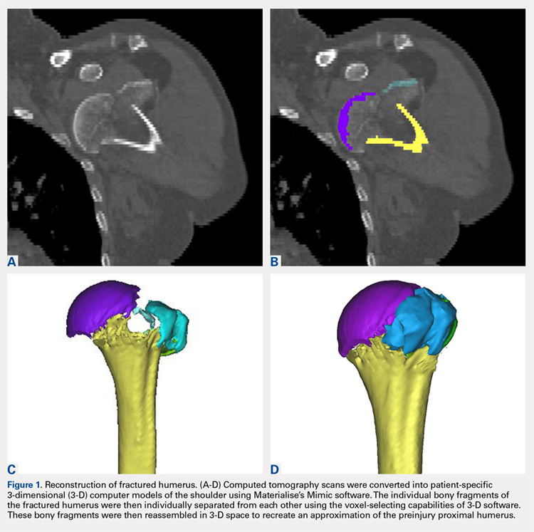
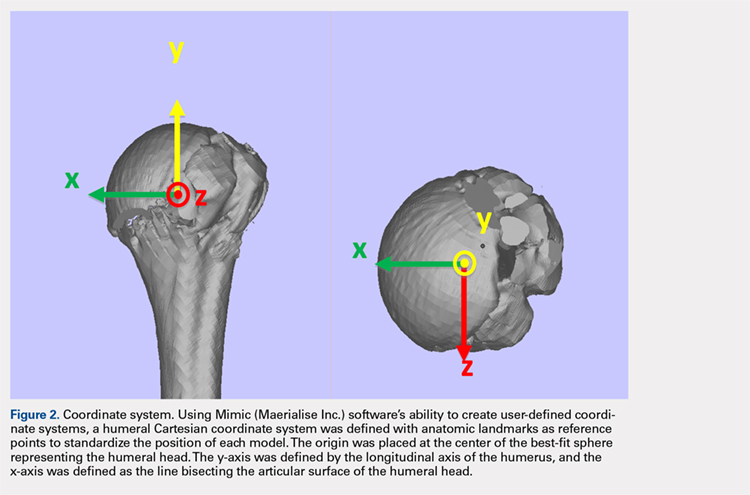
The de-identified anatomically reconstructed shoulder models were then uploaded into Materialise’s Magics rapid prototyping software, and a user-defined humeral Cartesian coordinate system was defined with anatomic landmarks as reference points to standardize the position of each model (Figure 3).8,9 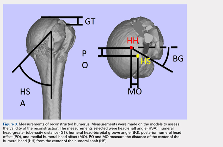
A series of measurements were made on these models to assess the validity and reliability of the reassembly. The bicipital groove at the anatomic neck was used to measure humeral head version as described by Kummer and colleagues.10 The head-shaft angle, humeral head-greater tuberosity distance, humeral head-bicipital groove angle, and posterior and medial humeral head offset were measured directly on the reconstructed humerus.
Continue to: Two fellowship-trained shoulder...
Two fellowship-trained shoulder surgeons independently reassembled these fracture fragments via computer simulation. Interobserver reliability testing was conducted on these reconstructions by measuring the geometry between the 2 different surgeons’ reconstructions. Intraobserver reliability testing was conducted by 1 surgeon repeating the reconstructions with 4-week intervals between trials and measuring the geometry between the 2 different trials. The average dimensions of the reconstructed proximal humerus fractures were compared with the geometry of normal humeri reported in previously conducted anatomic studies.11,12,13
STATISTICS
The measured dimensions of the 28 reassembled proximal humeri models were averaged across all trials between the 2 fellowship-trained surgeons and compared with the range of normal dimensions of a healthy proximal humerus using the 2 one-sided tests (TOST) method for equivalence between 2 means given a range. The interobserver and intraobserver reliabilities were quantified using the interclass correlation coefficient. An excellent correlation was defined as a correlation coefficient >0.81; very good was defined as 0.61 to 0.80; and good was defined as 0.41 to 0.60.
RESULTS
Of the patients studied, 9 (32.1%) were male, and the average age at the time of CT scanning was 72 years. Of the 28 patients with fracture, 18 (64.2%) had 3-part fractures (AO classifications 11-B1, 11-B2), and 10 (35.8%) had 4-part fractures (AO classifications 11-C1, 11-C2). When examining the location of the intertubercular fracture line, we found that 13 (46.4%) fractures went through the bicipital groove. Of the remaining fracture lines, 9 (32.1%) extended into the greater tuberosity and 6 (21.4%) extended into the lesser tuberosity.
All users were able to reconstruct all 28 fractures using this technique. The average measured dimensions fell within the range of dimensions of a normal healthy proximal humerus specified in the literature to within a 95% confidence interval using the TOST for equivalence, in which we compared measured values with ranges reported in the literature (Table).11,12,13
Table. Dimensions of Proximal Humerus Geometry
| Normal Parameters | Average Dimensions From Trials | Dimensions From Literature |
| Head shaft angle | 43.5° ± 1° | 42.5° ± 12.5° |
| Head to greater tuberosity distance | 4.9 mm ± 0.4 mm | 8 mm ± 3.2 mm |
Head to bicipital groove angle (anatomic neck) | 26.4° ± 2° | 27.3° ± 14° |
| Posterior humeral head offset | 1.6 mm ± 0.3 mm | 4 mm ± 6 mm |
| Medial humeral head offset | 4.5 mm ± 0.3 mm | 9 mm ± 5 mm |
The reconstructions of these humerus fractures showed intraclass correlation coefficients ranging from 0.71 to 0.93 in 1 observer and interclass correlation coefficients from 0.82 to 0.98 between 2 different observers (Table).
DISCUSSION
This study demonstrates that it is feasible to reliably and accurately reconstruct the original anatomy of the proximal humerus by using 3-D computer modeling of proximal humerus fractures. Poor outcomes after hemiarthroplasty for proximal humerus fractures are mostly related to tuberosity malpositioning, resorption, or failure of fixation and resultant dysfunction of the rotator cuff.14,15,16 These studies highlight the importance of accurate tuberosity reduction during surgical care of these fractures.
Continue to: The 3-D computer model...
The 3-D computer model reconstruction of 3- and 4-part proximal humerus fractures were reliable and valid. The interclass correlation coefficients showed very good to excellent interobserver and intraobserver reliability for all measurements conducted. The averaged dimensions from all trials fell within the appropriate range of dimensions for a normal healthy humerus reported in the literature, as verified by the TOST method.11,12,13 The 3-D modeling capabilities demonstrated in this study allowed a greater understanding of the fracture patterns present in 3- and 4-part (AO classifications 11-B1, 11-B2, 11-C1, 11-C2) humerus fractures.
Overreduction of greater tuberosity to create cortical overlap with the lateral shaft may be used to promote bony union. As a result of this distalization, there may be extra strains placed on the rotator cuff, making the patient more prone to rotator cuff tear, as well as improperly balancing the dynamic stabilizers of the shoulder. Poor clinical outcomes in hemiarthroplasty for proximal humerus fractures have been correlated with a greater tuberosity placed distal relative to the humeral head by 1 cm in a study2 and by 2 cm in another.3
This study has several limitations. The first is the assumption that our injured patients had preinjury proximal humerus geometry within the range of normal dimensions of a healthy humerus. Unfortunately, because we were unable to obtain CT scans of the contralateral shoulder, we had to use standard proximal humerus geometry as the control. Another limitation, inherent in the technique, is that only cortical and dense trabecular bone was modeled, so that comminuted or osteoporotic bone was not well modeled. This study did not correlate the findings from these models with clinical outcomes. A prospective study is needed to evaluate the impact of this 3-D modeling on fracture reductions and clinical outcomes.
This study demonstrates that patient-specific modeling of proximal humerus fracture 3-D CT scans may help surgeons reliably and accurately reconstruct fractures. This technique may have utility in the preoperative planning of tuberosity fracture reduction and hemiarthroplasty. It gives surgeons the ability to visualize fracture fragments, and the process of reconstructing the fragments may help surgeons understand the required maneuvers for reduction at the time of surgery. This technique also provides dimensions of the patient’s native humerus, thus potentially improving the anatomic accuracy of the reduction or hemiarthroplasty reconstruction. With the new trend toward patient-specific instrumentation, this study also provides a means of planning the size of the humeral prostheses as well as the version relative to the biceps groove and intertubercular fracture line.
CONCLUSION
This study demonstrates the feasibility of using 3-D computer modeling of complex proximal humerus fractures in anatomic reconstruction. These techniques of computer-simulated 3-D models are valid and reliable. We believe that this technique of modeling and reconstructing proximal humerus fractures could be used to enhance the preoperative planning of hemiarthroplasty for 3- and 4-part proximal humerus fractures by providing improved understanding of the patient’s native humeral geometry and tuberosity reduction.
1. Boileau P, Krishnan SG, Tinsi L, Walch G, Coste JS, Mole D. Tuberosity malposition and migration: reasons for poor outcomes after hemiarthroplasty for displaced fractures of the proximal humerus. J Shoulder Elbow Surg. 2002;11(5):401-412. doi:10.1067/mse.2002.124527.
2. Mighell MA, Kolm GP, Collinge CA, Frankle MA. Outcomes of hemiarthroplasty for fractures of the proximal humerus. J Shoulder Elbow Surg. 2003;12(6):569-577. doi:10.1016/S1058274603002131.
3. Greiner SH, Kaab MJ, Kroning I, Scheibel M, Perka C. Reconstruction of humeral length and centering of the prosthetic head in hemiarthroplasty for proximal humeral fractures. J Shoulder Elbow Surg. 2008;17(5):709-714. doi:10.1016/j.jse.2008.03.004.
4. Smith AM, Mardones RM, Sperling JW, Cofield RH. Early complications of operatively treated proximal humeral fractures. J Shoulder Elbow Surg. 2007;16(1):14-24. doi:10.1016/j.jse.2006.05.008.
5. Scalise JJ, Codsi MJ, Bryan J, Iannotti JP. The three-dimensional glenoid vault model can estimate normal glenoid version in osteoarthritis. J Shoulder Elbow Surg. 2008;17(3):487-491. doi:10.1016/j.jse.2007.09.006.
6. Bryce CD, Pennypacker JL, Kulkarni N, et al. Validation of three-dimensional models of in situ scapulae. J Shoulder Elbow Surg. 2008;17(5):825-832. doi:10.1016/j.jse.2008.01.141.
7. Yongpravat C, Kim HM, Gardner TR, Bigliani LU, Levine WN, Ahmad CS. Glenoid implant orientation and cement failure in total shoulder arthroplasty: a finite element analysis. J Shoulder Elbow Surg. 2013;22(7):940-947. doi:10.1016/j.jse.2012.09.007.
8. Boileau P, Walch G. The three-dimensional geometry of the proximal humerus. Implications for surgical technique and prosthetic design. J Bone Joint Surg Br. 1997;79(5):857-865. doi:10.1302/0301-620X.79B5.0790857.
9. Wu G, van der Helm FC, Veeger HE, et al. ISB recommendation on definitions of joint coordinate systems of various joints for the reporting of human joint motion--Part II: shoulder, elbow, wrist and hand. J Biomech. 2005;38(5):981-992.
10. Kummer FJ, Perkins R, Zuckerman JD. The use of the bicipital groove for alignment of the humeral stem in shoulder arthroplasty. J Shoulder Elbow Surg. 1998;7(2):144-146. doi:10.1016/S1058-2746(98)90225-7.
11. Iannotti JP, Gabriel JP, Schneck SL, Evans BG, Misra S. The normal glenohumeral relationships. An anatomical study of one hundred and forty shoulders. J Bone Joint Surg Am. 1992;74(4):491-500.
12. Pearl ML, Volk AG. Coronal plane geometry of the proximal humerus relevant to prosthetic arthroplasty. J Shoulder Elbow Surg. 1996;5(4):320-326. doi:10.1016/S1058-2746(96)80060-7.
13. Pearl ML. Proximal humeral anatomy in shoulder arthroplasty: Implications for prosthetic design and surgical technique. J Shoulder Elbow Surg. 2005;14(1 Suppl S):99S-104S. doi:10.1016/j.jse.2004.09.025.
14. Prakash U, McGurty DW, Dent JA. Hemiarthroplasty for severe fractures of the proximal humerus. J Shoulder Elbow Surg. 2002;11(5):428-430. doi:10.1067/mse.2002.126615.
15. Robinson CM, Page RS, Hill RM, Sanders DL, Court-Brown CM, Wakefield AE. Primary hemiarthroplasty for treatment of proximal humeral fractures. J Bone Joint Surg Am. 2003;85-A(7):1215-1223.
16. Zyto K, Wallace WA, Frostick SP, Preston BJ. Outcome after hemiarthroplasty for three- and four-part fractures of the proximal humerus. J Shoulder Elbow Surg. 1998;7(2):85-89. doi:10.1016/S1058-2746(98)90215-4.
ABSTRACT
The objective of this study is to determine the reproducibility and feasibility of using 3-dimensional (3-D) computer simulation of proximal humerus fracture computed tomography (CT) scans for fracture reduction. We hypothesized that anatomic reconstruction with 3-D models would be anatomically accurate and reproducible.
Preoperative CT scans of 28 patients with 3- and 4-part (AO classification 11-B1, 11-B2, 11-C1, 11-C2) proximal humerus fractures who were treated by hemiarthroplasty were converted into 3-D computer models. The displaced fractured fragments were anatomically reduced with computer simulation by 2 fellowship-trained shoulder surgeons, and measurements were made of the reconstructed proximal humerus.
The measurements of the reconstructed models had very good to excellent interobserver and intraobserver reliability. The reconstructions of these humerus fractures showed interclass correlation coefficients ranging from 0.71 to 0.93 between 1 observer and from 0.82 to 0.98 between 2 different observers. The fracture reduction was judged against normal proximal humerus geometry to determine reduction accuracy.
The 3-D modeling techniques used to reconstruct 3- and 4-part proximal humerus fractures were reliable and accurate. This technique of modeling and reconstructing proximal humerus fractures could be used to enhance the preoperative planning of open reduction and internal fixation or hemiarthroplasty for 3- and 4-part proximal humerus fractures.
The treatment of proximal humerus fractures is influenced by multiple factors, including patient age, associated injuries, bone quality, and fracture pattern. Three- and 4-part fractures are among the more severe of these fractures, which may result in vascular compromise to the humeral head, leading to avascular necrosis. Surgical goals for the management of these fractures are to optimize functional outcomes by re-creating a stable construct with a functional rotator cuff by open reduction and internal fixation (ORIF), hemiarthroplasty with tuberosity ORIF, or reverse shoulder replacement. Achieving a good outcome following hemiarthroplasty is dependent on many factors, including anatomic tuberosity healing and component positioning.1,2,3 Repairing the greater tuberosity in a near-anatomic position has been shown to greatly affect the results of hemiarthroplasty for fracture.3,4
Continue to: Three-dimensional (3-D) modeling...
Three-dimensional (3-D) modeling is increasingly being used in preoperative planning of shoulder arthroplasty and determining proper proximal humeral fracture treatment. 5 However, no studies have examined the reconstruction of a fractured proximal humerus into native anatomy using computer simulation. The purpose of this study is to determine the accuracy and reliability of anatomically reconstructing the preinjury proximal humerus using 3-D computer models created from postinjury computed tomography (CT) scans. The results of this study could lead to useful techniques employing CT–based models for patient-specific preoperative planning of proximal humeral fracture ORIF and during tuberosity reduction and fixation during hemiarthroplasty for fracture. We hypothesize that it is feasible to reconstruct the original anatomy of the proximal humerus by using 3-D computer modeling of proximal humerus fractures with high reliability based on interobserver and intraobserver review.
METHODS
After Institutional Review Board approval was obtained, we reviewed the medical records of consecutive patients with a diagnosis of proximal humeral fracture and the treatment codes for hemiarthroplasty from 2000 to 2013. Inclusion criteria included 3- and 4-part fractures (AO classifications 11-B1, 11-B2, 11-C1, 11-C2). CT scans with insufficient quality to differentiate bone from soft tissue (inadequate signal-to-noise ratio) were excluded from the study. A total of 28 patients with adequate CT scans met the criteria for inclusion in this study.
The CT scan protocol included 0.5-mm axial cuts with inclusion of the proximal humerus in the Digital Imaging and Communications in Medicine format. These CT scans were converted into patient-specific 3-D computer models of the shoulder using Mimics software (Materialise Inc.). The use of this software to produce anatomically accurate models has previously been verified in a shoulder model.6,7 The tuberosity fragments were then individually separated from each other using the voxel-selecting capabilities of 3-D software and manipulated with translation and rotation for anatomic reduction (Figures 1A-1D, Figure 2).
The de-identified anatomically reconstructed shoulder models were then uploaded into Materialise’s Magics rapid prototyping software, and a user-defined humeral Cartesian coordinate system was defined with anatomic landmarks as reference points to standardize the position of each model (Figure 3).8,9
A series of measurements were made on these models to assess the validity and reliability of the reassembly. The bicipital groove at the anatomic neck was used to measure humeral head version as described by Kummer and colleagues.10 The head-shaft angle, humeral head-greater tuberosity distance, humeral head-bicipital groove angle, and posterior and medial humeral head offset were measured directly on the reconstructed humerus.
Continue to: Two fellowship-trained shoulder...
Two fellowship-trained shoulder surgeons independently reassembled these fracture fragments via computer simulation. Interobserver reliability testing was conducted on these reconstructions by measuring the geometry between the 2 different surgeons’ reconstructions. Intraobserver reliability testing was conducted by 1 surgeon repeating the reconstructions with 4-week intervals between trials and measuring the geometry between the 2 different trials. The average dimensions of the reconstructed proximal humerus fractures were compared with the geometry of normal humeri reported in previously conducted anatomic studies.11,12,13
STATISTICS
The measured dimensions of the 28 reassembled proximal humeri models were averaged across all trials between the 2 fellowship-trained surgeons and compared with the range of normal dimensions of a healthy proximal humerus using the 2 one-sided tests (TOST) method for equivalence between 2 means given a range. The interobserver and intraobserver reliabilities were quantified using the interclass correlation coefficient. An excellent correlation was defined as a correlation coefficient >0.81; very good was defined as 0.61 to 0.80; and good was defined as 0.41 to 0.60.
RESULTS
Of the patients studied, 9 (32.1%) were male, and the average age at the time of CT scanning was 72 years. Of the 28 patients with fracture, 18 (64.2%) had 3-part fractures (AO classifications 11-B1, 11-B2), and 10 (35.8%) had 4-part fractures (AO classifications 11-C1, 11-C2). When examining the location of the intertubercular fracture line, we found that 13 (46.4%) fractures went through the bicipital groove. Of the remaining fracture lines, 9 (32.1%) extended into the greater tuberosity and 6 (21.4%) extended into the lesser tuberosity.
All users were able to reconstruct all 28 fractures using this technique. The average measured dimensions fell within the range of dimensions of a normal healthy proximal humerus specified in the literature to within a 95% confidence interval using the TOST for equivalence, in which we compared measured values with ranges reported in the literature (Table).11,12,13
Table. Dimensions of Proximal Humerus Geometry
| Normal Parameters | Average Dimensions From Trials | Dimensions From Literature |
| Head shaft angle | 43.5° ± 1° | 42.5° ± 12.5° |
| Head to greater tuberosity distance | 4.9 mm ± 0.4 mm | 8 mm ± 3.2 mm |
Head to bicipital groove angle (anatomic neck) | 26.4° ± 2° | 27.3° ± 14° |
| Posterior humeral head offset | 1.6 mm ± 0.3 mm | 4 mm ± 6 mm |
| Medial humeral head offset | 4.5 mm ± 0.3 mm | 9 mm ± 5 mm |
The reconstructions of these humerus fractures showed intraclass correlation coefficients ranging from 0.71 to 0.93 in 1 observer and interclass correlation coefficients from 0.82 to 0.98 between 2 different observers (Table).
DISCUSSION
This study demonstrates that it is feasible to reliably and accurately reconstruct the original anatomy of the proximal humerus by using 3-D computer modeling of proximal humerus fractures. Poor outcomes after hemiarthroplasty for proximal humerus fractures are mostly related to tuberosity malpositioning, resorption, or failure of fixation and resultant dysfunction of the rotator cuff.14,15,16 These studies highlight the importance of accurate tuberosity reduction during surgical care of these fractures.
Continue to: The 3-D computer model...
The 3-D computer model reconstruction of 3- and 4-part proximal humerus fractures were reliable and valid. The interclass correlation coefficients showed very good to excellent interobserver and intraobserver reliability for all measurements conducted. The averaged dimensions from all trials fell within the appropriate range of dimensions for a normal healthy humerus reported in the literature, as verified by the TOST method.11,12,13 The 3-D modeling capabilities demonstrated in this study allowed a greater understanding of the fracture patterns present in 3- and 4-part (AO classifications 11-B1, 11-B2, 11-C1, 11-C2) humerus fractures.
Overreduction of greater tuberosity to create cortical overlap with the lateral shaft may be used to promote bony union. As a result of this distalization, there may be extra strains placed on the rotator cuff, making the patient more prone to rotator cuff tear, as well as improperly balancing the dynamic stabilizers of the shoulder. Poor clinical outcomes in hemiarthroplasty for proximal humerus fractures have been correlated with a greater tuberosity placed distal relative to the humeral head by 1 cm in a study2 and by 2 cm in another.3
This study has several limitations. The first is the assumption that our injured patients had preinjury proximal humerus geometry within the range of normal dimensions of a healthy humerus. Unfortunately, because we were unable to obtain CT scans of the contralateral shoulder, we had to use standard proximal humerus geometry as the control. Another limitation, inherent in the technique, is that only cortical and dense trabecular bone was modeled, so that comminuted or osteoporotic bone was not well modeled. This study did not correlate the findings from these models with clinical outcomes. A prospective study is needed to evaluate the impact of this 3-D modeling on fracture reductions and clinical outcomes.
This study demonstrates that patient-specific modeling of proximal humerus fracture 3-D CT scans may help surgeons reliably and accurately reconstruct fractures. This technique may have utility in the preoperative planning of tuberosity fracture reduction and hemiarthroplasty. It gives surgeons the ability to visualize fracture fragments, and the process of reconstructing the fragments may help surgeons understand the required maneuvers for reduction at the time of surgery. This technique also provides dimensions of the patient’s native humerus, thus potentially improving the anatomic accuracy of the reduction or hemiarthroplasty reconstruction. With the new trend toward patient-specific instrumentation, this study also provides a means of planning the size of the humeral prostheses as well as the version relative to the biceps groove and intertubercular fracture line.
CONCLUSION
This study demonstrates the feasibility of using 3-D computer modeling of complex proximal humerus fractures in anatomic reconstruction. These techniques of computer-simulated 3-D models are valid and reliable. We believe that this technique of modeling and reconstructing proximal humerus fractures could be used to enhance the preoperative planning of hemiarthroplasty for 3- and 4-part proximal humerus fractures by providing improved understanding of the patient’s native humeral geometry and tuberosity reduction.
1. Boileau P, Krishnan SG, Tinsi L, Walch G, Coste JS, Mole D. Tuberosity malposition and migration: reasons for poor outcomes after hemiarthroplasty for displaced fractures of the proximal humerus. J Shoulder Elbow Surg. 2002;11(5):401-412. doi:10.1067/mse.2002.124527.
2. Mighell MA, Kolm GP, Collinge CA, Frankle MA. Outcomes of hemiarthroplasty for fractures of the proximal humerus. J Shoulder Elbow Surg. 2003;12(6):569-577. doi:10.1016/S1058274603002131.
3. Greiner SH, Kaab MJ, Kroning I, Scheibel M, Perka C. Reconstruction of humeral length and centering of the prosthetic head in hemiarthroplasty for proximal humeral fractures. J Shoulder Elbow Surg. 2008;17(5):709-714. doi:10.1016/j.jse.2008.03.004.
4. Smith AM, Mardones RM, Sperling JW, Cofield RH. Early complications of operatively treated proximal humeral fractures. J Shoulder Elbow Surg. 2007;16(1):14-24. doi:10.1016/j.jse.2006.05.008.
5. Scalise JJ, Codsi MJ, Bryan J, Iannotti JP. The three-dimensional glenoid vault model can estimate normal glenoid version in osteoarthritis. J Shoulder Elbow Surg. 2008;17(3):487-491. doi:10.1016/j.jse.2007.09.006.
6. Bryce CD, Pennypacker JL, Kulkarni N, et al. Validation of three-dimensional models of in situ scapulae. J Shoulder Elbow Surg. 2008;17(5):825-832. doi:10.1016/j.jse.2008.01.141.
7. Yongpravat C, Kim HM, Gardner TR, Bigliani LU, Levine WN, Ahmad CS. Glenoid implant orientation and cement failure in total shoulder arthroplasty: a finite element analysis. J Shoulder Elbow Surg. 2013;22(7):940-947. doi:10.1016/j.jse.2012.09.007.
8. Boileau P, Walch G. The three-dimensional geometry of the proximal humerus. Implications for surgical technique and prosthetic design. J Bone Joint Surg Br. 1997;79(5):857-865. doi:10.1302/0301-620X.79B5.0790857.
9. Wu G, van der Helm FC, Veeger HE, et al. ISB recommendation on definitions of joint coordinate systems of various joints for the reporting of human joint motion--Part II: shoulder, elbow, wrist and hand. J Biomech. 2005;38(5):981-992.
10. Kummer FJ, Perkins R, Zuckerman JD. The use of the bicipital groove for alignment of the humeral stem in shoulder arthroplasty. J Shoulder Elbow Surg. 1998;7(2):144-146. doi:10.1016/S1058-2746(98)90225-7.
11. Iannotti JP, Gabriel JP, Schneck SL, Evans BG, Misra S. The normal glenohumeral relationships. An anatomical study of one hundred and forty shoulders. J Bone Joint Surg Am. 1992;74(4):491-500.
12. Pearl ML, Volk AG. Coronal plane geometry of the proximal humerus relevant to prosthetic arthroplasty. J Shoulder Elbow Surg. 1996;5(4):320-326. doi:10.1016/S1058-2746(96)80060-7.
13. Pearl ML. Proximal humeral anatomy in shoulder arthroplasty: Implications for prosthetic design and surgical technique. J Shoulder Elbow Surg. 2005;14(1 Suppl S):99S-104S. doi:10.1016/j.jse.2004.09.025.
14. Prakash U, McGurty DW, Dent JA. Hemiarthroplasty for severe fractures of the proximal humerus. J Shoulder Elbow Surg. 2002;11(5):428-430. doi:10.1067/mse.2002.126615.
15. Robinson CM, Page RS, Hill RM, Sanders DL, Court-Brown CM, Wakefield AE. Primary hemiarthroplasty for treatment of proximal humeral fractures. J Bone Joint Surg Am. 2003;85-A(7):1215-1223.
16. Zyto K, Wallace WA, Frostick SP, Preston BJ. Outcome after hemiarthroplasty for three- and four-part fractures of the proximal humerus. J Shoulder Elbow Surg. 1998;7(2):85-89. doi:10.1016/S1058-2746(98)90215-4.
TAKE-HOME POINTS
- Proximal humerus fractures may be better understood with 3-D CT imaging.
- 3-D computer modeling of complex proximal humerus fractures allows an understanding of tuebroisty reduction durring ORIF or hemiarthroplasty.
- 3-D modeling enhances preoperative planning for hemiarthroplasty implant size and position relative to the repaired tuberosity fragments.
- 3-D modeling of fracture reduction can help surgeons understand the patient’s native humeral geometry and anatomy.
- Preoperative evaluation of fracture characteristics and fragment reduction help surgeons better understand surgical solutions.
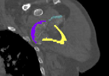
Glenoid Bone Loss in Reverse Shoulder Arthroplasty Treated with Bone Graft Techniques
ABSTRACT
The reverse shoulder arthroplasty facilitates surgical treatment of primary and revision shoulder with rotator cuff and bone deficiencies. Wear pattern classifications and a logical treatment approach for glenoid bone loss enable the surgeon to address a difficult series of problems in the reconstructions where the glenoid might not otherwise be able to support the implants. Bone grafting using the native humeral head in primary cases, and in revision cases, iliac crest are the most reliable sources for structural grafts for the worn or deficient glenoid vault.
Continue to: The reverse shoulder arthroplasty...
The reverse shoulder arthroplasty (RSA) technique was approved by the US Food and Drug Administration and introduced to the US market in 2004. It has been a successful addition to the treatment of shoulder pathologies with bone and rotator cuff loss. Its indications have expanded from treatment of very elderly patients with rotator cuff deficiencies to now include younger patients with humeral and glenoid bone loss, arthritis, soft-tissue losses, fractures, instability, and revision arthroplasty. Many of these conditions, when not adequately addressed with anatomic arthroplasty, now have viable treatment options for newer complex and successful reconstructions.
Glenoid bone deficiencies offer unique challenges for successful arthroplasty management. Basing treatment on bone loss classifications permits meaningful evaluation of these surgical options and whether they might be carried out in 1- or 2-stage reconstructions. An underlying premise is that restoration of the glenoid joint line and version assist in final stability, power, and functional results. For this purpose, bone graft options, or augmented implants are beneficial. This review covers the bone grafting options for autografts and allografts for deficient glenoids in reverse shoulder arthroplasty reconstructions.
OPERATIVE TECHNIQUES
For patients without prior arthroplasty, the humeral head is available for bone grafting the glenoid bone deficits. Favard and Hamada have described vertical glenoid classifications for uneven glenoid bone loss applicable to cuff tear arthropathy and inflammatory arthritis patients.1,2 The more severe E3 superior and medial bone loss is ideally addressed with the humeral head. An early example in 2004 confirmed that this was a good indication for glenoid bone grafting and using the reverse shoulder in these advanced cases (Figures 1A-1E).

In this case, it was noted that with bone grafts the base plate post did not engage the native scapula glenoid vault. Given that the on-growth central post was the strongest part of the fixation, it was fortunate that this healed. The need for a longer post with bone grafts was recognized. Laurent Comtat with the Wright Medical company accommodated the author’s request to develop the first 25- and 30-mm-long posts to allow better fixation and on-growth potential when used with bone grafts.
Gilles Walch’s classification addresses arthritic central and horizontal bone loss.3,4 Considerations relevant in RSA include the severe A2 central bone loss found in inflammatory arthritis and the B2, B3, and C patterns with posterior bone loss seen in osteoarthritis, rheumatoid arthritis, and congenital dysplasia5,6 as seen in Figures 2A, 2B. The 3-dimensional (3-D) computed tomography (CT) scan is considered the most accurate method of assessment when compared with axial radiographs.7 The glenoid vault model as a measurement of glenoid bone loss has great promise in designing prosthetic replacements and bone graft techniques.8
 A B2 posteriorly eroded biconcave glenoid. (B) A B3 progressive posteriorly eroded glenoid with more medial wear and less fixed posterior subluxation.")
Continue to: Modern methods for determining glenoid version...
Modern methods for determining glenoid version, medialization, and eccentric bone wear include 3-D reconstruction and patient-specific instruments. For many years, version determination has been confirmed at surgery with subscapularis elevation, palpating the glenoid center point along Friedman’s line, and then inserting a Steinmann pin as a guide to restore version and the lateral joint line at the time of bone grafting. An example of this is demonstrated in Figures 3A-3E.9

All grafts are harvested with a hole saw from the humeral head. The inner diameter is 29 mm, the same as that of the base plate. Originally, the hole saw and mandrel were obtained from the hardware store, but Pascal Boileau upgraded the hole saw quality when he had industry develop a stainless-steel hole saw and published his results with the BIO-RSA (Wright Medical).10 In an unpublished study, Harmsen reviewed our 220 consecutive humeral head bone grafts for use of this technique with successful and reproducible results. In a separate evaluation, 29 shaped humeral head bone grafts for B2, B3, and C glenoid bone deficits showed 100% healing.11 This technique has good reproducibility when performed with an autogenous bone graft from a local donor source.
The more challenging cases involve glenoid bone loss from polyethylene osteolysis and, in some revision cases, concomitant sepsis.12 The humeral head is no longer available, and the distal clavicle or humeral metaphysis are often insufficient to restore the glenoid vault and joint line. Gunther and associates at the UC Berkeley biomaterials laboratory have made many contributions to our understanding of polyethylene wear and the factors leading to its loosening that result in massive glenoid bone loss.13
Antuna and colleagues14 classified these cases as having a central vault cavitary defect, or one combined with a peripheral glenoid wall bone loss of either the anterior or posterior glenoid. Newton and colleagues15 described the structural tricortical iliac crest bone graft as a 2-stage reconstruction. The second stage could be performed 4 to 6 months later after graft incorporation. With the excellent Association for Osteosynthesis (AO) type fixation using the base plate with compression and locking screws, it was reasonable to perform this in 1 stage, assuming that adequate fixation could be obtained with the iliac bone graft to the glenoid.16 This worked well with the cavitary glenoid defects and those in which either the anterior or posterior wall was absent.17-19
EXCEPTIONS TO THE 1-STAGE FIXATION TECHNIQUE
Fixation could still be obtained medially, but more severe cases were encountered with loss of both the anterior and posterior walls. In these more advanced cases, the vault was no longer present after removal of the polyethylene, cement, and rubbery osteolytic tissue that replaced the bone. To account for this, a simplified 3-stage classification was proposed.20 The cavitary vault defect is designated as type 1 bone loss. Type 2A includes the cavitary central defect plus loss of the anterior glenoid wall, and 2B is similar with loss of the posterior wall (Figures 4A-4F). Type 3 involves loss of the glenoid vault and both anterior and posterior walls with erosion down to the medial juncture of the base of the scapular spine, coracoid, and pillar of the scapula.
 in revision total shoulder arthroplasty")
Continue to: The tricortical iliac crest bone graft...
The tricortical iliac crest bone graft (TICBG) offered a structural graft that worked well for these cases of bone loss. When the graft is performed in 1 stage, the glenoid is exposed, and the defect measured after removing the osteolytic, polyethylene-laden tissue from the glenoid. The iliac graft is harvested and placed with the long post base plate engaging the native scapula medially (Figures 5A-5C).

This technique worked well with the type 1 and 2 defects, but when attempted with the type 3 glenoid defect with global glenoid bone loss, adequate fixation for a single-stage reconstruction could not be predictably obtained with type 3 loss of the vault and both walls. In this situation, the base plate post is wider than the remaining medialized glenoid vault (Figures 6A-6C). The iliac crest provides better bone for this global loss when harvested sideways, fixed with screws, and after secure healing, the second-stage base plate is placed (Figures 7A-7F).

An alternative to the iliac crest as a bone graft donor site is the femoral neck allograft.21 It avoids the additional surgery and pain at the donor site, but healing is less assured. Scalise and Iannotti22 have had good clinical results but noted substantial graft resorption when revising a total shoulder to a humeral head arthroplasty. In a recent report by Ozgur and colleagues,23 64% of femoral neck allografts were still intact at 1-year follow-up. The technique involved harvesting the graft with a hole saw, shaping and affixing it to the deficient glenoid, and gaining central fixation with a threaded or solid post base plate and peripheral screws. Poor results were obtained with the use of the femoral shaft, as it is brittle. Angled peripheral screws caused the allograft shaft to fracture. Low-grade sepsis remained an unanswered problem in the patient group, which averaged 6 prior procedures, and often led to another revision. Less favorable results were found using the 1-piece threaded post base plate with grafts.24 It is assumed that the allograft has less healing potential, and micro motion plays a role when the long central screw has no on-growth healing potential in the native scapula. This graft choice is the author’s least favorite, but is available in desperate situations. Jones and colleagues25 report promising results with bulk allografts and autografts for large glenoid defects with good clinical results. The results in the graft cohort were inferior to those in a matched group not requiring grafts. Their complications were consistent with the revision setting for shoulders having multiple operations. It is well known that preoperative factors are strong predictors of postoperative outcomes.26

CONCLUSION
The author’s current technique is to use the native humeral head when available, or iliac crest for structural support to the base plate and glenosphere. Secure fixation to the native scapula is necessary if the operation is to be done in 1-stage. Incorporation with calcium orthophosphate bone substitution does not replace the need for structural support as shown in Figures 8A-8D.

For the type 2 vault and 1 wall glenoid bone loss defects, the TICBG is still the most useful option. For the type 3 global bone loss defects, a 2-stage approach is the safer option. Additional options that may replace some of these grafting techniques are the introduction of the metallic augmented ingrowth base plates to correct for superior, anterior, and posterior glenoid bone losses. The early unpublished experiences by Wright and colleagues are very promising. All of the above options should be available in the operating room for a busy arthroplasty surgeon.
1. Hamada K, Fukuda H, Mikasa M, Kobay Y. Roentgenographic findings in massive rotator cuff tears. A long-term observation. Clin Orthop Relat Res. 1990;254:92-96.
2. Favard L, Alami G. The glenoid in the frontal plane: The Favard and Hamada radiographic classifications of cuff tear osteoarthritis. In: Walch G, Boileau P, Favard ML, Lévigne C, Sirveaux F, eds. Shoulder Concepts 2010: The Glenoid. Paris, France: Sauramps Medical; 2010:53-58.
3. Rouleau DM, Kidder JF, Pons-Villanueva J, Dynamidis S, Walch G. The glenoid in the horizontal plane: Walch classification revisited humeral subluxation and glenoid retroversion. In: Walch G, Boileau P, Favard ML, Lévigne C, Sirveaux F, eds. Shoulder Concepts 2010: The Glenoid. Paris, France: Sauramps Medical; 2010:45-51.
4. Walch G, Badet R, Boulahia A, Khoury A. Morphological study of the glenoid in primary glenohumeral osteoarthritis. J Arthroplasty. 1999;14(6):756-760.
5. Iannotti JP, Ricchetti E. Walch classification: adding two new glenoid types. Orthopaedic Insights Cleveland Clinic. 2017:6-7.
6. Mizuno N, Denard PJ, Raiss P, Walch G. Reverse shoulder arthroplasty for primary glenohumeral osteoarthritis with a biconcave glenoid. J Bone Joint Surg Am. 2013;95(14):1297-1304.
7. Nyffeler RW, Jost B, Pfirrmann CW, Gerber C. Measurement of glenoid version: conventional radiographs verses computed tomography scans. J Shoulder Elbow Surg. 2003;12(5):493-496.
8. Scalise JJ, Bryan J, Polster J, Brems JJ, Iannotti JP. Quantitative analysis of glenoid bone loss in osteoarthritis using three-dimensional compute tomography scans. [published online ahead of print January 22, 2008]. J Shoulder Elbow Surg. 2008;17(2):328-335.
9. Friedman RJ, Hawthorne KB, Genez BM. The use of computerized tomography in the measurement of glenoid version. J Bone Joint Surg Am. 1992;74(7):1032-1037.
10. Boileau P, Moineau G, Roussanne Y, O’Shea K. Bony increased-offset reverse shoulder arthroplasty: minimizing scapular impingement while maximizing glenoid fixation. Clin Orthop Relat Res. 2011;469(9):2558-2567.
11. Harmsen S, Casagrande D, Norris T: “Shaped” humeral head autograft reverse shoulder arthroplasty: Treatment for primary glenohumeral osteoarthritis with significant posterior glenoid bone loss (B2, B3, and C-type). Orthopade. 2017;46(12):1045-1054.
12. Norris TR, Phipatanakul WP. Treatment of glenoid loosening and bone loss due to osteolysis with glenoid bone grafting. J Shoulder Elbow Surg. 2006;15(1):84-87.
13. Farzana F, Lee T, Malito L, et al. Analysis of severely fractured glenoid components: clinical consequences of biomechanics, design, and materials selection on implant performance. J Shoulder Elbow Surg. 2016;25(7):1041-1050.
14. Antuña SA, Sperling JW, Cofield RH, Rowland CM. Glenoid revision surgery after total shoulder arthroplasty. J Shoulder Elbow Surg. 2001;10(3):217-224.
15. Newton L, Walch G, Nove-Josserand L, Edwards TB. Glenoid cortical cancellous bone grafting after glenoid component removal in the treatment of glenoid loosening. J Shoulder Elbow Surg. 2006;15(2):173-179.
16. Norris TR, Kelly JD, Humphrey CS. Management of glenoid bone defects in revision shoulder arthroplasty: a new application of the reverse total shoulder prosthesis. Techniques Shoulder Elbow Surgery. 2007;8(1):37-46.
17. Kelly JD II, Zhao JX, Hobgood ER, Norris TR. Clinical results of revision shoulder arthroplasty using the reverse prosthesis. J Shoulder Elbow Surg. 2012;21(11):1516-1525.
18. Norris TR. Reconstruction of glenoid bone loss in total shoulder arthroplasty. In: Boileau P, ed. Shoulder Concepts 2008-Arthroscopy and Arthroplasty. Paris, France: Sauramps Medical; 2008:397-404.
19. Humphrey CS, Kelly JD, Norris TR. Management of glenoid deficiency in reverse shoulder arthroplasty. In: Fealy S, Warren RF, Craig EV, Sperling JW, eds. Shoulder Arthroplasty. New York, NY: Thieme; 2006.
20. Norris TR, Abdus-Salaam S. Lessons learned from the Hylamer experience and technical salvage for glenoid reconstruction. In: Walch G, Boileau P, Favard ML, Lévigne C, Sirveaux F, eds. Shoulder Concepts 2010: The Glenoid. Paris, France: Sauramps Medical; 2010:265-278.
21. Bateman E, Donald SM. Reconstruction of massive uncontained glenoid defects using a combined autograft-allograft construct with reverse shoulder arthroplasty: preliminary results. J Shoulder Elbow Surg. 2012;21(7):925-934.
22. Scalise JJ, Iannotti JP. Bone grafting severe glenoid defects in revision shoulder arthroplasty. Clin Orthop. 2008;466(1):139-145.
23. Ozgur S, Sadeghpour R, Norris TR. Revision shoulder arthroplasty with a reverse shoulder prosthesis. Use of structural allograft for glenoid bone loss. Orthopade. 2017;46(12):1055-1062.
24. Sadeghpour R, Ozgur S, Norris TR. Threaded post baseplate failures in RSA. In: Hardy PH, Valenti PH, Scheibel M, eds. Shoulder Arthroplasty, Current Concepts. Paris International Shoulder Course 2017. 2017:148-157.
25. Jones RB, Wright TW, Zuckerman JD. Reverse total shoulder arthroplasty with structural bone grafting of large glenoid defects. J Shoulder Elbow Surg. 2016;25(9):1425-1432.
26. Iannotti JP, Norris TR. Influence of preoperative factors on outcome of shoulder arthroplasty for glenohumeral osteoarthritis. J Bone Joint Surg. 2003;85(2):251-258.
ABSTRACT
The reverse shoulder arthroplasty facilitates surgical treatment of primary and revision shoulder with rotator cuff and bone deficiencies. Wear pattern classifications and a logical treatment approach for glenoid bone loss enable the surgeon to address a difficult series of problems in the reconstructions where the glenoid might not otherwise be able to support the implants. Bone grafting using the native humeral head in primary cases, and in revision cases, iliac crest are the most reliable sources for structural grafts for the worn or deficient glenoid vault.
Continue to: The reverse shoulder arthroplasty...
The reverse shoulder arthroplasty (RSA) technique was approved by the US Food and Drug Administration and introduced to the US market in 2004. It has been a successful addition to the treatment of shoulder pathologies with bone and rotator cuff loss. Its indications have expanded from treatment of very elderly patients with rotator cuff deficiencies to now include younger patients with humeral and glenoid bone loss, arthritis, soft-tissue losses, fractures, instability, and revision arthroplasty. Many of these conditions, when not adequately addressed with anatomic arthroplasty, now have viable treatment options for newer complex and successful reconstructions.
Glenoid bone deficiencies offer unique challenges for successful arthroplasty management. Basing treatment on bone loss classifications permits meaningful evaluation of these surgical options and whether they might be carried out in 1- or 2-stage reconstructions. An underlying premise is that restoration of the glenoid joint line and version assist in final stability, power, and functional results. For this purpose, bone graft options, or augmented implants are beneficial. This review covers the bone grafting options for autografts and allografts for deficient glenoids in reverse shoulder arthroplasty reconstructions.
OPERATIVE TECHNIQUES
For patients without prior arthroplasty, the humeral head is available for bone grafting the glenoid bone deficits. Favard and Hamada have described vertical glenoid classifications for uneven glenoid bone loss applicable to cuff tear arthropathy and inflammatory arthritis patients.1,2 The more severe E3 superior and medial bone loss is ideally addressed with the humeral head. An early example in 2004 confirmed that this was a good indication for glenoid bone grafting and using the reverse shoulder in these advanced cases (Figures 1A-1E).
In this case, it was noted that with bone grafts the base plate post did not engage the native scapula glenoid vault. Given that the on-growth central post was the strongest part of the fixation, it was fortunate that this healed. The need for a longer post with bone grafts was recognized. Laurent Comtat with the Wright Medical company accommodated the author’s request to develop the first 25- and 30-mm-long posts to allow better fixation and on-growth potential when used with bone grafts.
Gilles Walch’s classification addresses arthritic central and horizontal bone loss.3,4 Considerations relevant in RSA include the severe A2 central bone loss found in inflammatory arthritis and the B2, B3, and C patterns with posterior bone loss seen in osteoarthritis, rheumatoid arthritis, and congenital dysplasia5,6 as seen in Figures 2A, 2B. The 3-dimensional (3-D) computed tomography (CT) scan is considered the most accurate method of assessment when compared with axial radiographs.7 The glenoid vault model as a measurement of glenoid bone loss has great promise in designing prosthetic replacements and bone graft techniques.8
Continue to: Modern methods for determining glenoid version...
Modern methods for determining glenoid version, medialization, and eccentric bone wear include 3-D reconstruction and patient-specific instruments. For many years, version determination has been confirmed at surgery with subscapularis elevation, palpating the glenoid center point along Friedman’s line, and then inserting a Steinmann pin as a guide to restore version and the lateral joint line at the time of bone grafting. An example of this is demonstrated in Figures 3A-3E.9
All grafts are harvested with a hole saw from the humeral head. The inner diameter is 29 mm, the same as that of the base plate. Originally, the hole saw and mandrel were obtained from the hardware store, but Pascal Boileau upgraded the hole saw quality when he had industry develop a stainless-steel hole saw and published his results with the BIO-RSA (Wright Medical).10 In an unpublished study, Harmsen reviewed our 220 consecutive humeral head bone grafts for use of this technique with successful and reproducible results. In a separate evaluation, 29 shaped humeral head bone grafts for B2, B3, and C glenoid bone deficits showed 100% healing.11 This technique has good reproducibility when performed with an autogenous bone graft from a local donor source.
The more challenging cases involve glenoid bone loss from polyethylene osteolysis and, in some revision cases, concomitant sepsis.12 The humeral head is no longer available, and the distal clavicle or humeral metaphysis are often insufficient to restore the glenoid vault and joint line. Gunther and associates at the UC Berkeley biomaterials laboratory have made many contributions to our understanding of polyethylene wear and the factors leading to its loosening that result in massive glenoid bone loss.13
Antuna and colleagues14 classified these cases as having a central vault cavitary defect, or one combined with a peripheral glenoid wall bone loss of either the anterior or posterior glenoid. Newton and colleagues15 described the structural tricortical iliac crest bone graft as a 2-stage reconstruction. The second stage could be performed 4 to 6 months later after graft incorporation. With the excellent Association for Osteosynthesis (AO) type fixation using the base plate with compression and locking screws, it was reasonable to perform this in 1 stage, assuming that adequate fixation could be obtained with the iliac bone graft to the glenoid.16 This worked well with the cavitary glenoid defects and those in which either the anterior or posterior wall was absent.17-19
EXCEPTIONS TO THE 1-STAGE FIXATION TECHNIQUE
Fixation could still be obtained medially, but more severe cases were encountered with loss of both the anterior and posterior walls. In these more advanced cases, the vault was no longer present after removal of the polyethylene, cement, and rubbery osteolytic tissue that replaced the bone. To account for this, a simplified 3-stage classification was proposed.20 The cavitary vault defect is designated as type 1 bone loss. Type 2A includes the cavitary central defect plus loss of the anterior glenoid wall, and 2B is similar with loss of the posterior wall (Figures 4A-4F). Type 3 involves loss of the glenoid vault and both anterior and posterior walls with erosion down to the medial juncture of the base of the scapular spine, coracoid, and pillar of the scapula.
Continue to: The tricortical iliac crest bone graft...
The tricortical iliac crest bone graft (TICBG) offered a structural graft that worked well for these cases of bone loss. When the graft is performed in 1 stage, the glenoid is exposed, and the defect measured after removing the osteolytic, polyethylene-laden tissue from the glenoid. The iliac graft is harvested and placed with the long post base plate engaging the native scapula medially (Figures 5A-5C).
This technique worked well with the type 1 and 2 defects, but when attempted with the type 3 glenoid defect with global glenoid bone loss, adequate fixation for a single-stage reconstruction could not be predictably obtained with type 3 loss of the vault and both walls. In this situation, the base plate post is wider than the remaining medialized glenoid vault (Figures 6A-6C). The iliac crest provides better bone for this global loss when harvested sideways, fixed with screws, and after secure healing, the second-stage base plate is placed (Figures 7A-7F).
An alternative to the iliac crest as a bone graft donor site is the femoral neck allograft.21 It avoids the additional surgery and pain at the donor site, but healing is less assured. Scalise and Iannotti22 have had good clinical results but noted substantial graft resorption when revising a total shoulder to a humeral head arthroplasty. In a recent report by Ozgur and colleagues,23 64% of femoral neck allografts were still intact at 1-year follow-up. The technique involved harvesting the graft with a hole saw, shaping and affixing it to the deficient glenoid, and gaining central fixation with a threaded or solid post base plate and peripheral screws. Poor results were obtained with the use of the femoral shaft, as it is brittle. Angled peripheral screws caused the allograft shaft to fracture. Low-grade sepsis remained an unanswered problem in the patient group, which averaged 6 prior procedures, and often led to another revision. Less favorable results were found using the 1-piece threaded post base plate with grafts.24 It is assumed that the allograft has less healing potential, and micro motion plays a role when the long central screw has no on-growth healing potential in the native scapula. This graft choice is the author’s least favorite, but is available in desperate situations. Jones and colleagues25 report promising results with bulk allografts and autografts for large glenoid defects with good clinical results. The results in the graft cohort were inferior to those in a matched group not requiring grafts. Their complications were consistent with the revision setting for shoulders having multiple operations. It is well known that preoperative factors are strong predictors of postoperative outcomes.26
CONCLUSION
The author’s current technique is to use the native humeral head when available, or iliac crest for structural support to the base plate and glenosphere. Secure fixation to the native scapula is necessary if the operation is to be done in 1-stage. Incorporation with calcium orthophosphate bone substitution does not replace the need for structural support as shown in Figures 8A-8D.
For the type 2 vault and 1 wall glenoid bone loss defects, the TICBG is still the most useful option. For the type 3 global bone loss defects, a 2-stage approach is the safer option. Additional options that may replace some of these grafting techniques are the introduction of the metallic augmented ingrowth base plates to correct for superior, anterior, and posterior glenoid bone losses. The early unpublished experiences by Wright and colleagues are very promising. All of the above options should be available in the operating room for a busy arthroplasty surgeon.
1. Hamada K, Fukuda H, Mikasa M, Kobay Y. Roentgenographic findings in massive rotator cuff tears. A long-term observation. Clin Orthop Relat Res. 1990;254:92-96.
2. Favard L, Alami G. The glenoid in the frontal plane: The Favard and Hamada radiographic classifications of cuff tear osteoarthritis. In: Walch G, Boileau P, Favard ML, Lévigne C, Sirveaux F, eds. Shoulder Concepts 2010: The Glenoid. Paris, France: Sauramps Medical; 2010:53-58.
3. Rouleau DM, Kidder JF, Pons-Villanueva J, Dynamidis S, Walch G. The glenoid in the horizontal plane: Walch classification revisited humeral subluxation and glenoid retroversion. In: Walch G, Boileau P, Favard ML, Lévigne C, Sirveaux F, eds. Shoulder Concepts 2010: The Glenoid. Paris, France: Sauramps Medical; 2010:45-51.
4. Walch G, Badet R, Boulahia A, Khoury A. Morphological study of the glenoid in primary glenohumeral osteoarthritis. J Arthroplasty. 1999;14(6):756-760.
5. Iannotti JP, Ricchetti E. Walch classification: adding two new glenoid types. Orthopaedic Insights Cleveland Clinic. 2017:6-7.
6. Mizuno N, Denard PJ, Raiss P, Walch G. Reverse shoulder arthroplasty for primary glenohumeral osteoarthritis with a biconcave glenoid. J Bone Joint Surg Am. 2013;95(14):1297-1304.
7. Nyffeler RW, Jost B, Pfirrmann CW, Gerber C. Measurement of glenoid version: conventional radiographs verses computed tomography scans. J Shoulder Elbow Surg. 2003;12(5):493-496.
8. Scalise JJ, Bryan J, Polster J, Brems JJ, Iannotti JP. Quantitative analysis of glenoid bone loss in osteoarthritis using three-dimensional compute tomography scans. [published online ahead of print January 22, 2008]. J Shoulder Elbow Surg. 2008;17(2):328-335.
9. Friedman RJ, Hawthorne KB, Genez BM. The use of computerized tomography in the measurement of glenoid version. J Bone Joint Surg Am. 1992;74(7):1032-1037.
10. Boileau P, Moineau G, Roussanne Y, O’Shea K. Bony increased-offset reverse shoulder arthroplasty: minimizing scapular impingement while maximizing glenoid fixation. Clin Orthop Relat Res. 2011;469(9):2558-2567.
11. Harmsen S, Casagrande D, Norris T: “Shaped” humeral head autograft reverse shoulder arthroplasty: Treatment for primary glenohumeral osteoarthritis with significant posterior glenoid bone loss (B2, B3, and C-type). Orthopade. 2017;46(12):1045-1054.
12. Norris TR, Phipatanakul WP. Treatment of glenoid loosening and bone loss due to osteolysis with glenoid bone grafting. J Shoulder Elbow Surg. 2006;15(1):84-87.
13. Farzana F, Lee T, Malito L, et al. Analysis of severely fractured glenoid components: clinical consequences of biomechanics, design, and materials selection on implant performance. J Shoulder Elbow Surg. 2016;25(7):1041-1050.
14. Antuña SA, Sperling JW, Cofield RH, Rowland CM. Glenoid revision surgery after total shoulder arthroplasty. J Shoulder Elbow Surg. 2001;10(3):217-224.
15. Newton L, Walch G, Nove-Josserand L, Edwards TB. Glenoid cortical cancellous bone grafting after glenoid component removal in the treatment of glenoid loosening. J Shoulder Elbow Surg. 2006;15(2):173-179.
16. Norris TR, Kelly JD, Humphrey CS. Management of glenoid bone defects in revision shoulder arthroplasty: a new application of the reverse total shoulder prosthesis. Techniques Shoulder Elbow Surgery. 2007;8(1):37-46.
17. Kelly JD II, Zhao JX, Hobgood ER, Norris TR. Clinical results of revision shoulder arthroplasty using the reverse prosthesis. J Shoulder Elbow Surg. 2012;21(11):1516-1525.
18. Norris TR. Reconstruction of glenoid bone loss in total shoulder arthroplasty. In: Boileau P, ed. Shoulder Concepts 2008-Arthroscopy and Arthroplasty. Paris, France: Sauramps Medical; 2008:397-404.
19. Humphrey CS, Kelly JD, Norris TR. Management of glenoid deficiency in reverse shoulder arthroplasty. In: Fealy S, Warren RF, Craig EV, Sperling JW, eds. Shoulder Arthroplasty. New York, NY: Thieme; 2006.
20. Norris TR, Abdus-Salaam S. Lessons learned from the Hylamer experience and technical salvage for glenoid reconstruction. In: Walch G, Boileau P, Favard ML, Lévigne C, Sirveaux F, eds. Shoulder Concepts 2010: The Glenoid. Paris, France: Sauramps Medical; 2010:265-278.
21. Bateman E, Donald SM. Reconstruction of massive uncontained glenoid defects using a combined autograft-allograft construct with reverse shoulder arthroplasty: preliminary results. J Shoulder Elbow Surg. 2012;21(7):925-934.
22. Scalise JJ, Iannotti JP. Bone grafting severe glenoid defects in revision shoulder arthroplasty. Clin Orthop. 2008;466(1):139-145.
23. Ozgur S, Sadeghpour R, Norris TR. Revision shoulder arthroplasty with a reverse shoulder prosthesis. Use of structural allograft for glenoid bone loss. Orthopade. 2017;46(12):1055-1062.
24. Sadeghpour R, Ozgur S, Norris TR. Threaded post baseplate failures in RSA. In: Hardy PH, Valenti PH, Scheibel M, eds. Shoulder Arthroplasty, Current Concepts. Paris International Shoulder Course 2017. 2017:148-157.
25. Jones RB, Wright TW, Zuckerman JD. Reverse total shoulder arthroplasty with structural bone grafting of large glenoid defects. J Shoulder Elbow Surg. 2016;25(9):1425-1432.
26. Iannotti JP, Norris TR. Influence of preoperative factors on outcome of shoulder arthroplasty for glenohumeral osteoarthritis. J Bone Joint Surg. 2003;85(2):251-258.
TAKE-HOME POINTS
- Glenoid deficiencies that occur from dysplasia, arthritis, or polyethylene osteolysis may be successfully addressed with bone grafting techniques and reverse shoulder arthroplasty.
- The intact humeral head in a primary case is ideal graft to be shaped to fit the glenoid deficits.
- The reverse shoulder with a long post base plate that is fixed securely to the native scapula is the author’s preferred technique.
- As the native humeral head is not available in revision cases, the tricortical iliac crest bone graft may be fixed as a structural graft in 1-stage.
- When the scapular walls are deficient and medial fixation is not secure, 2 stages 4 months to 6 months apart will be necessary before loading the construct.

Managing Glenoid Bone Deficiency—The Augment Experience in Anatomic and Reverse Shoulder Arthroplasty
ABSTRACT
Glenoid bone deficiency in the setting of shoulder replacement surgery is far more common than originally reported. The frequency and severity of the glenoid defects are noted to be more common and severe with the advent of computer-assisted surgery. The results of an anatomic total shoulder arthroplasty (aTSA) with glenoid deficiency have been reported to be inferior to aTSA patients without a glenoid deficiency. Options for treating the glenoid deficiency include eccentric reaming, bone grafting, and the use of augmented glenoid components. The purpose of this article is to present the indications, technique, and results of augmented glenoids for both aTSA and reverse TSA (RTSA).
Augments for both aTSA and RTSA are viable options. They preserve subchondral bone at the same time as optimizing the joint line without the need for bone grafts. Complications, revisions and results are as good as compared to shoulder arthroplasties without glenoid wear.
Continue to: Glenoid bone deficiency...
Glenoid bone deficiency in arthritic or cuff-deficient shoulder has been reported in up to 50% of shoulder defect cases.1,2 The type and severity of glenoid deformities vary depending on the underlying pathology and time of manifestation. Osteoarthritis with bone loss typically results in posterior or posterior inferior glenoid wear and is commonly classified as Walch types B1 or B2 (biconcave). In cases of severe erosion, B3 classification has been proposed; in this classification, bone loss becomes extremely severe, progressing to resemble a type C glenoid. Unlike primary osteoarthritis, inflammatory arthropathy more commonly causes central loss of glenoid bone (Walch A2). With the rotator cuff insufficiency, superior migration of the humeral head occurs. As these conditions progress, cuff tear arthropathy (CTA) changes result in superior or posterior-superior bone loss.1 Anterior bone loss (type D) will be rarely encountered due to recurrent anterior instability.3
Classically, with anatomic total shoulder arthroplasty (aTSA), the surgeon considers several options for managing glenoid deficiencies. The most commonly employed technique involves eccentrically reaming the glenoid and correcting the deformity. This procedure is relatively easy but features significant drawbacks, such as sacrificing the subchondral bone, medializing the glenohumeral joint line, and secondarily shrinking the glenoid surface area. Other options include structural bone grafting behind the glenoid component. Most anatomic prosthetic glenoids prove to be unsuitable for fixation of structural bone graft. Therefore, the graft is first internally fixed, followed by placement of the glenoid component. Cement, which is commonly used for glenoid fixation, may potentially inhibit bone-graft healing. Reports using this technique documented high radiographic failure rate of up to 40% at midterm follow-up.4 Although leaving the glenoid component retroverted may be considered, surgeons should develop awareness of the possibility of peg penetration of the anterior glenoid neck. Additionally, retroversion in excess of 5°may increase the risk of recurrent posterior subluxation, resulting in early glenoid loosening.5-7 Results of aTSA under significant glenoid deficiency are inferior to those of aTSA patients without glenoid deficiency.8 Such findings have been extremely inferior in patients with significant glenoid wear, prompting numerous surgeons to abandon aTSA in this population in favor of reverse TSA (RTSA) due to improved bony fixation.
In 2010, augmented anatomic glenoids were first introduced as a wedge (Exactech) and as a step shortly thereafter (DePuy Synthes; Figures 1A-1C). More recently, hemi-wedges have been introduced (Wright Medical Group). Augments have gained popularity due to improved range of motion vs reverse shoulder arthroplasty (RSA). However, debates remain regarding the use of posteriorly augmented components in the setting of posterior glenoid bone loss.8 Augments serve as another viable option for handling glenoid bone deficiency in aTSA.

Glenoid bone loss in RTSA presents similar options to aTSA. However, screw fixation of the glenoid component offers several distinct advantages. Baseplate fixation can readily be used with bone grafting and with a highly anticipated success rate. With multiple screw options, 100% support of the baseplate is not mandatory. Although bony increase offset RSAs (BIO-RSAs) have shown success, augmentation with allograft or autograft increases operative time and relies on osseous integration for long-term implant success.9 Metal augmented baseplates were first introduced in 2011 (Exactech) as a means of managing glenoid bone loss without structural grafting. Although initial results have been encouraging, additional studies are needed to assess the longevity of these implants (Figures 1A-1C).
aTSA AUGMENTS
aTSA augments were introduced as a means of correcting acquired glenoid bone deficiency, restoring native glenoid version, correcting humeral subluxation, and preserving the native subchondral bone. Compared with glenoid bone grafting, augmented glenoid components decrease operative time, allow for a technically easier operation, and require no bone healing for clinical success. Early and midterm results are encouraging, showing similar findings comparable to those of aTSA in non-glenoid deficient shoulders.10-12
Continue to: INDICATIONS
INDICATIONS
Indications and limitations for augmented aTSA glenoids remain incompletely defined. The most common indication for an augmented aTSA is osteoarthritis with a B2 glenoid. We recommend augments in the occurrence of any indication of significant eccentric glenoid wear. With the expertise of surgeons, deformities of up to 20° to 25° of deformity can be readily handled with good predictability. More severe deformities can be managed with augmented aTSA components, but early failure rates may be high. The most severe acquired deformities remain best managed with RTSA. Currently, we prefer RTSA when glenoid bone loss exceeds 25°. With the widespread availability of computed tomography (CT) scans with 3-dimensional (3-D) reconstruction, glenoid bone defects are increasingly recognized. When correcting deformity, surgeons should strive to limit residual retroversion to a maximum of 5°.13 Preoperative planning software and computer-assisted surgery (ExactechGPS) may allow surgeons to better define the limits of augmented glenoid fixation prior to the date of surgery. We routinely utilize computer-guided glenoid preparation to control glenoid version to within 5° of neutral position.
The differences between B3 and a true type C glenoid must be recognized. Although B3 glenoids may still be a candidate for an augmented anatomic glenoid component, type C glenoids are not. Developmental abnormalities of type C glenoid occur simultaneously with humeral deformities, including medialized posterior rotator cuff musculature. Correction of the joint line to neutral version may not replicate the non-diseased state of a dysplastic type shoulder. Davis and colleagues14 have proposed treating these patients by leaving both the humerus and glenoid in their native version without correction.
TECHNIQUE
The implant that we have the most experience with is an 8° full-wedge augmented glenoid component. Such an implant is typically utilized for B2 glenoids. We recommend that a high-quality CT scan be performed for preoperative planning. As a general rule, the starting point often lies close to the ridge of B2 glenoid and more anterior than the apparent glenoid center, which is viewed intraoperatively due to asymmetric posterior wear. Full-wedge component is utilized to ream the ridge separating the neo and paleoglenoids to create a flat surface. This condition is best achieved by drilling a pilot hole at the planned glenoid central peg position to prevent the reamer from sliding anteriorly during reaming. Glenoid preparation begins with the smallest reamer until the ridge has been flattened, and the reamer makes full contact with the glenoid. The reamer diameter is then increased based on glenoid size. Slightly downsizing the glenoid implant will require less reaming to achieve full backside support. Once the glenoid is properly reamed, the central and peripheral peg holes are drilled using the appropriate guides. Holes are then dried, and all-polyethylene or composite glenoid component (either partially or completely cemented) is installed using favored cementing techniques. The advantage of composite glenoid component is that the central cage allows for bone ingrowth and may potentially improve long-term implant survival. Press fit of the central cage requires no waiting time for glenoid cement hardening before proceeding to the humerus. When placing an augmented component, adequate glenoid exposure is imperative to allow in-line placement and appropriate seating of the component without impingement on adjacent retractors.
When using the step-augmented glenoid, the paleoglenoid is prepared in a similar fashion to a standard aTSA. Once the paleoglenoid has been reamed to a neutral position, a protector plate is placed onto the paleoglenoid. and a step-cut saw is used to prepare the posterior stepped bone cut. Peripheral pegs are then drilled, and the component is installed in routine fashion. When using hemi-wedge augments, the paleoglenoid is again prepared in a similar fashion as a standard glenoid component over a cannulated guidewire. The neoglenoid is subsequently prepared using a specialized angled reamer with a positive stop to prevent over-reaming. These glenoid implants improve rotational force neutralization given the absence of flat back against the glenoid. All 3 designs preserve bone when compared with eccentric reaming alone,15 with the half-augmented wedge preserving the most bone.
Table 1. Results of Various Augmented Glenoid Components in Anatomic Total Shoulder
Arthroplasty
| Augment | American Shoulder and Elbow Surgeons Score | Constant Score | Active Forward Flexion | Active External Rotation | ||||||||||||||||
8° cage (N = 21) |
|
|
|
|
| |||||||||||||||
All-polyethylene 8° (N = 45) |
|
|
|
|
| |||||||||||||||
All-polyethylene 16° (N = 7) |
|
|
|
|
|
RESULTS
In our institution, we first used all-polyethylene posteriorly augmented glenoid components in 2010. Between 2010 and 2015, 45 patients received an 8° all-polyethylene posterior augment, and 7 patients received a 16° augment. In 2015, we transitioned to the composite caged posterior augment. All patients in our database who received an augmented glenoid component experienced improvement in active forward elevation, external rotation, American Shoulder and Elbow Surgeons (ASES), and Constant scores (Table 1). Minimum follow-up was 1 year for patients receiving both an 8° cage (mean, 1.48 years) and an 8° all-polyethylene augment (mean, 3.18 years). Figures 2A-2C show a patient with significant posterior glenoid wear and humeral head subluxation treated with an 8° wedge composite posterior augment glenoid 3 years postoperative.

Continue to: COMPLICATIONS
COMPLICATIONS
Two complications developed in the group undergoing composite cage augment. One patient experienced glenoid loosening after a motor vehicle accident. Another patient sustained significant intraoperative tuberosity avulsion during implantation of the humeral component, requiring a change of implant and tuberosity fixation. Although no complications were noted in the 8° all-polyethylene group, 3 patients in the 16° augment group sustained complications. One of these patients suffered a cardiac event that was unrelated to the implant. Two complications in this group were both related to loosening of the glenoid component, requiring subsequent revision.
DISCUSSION
The first report on augmented aTSA was published in 2008, and it involved a 5° augmented, anatomic glenoid.12 One study was based on a small series of augments; the poor results led the reporting surgeons to subsequently abandon the implant.12 This early design produced a correction on the articular side of the implant rather than the pathologic bony side. By performing such correction, the component pegs remained anteriorly oriented, placing the component at risk of perforation through the anterior glenoid neck. All current augment designs feature pegs that are oriented down the glenoid vault, with corrections occurring on the bony surface. This condition requires 2 different axes for reaming the glenoid and drilling the pegs. This approach allows the pegs to be directed down the glenoid neck, and is a far superior solution to neutralizing shear forces when compared with the implants used in the 1990s.
Early to midterm results of modern aTSA augments have been extremely encouraging with low revision rates. The main concern of recurrent posterior subluxation has been rarely reported. The concerns over glenoid loosening due to high shear forces, similarly, have not been described to date. However, surgeons should remain cautious, as longer-term follow-up remains unavailable.
The main advantage of aTSA augments is their capacity to preserve bone compared with eccentric reaming and better long-term stability. Each of the augment designs requires varying amounts of bone removal. Through biomechanics and using finite element analysis, the 3 augment types act differently, with no design demonstrating remarkable biomechanical superiority.6 Favorito and colleagues16 performed a retrospective review of 22 patients who underwent aTSA using an all-polyethylene, posteriorly augmented, and stepped glenoid component for posterior bone loss. At an average follow-up of 36 months, all patients experienced improvements in active forward elevation, external rotation, visual analog scale, Short Form-36 Physical Component Summary, and Western Ontario Osteoarthritis of the Shoulder scores. The authors noted that 2 patients (9%) experienced complications: 1 with an anterior dislocation and the other with recurrent posterior instability requiring revision. Sandow and Schutz17 reported the preliminary results of 10 patients who underwent aTSA using trabecular metal augment with a minimum of 2-year follow-up. All patients received either a 15° or 30° posterior, metal-backed augment for severe glenoid bone loss (Walch grade B2 or C). At a minimum of 2-year follow-up, all patients received correction to within 10° of neutral glenoid version, without any complications nor implant failures.
Regardless of augment design, all current components restore the native glenoid version, improving the length and subsequent tension of rotator cuff musculature. Similarly, re-centering the humeral head decreases the forces on the glenoid and allows for optimal function with decreasing loss of vital subchondral bone.
Continue to: RTSA AUGMENTS
RTSA AUGMENTS
Similar to anatomic augments, metal augments were introduced for use with RTSA in 2011. Unlike anatomic augments, those for RTSA were manufactured with metal. Given the difference in bony wear patterns in patients requiring RTSA, augments were available in a number of configurations. With CTA, wear is most commonly superior. Leaving a superiorly inclined baseplate must be avoided due to risks of notching, loosening, and early failure. However, correcting this tilt will require significant reaming of the inferior glenoid. A superior augment is ideally suited for this bone-loss pattern. If the glenoid is retroverted significantly, difficulty can also arise during glenoid preparation and baseplate placement. Posterior augments may ease this aspect of the procedure. Posterior augments feature the additional benefits of tensioning any remaining posterior rotator cuff, minimizing posterior inferior impingement, and technically easing the operation.18 As we improve our awareness of glenoid orientation using computer navigation, a posterior-superior augmented implant is commonly needed to simultaneously optimize the baseplate position and to minimize reaming (Figure 3). The posterior-superior augmented baseplate has become the most commonly used baseplate augment of choice in 90% of our RTSA cases that require an augment.

INDICATIONS
Augmented RTSA baseplates are indicated when adequate backside contact cannot be achieved with eccentric reaming, thus compromising potential fixation. In our practice, we preferably use augments at <50% contact with the backside of the baseplate. Excessive superior inclination is observed in a CTA setting, commonly indicating the use of superior augments. Similarly, severe primary osteoarthritis may contain elements of posterior bone loss, leading to increased retroversion, which is where we use posterior augments. When patients exhibit combined deformities, or when the surgeon wishes to tension the posterior rotator cuff, a posterior-superior augmented glenoid baseplate is used. For extremely severe defects, we have combined bone grafting and augments. In patients with a highly deficient glenoid but good quality of the remaining bone stock, an augment allows for better contact with less reaming although it is not fully supported when compared with a non-augmented baseplate. Bone grafts can function similarly, but the autograft humeral head is not constantly present in revision situations and requires increased operative time to allow for precision carpentry. Additionally, the success of BIO-RSA requires healing of bone graft on the native glenoid to support the baseplate.19 Jones and colleagues9 compared metal augmented RTSA with BIO-RSA and presented equivalent results.
To minimize reaming and to obtain appropriately inferior inclination, we have discovered preoperative templating and intraoperative, computer-guided glenoid preparation to be extremely valuable (ExactechGPS). These tools allow appropriate assessment of augments and for minimal bone removal when preparing the glenoid.
TECHNIQUE
When using an augment, a fine-cut CT scan is highly recommended to aid in surgery planning. We also find 3-D reconstructions to be helpful. Preoperative planning software also allows surgeons to maximize fixation of implant within the glenoid vault. The starting point for reaming is planned based on CT. Some surgeons using augments perform minimal or no reaming at all, electing to remove the remaining cartilage with a Cobb elevator. Different reaming and drilling axes are used when using augments. In cases of severe glenoid deformity and unavailability of computer assistance, a guide wire with inferior inclination can be installed based on CT scan. Penetration of this wire down the glenoid neck can be palpated and compared with the preoperative plan. We generally prefer at least 24 mm of bone containment for the central cage. Once the surgeon is satisfied with the placement of the wire, the appropriate augment guide is placed, followed by a second guide wire. This second wire acts as the reaming axis. The first wire is removed, and the glenoid is reamed with a cannulated reamer. Once reaming is completed, the original wire is replaced in the same hole and trajectory, and the reaming wire is removed. The first wire is then drilled with a cannulated drill for the central cage. The augmented baseplate is then impacted into place, and screw fixation is performed. Again, intraoperative computer guidance allows for precision screw placement with maximal bone attachment.
Table 2. Results of Reverse Total Shoulder Arthroplasty Augmented Baseplates
| Augment | American Shoulder and Elbow Surgeons Score | Constant Score | Active Forward Flexion | Active External Rotation | ||||||||||||||||
Superior (N = 22) |
|
|
|
|
| |||||||||||||||
Posterior (N = 50) |
|
|
|
|
| |||||||||||||||
Posterosuperior (N = 67) |
|
|
|
|
|
RESULTS
Based on our experience, glenoid augments for RTSA have performed well at short- and mid-term follow-up. From October 2011 to July 2016, 139 patients undergoing RTSA received a posterior, superior, or posterior-superior augmented glenoid baseplate. All groups demonstrated improvements in functional outcome measures, including Constant, ASES, Shoulder Pain and Disability Index, and Simple Shoulder Test scores compared with baseline values (Table 2). The posterior-superior augment group experienced the most significant improvement in active forward flexion and external rotation, whereas the posterior augment group experienced the most significant improvement in ASES and Constant scores. Figures 4A-4C displays the radiographs of a patient with significant glenoid wear treated with a posterior-superior augment RTSA.

Continue to: COMPLICATIONS
COMPLICATIONS
In the superior augment group, 3 patients (13%) sustained 5 complications. One patient sustained 3 separate episodes of instability, eventually requiring revision of prosthesis. In the posterior augment group, 4 patients (8%) sustained complications. Two of the 4 patients presented postoperative humeral fractures related to traumatic events, whereas another patient sustained an intraoperative tuberosity fracture. The last complication in this group involved a postoperative draining wound that was treated with oral antibiotics.
Nine complications developed in the posterior-superior augment group (13%); these complications included aseptic baseplate loosening (5), glenoid fracture (1), humeral fracture (1), acromial stress fracture (1), and cerebrovascular accident (1).
DISCUSSION
As the use of augments in RTSA is relatively new, significantly scarce data exist regarding their outcomes and longevity. A few studies have focused on the short-term outcomes of these augments. Jones and colleagues9 performed a retrospective review of 80 patients who underwent RTSA and required either a structural bone graft or an augmented glenoid baseplate.9 They observed that although all patients showed improvements in pain, range of motion, and functional scores, the structural bone graft group incurred a 14.6% complication rate compared with none observed in the augment group. Additionally, Jones and colleagues9 noted that the augmented baseplate group exhibited a significantly lower rate of scapular notching compared with the bone-graft group (10% vs 18.5%) at similar follow-up intervals. A separate study by Wright and colleagues18 compared posterior vs superior augmented baseplates in RTSA. The posterior augment group demonstrated lower rates of scapular notching (6.3% vs 14.3%) and showed more significant improvements in Constant, ASES, and active forward elevation measures, compared with the superior augment group.
As more manufacturers develop augments for RTSA, and as ExactechGPS uses become more widespread, the use of RTSA baseplate augments will continually grow. Custom implants using massive metal augments are now also being introduced. Although currently too expensive for most cases, as technology drives the cost down, every patient may receive customized augmented implants in the future.
The advantages of augmented baseplate designs include minimized reaming and notching, improved tension of the remaining rotator cuff, and decreased operating room time. The disadvantages include increased cost and lack of mid- or long-term clinical data. The concerns with baseplate loosening with augments in RTSA are much less than those with augments for aTSA due to the outstanding baseplate fixation that can be achieved in RTSA.
Continue to: CONLCLUSION
CONCLUSION
Augments offer an excellent tool for surgeons performing both aTSA and RTSA with glenoid bone loss. Use of augments will become more common as more manufacturers develop them. Although clinical results fall short in full midterm, they have been positive for both augmented RTSA and aTSA. Concerns arise when performing augmented aTSA, as an upper limit of correction has not been defined with regard to component failure. Currently, no data support the maximum amount of correction that can be achieved. In our current practice, we face difficulty in correcting more than 25° of version in young active patients with aTSA augment. Beyond this point, we perform a RTSA with an augment. In older patients or low-demand patients, we only correct minor deformities (<20°) with an aTSA augment, opting instead for an augmented RTSA due to the lower midterm failure rates observed with this implant.
1. Sirveaux F, Favard L, Oudet D, Huquet D, Walch G, Molé D. Grammont inverted total shoulder arthroplasty in the treatment of glenohumeral osteoarthritis with massive rupture of the cuff. J Bone Joint Surg Br. 2004;86(3):388-395. doi:10.1302/0301-620X.86B3.
2. Churchill RS, Spencer Jr EE, Fehringer EV. Quantification of B2 glenoid morphology in total shoulder arthroplasty. J Shoulder Elbow Surg. 2015;24(8):1212-1217. doi:10.1016/j.jse.2015.01.007.
3. Bercik MJ, Kruse K, Yalizis M, Gauci MO, Chaoui J, Walch G. A modification to the Walch classification of the glenoid in primary glenohumeral osteoarthritis using three-dimensional imaging. J Shoulder Elbow Surg. 2016;25(10):1601-1606. doi:10.1016/j.jse.2016.03.010.
4. Klika BJ, Wooten CW, Sperling JW, et al. Structural bone grafting for glenoid deficiency in primary total shoulder arthroplasty. J Shoulder Elbow Surg. 2014;23(7):1066-1072. doi:10.1016/j.jse.2013.09.017.
5. Franklin JL, Barrett WP, Jackins SE, Matsen FA 3rd. Glenoid loosening in total shoulder arthroplasty. Association with rotator cuff deficiency. J Arthroplasty. 1988;3(1):39-46.
6. Hermida JC, Flores-Hernandez C, Hoenecke HR, D’Lima DD. Augmented wedge-shaped glenoid component for the correction of glenoid retroversion: a finite element analysis. J Shoulder Elbow Surg. 2014;23(3):347-354. doi:10.1016/j.jse.2013.06.008.
7. Ho JC, Sabesan VJ, Iannotti JP. Glenoid component retroversion is associated with osteolysis. J Bone Joint Surg Am. 2013;95(12):e82. doi:10.2106/JBJS.L.00336.
8. Denard PJ, Walch G. Current concepts in the surgical management of primary glenohumeral arthritis with a biconcave glenoid. J Shoulder Elbow Surg. 2013;22(11):1589-1598. doi:10.1016/j.jse.2013.06.017.
9. Jones RB, Wright TW, Roche CP. Bone grafting the glenoid versus use of augmented glenoid baseplates with reverse shoulder arthroplasty. Bull Hosp Jt Dis (2013). 2015;73(suppl 1):S129-S135.
10. Hsu JE, Ricchetti ET, Huffman GR, Iannotti JP, Glaser DL. Addressing glenoid bone deficiency and asymmetric posterior erosion in shoulder arthroplasty. J Shoulder Elbow Surg. 2013;22(9):1298-1308. doi:10.1016/j.jse.2013.04.014.
11. Cil A, Sperling JW, Cofield RH. Nonstandard glenoid components for bone deficiencies in shoulder arthroplasty. J Shoulder Elbow Surg. 2014;23(7):e149-e157. doi:10.1016/j.jse.2013.09.023.
12. Rice RS, Sperling JW, Miletti J, Schleck C, Cofield RH. Augmented glenoid component for bone deficiency in shoulder arthroplasty. Clin Orthop Relat Res. 2008;466(3):579-583. doi:10.1007/s11999-007-0104-4.
13. Sabesan V, Callanan M, Sharma V, Iannotti JP. Correction of acquired glenoid bone loss in osteoarthritis with a standard versus an augmented glenoid component. J Shoulder Elbow Surg. 2014;23(7):964-973. doi:10.1016/j.jse.2013.09.019.
14. Davis DE, Acevedo D, Williams A, Williams G. Total shoulder arthroplasty using an inlay mini-glenoid component for glenoid deficiency: a 2-year follow-up of 9 shoulders in 7 patients. J Shoulder Elbow Surg. 2016;25(8):1354-1361. doi:10.1016/j.jse.2015.12.010.
15. Kersten AD, Flores-Hernandez C, Hoenecke HR, D'Lima DD. Posterior augmented glenoid designs preserve more bone in biconcave glenoids. J Shoulder Elbow Surg. 2015;24(7):1135-1141. doi:10.1016/j.jse.2014.12.007.
16. Favorito PJ, Freed RJ, Passanise AM, Brown MJ. Total shoulder arthroplasty for glenohumeral arthritis associated with posterior glenoid bone loss: results of an all-polyethylene, posteriorly augmented glenoid component. J Shoulder Elbow Surg. 2016;25(10):1681-1689. doi:10.1016/j.jse.2016.02.020.
17. Sandow M, Schutz C. Total shoulder arthroplasty using trabecular metal augments to address glenoid retroversion: the preliminary result of 10 patients with minimum 2-year follow-up. J Shoulder Elbow Surg. 2016;25(4):598-607. doi:10.1016/j.jse.2016.01.001.
18. Wright TW, Roche CP, Wright L, Flurin PH, Crosby LA, Zuckerman JD. Reverse shoulder arthroplasty augments for glenoid wear: A comparison of posterior augments to superior augments. Bull Hosp Jt Dis. 2015;73(suppl 1):S124-S128.
19. Boileau P, Morin-Salvo N, Gauci MO, et al. Angled BIO-RSA (bony-increased offset-reverse shoulder arthroplasty): a solution for the management glenoid bone loss and erosion. J Shoulder Elbow Surg. 2017;26(12):2133-2142. doi:10.1016/j.jse.2017.05.024.
ABSTRACT
Glenoid bone deficiency in the setting of shoulder replacement surgery is far more common than originally reported. The frequency and severity of the glenoid defects are noted to be more common and severe with the advent of computer-assisted surgery. The results of an anatomic total shoulder arthroplasty (aTSA) with glenoid deficiency have been reported to be inferior to aTSA patients without a glenoid deficiency. Options for treating the glenoid deficiency include eccentric reaming, bone grafting, and the use of augmented glenoid components. The purpose of this article is to present the indications, technique, and results of augmented glenoids for both aTSA and reverse TSA (RTSA).
Augments for both aTSA and RTSA are viable options. They preserve subchondral bone at the same time as optimizing the joint line without the need for bone grafts. Complications, revisions and results are as good as compared to shoulder arthroplasties without glenoid wear.
Continue to: Glenoid bone deficiency...
Glenoid bone deficiency in arthritic or cuff-deficient shoulder has been reported in up to 50% of shoulder defect cases.1,2 The type and severity of glenoid deformities vary depending on the underlying pathology and time of manifestation. Osteoarthritis with bone loss typically results in posterior or posterior inferior glenoid wear and is commonly classified as Walch types B1 or B2 (biconcave). In cases of severe erosion, B3 classification has been proposed; in this classification, bone loss becomes extremely severe, progressing to resemble a type C glenoid. Unlike primary osteoarthritis, inflammatory arthropathy more commonly causes central loss of glenoid bone (Walch A2). With the rotator cuff insufficiency, superior migration of the humeral head occurs. As these conditions progress, cuff tear arthropathy (CTA) changes result in superior or posterior-superior bone loss.1 Anterior bone loss (type D) will be rarely encountered due to recurrent anterior instability.3
Classically, with anatomic total shoulder arthroplasty (aTSA), the surgeon considers several options for managing glenoid deficiencies. The most commonly employed technique involves eccentrically reaming the glenoid and correcting the deformity. This procedure is relatively easy but features significant drawbacks, such as sacrificing the subchondral bone, medializing the glenohumeral joint line, and secondarily shrinking the glenoid surface area. Other options include structural bone grafting behind the glenoid component. Most anatomic prosthetic glenoids prove to be unsuitable for fixation of structural bone graft. Therefore, the graft is first internally fixed, followed by placement of the glenoid component. Cement, which is commonly used for glenoid fixation, may potentially inhibit bone-graft healing. Reports using this technique documented high radiographic failure rate of up to 40% at midterm follow-up.4 Although leaving the glenoid component retroverted may be considered, surgeons should develop awareness of the possibility of peg penetration of the anterior glenoid neck. Additionally, retroversion in excess of 5°may increase the risk of recurrent posterior subluxation, resulting in early glenoid loosening.5-7 Results of aTSA under significant glenoid deficiency are inferior to those of aTSA patients without glenoid deficiency.8 Such findings have been extremely inferior in patients with significant glenoid wear, prompting numerous surgeons to abandon aTSA in this population in favor of reverse TSA (RTSA) due to improved bony fixation.
In 2010, augmented anatomic glenoids were first introduced as a wedge (Exactech) and as a step shortly thereafter (DePuy Synthes; Figures 1A-1C). More recently, hemi-wedges have been introduced (Wright Medical Group). Augments have gained popularity due to improved range of motion vs reverse shoulder arthroplasty (RSA). However, debates remain regarding the use of posteriorly augmented components in the setting of posterior glenoid bone loss.8 Augments serve as another viable option for handling glenoid bone deficiency in aTSA.
Glenoid bone loss in RTSA presents similar options to aTSA. However, screw fixation of the glenoid component offers several distinct advantages. Baseplate fixation can readily be used with bone grafting and with a highly anticipated success rate. With multiple screw options, 100% support of the baseplate is not mandatory. Although bony increase offset RSAs (BIO-RSAs) have shown success, augmentation with allograft or autograft increases operative time and relies on osseous integration for long-term implant success.9 Metal augmented baseplates were first introduced in 2011 (Exactech) as a means of managing glenoid bone loss without structural grafting. Although initial results have been encouraging, additional studies are needed to assess the longevity of these implants (Figures 1A-1C).
aTSA AUGMENTS
aTSA augments were introduced as a means of correcting acquired glenoid bone deficiency, restoring native glenoid version, correcting humeral subluxation, and preserving the native subchondral bone. Compared with glenoid bone grafting, augmented glenoid components decrease operative time, allow for a technically easier operation, and require no bone healing for clinical success. Early and midterm results are encouraging, showing similar findings comparable to those of aTSA in non-glenoid deficient shoulders.10-12
Continue to: INDICATIONS
INDICATIONS
Indications and limitations for augmented aTSA glenoids remain incompletely defined. The most common indication for an augmented aTSA is osteoarthritis with a B2 glenoid. We recommend augments in the occurrence of any indication of significant eccentric glenoid wear. With the expertise of surgeons, deformities of up to 20° to 25° of deformity can be readily handled with good predictability. More severe deformities can be managed with augmented aTSA components, but early failure rates may be high. The most severe acquired deformities remain best managed with RTSA. Currently, we prefer RTSA when glenoid bone loss exceeds 25°. With the widespread availability of computed tomography (CT) scans with 3-dimensional (3-D) reconstruction, glenoid bone defects are increasingly recognized. When correcting deformity, surgeons should strive to limit residual retroversion to a maximum of 5°.13 Preoperative planning software and computer-assisted surgery (ExactechGPS) may allow surgeons to better define the limits of augmented glenoid fixation prior to the date of surgery. We routinely utilize computer-guided glenoid preparation to control glenoid version to within 5° of neutral position.
The differences between B3 and a true type C glenoid must be recognized. Although B3 glenoids may still be a candidate for an augmented anatomic glenoid component, type C glenoids are not. Developmental abnormalities of type C glenoid occur simultaneously with humeral deformities, including medialized posterior rotator cuff musculature. Correction of the joint line to neutral version may not replicate the non-diseased state of a dysplastic type shoulder. Davis and colleagues14 have proposed treating these patients by leaving both the humerus and glenoid in their native version without correction.
TECHNIQUE
The implant that we have the most experience with is an 8° full-wedge augmented glenoid component. Such an implant is typically utilized for B2 glenoids. We recommend that a high-quality CT scan be performed for preoperative planning. As a general rule, the starting point often lies close to the ridge of B2 glenoid and more anterior than the apparent glenoid center, which is viewed intraoperatively due to asymmetric posterior wear. Full-wedge component is utilized to ream the ridge separating the neo and paleoglenoids to create a flat surface. This condition is best achieved by drilling a pilot hole at the planned glenoid central peg position to prevent the reamer from sliding anteriorly during reaming. Glenoid preparation begins with the smallest reamer until the ridge has been flattened, and the reamer makes full contact with the glenoid. The reamer diameter is then increased based on glenoid size. Slightly downsizing the glenoid implant will require less reaming to achieve full backside support. Once the glenoid is properly reamed, the central and peripheral peg holes are drilled using the appropriate guides. Holes are then dried, and all-polyethylene or composite glenoid component (either partially or completely cemented) is installed using favored cementing techniques. The advantage of composite glenoid component is that the central cage allows for bone ingrowth and may potentially improve long-term implant survival. Press fit of the central cage requires no waiting time for glenoid cement hardening before proceeding to the humerus. When placing an augmented component, adequate glenoid exposure is imperative to allow in-line placement and appropriate seating of the component without impingement on adjacent retractors.
When using the step-augmented glenoid, the paleoglenoid is prepared in a similar fashion to a standard aTSA. Once the paleoglenoid has been reamed to a neutral position, a protector plate is placed onto the paleoglenoid. and a step-cut saw is used to prepare the posterior stepped bone cut. Peripheral pegs are then drilled, and the component is installed in routine fashion. When using hemi-wedge augments, the paleoglenoid is again prepared in a similar fashion as a standard glenoid component over a cannulated guidewire. The neoglenoid is subsequently prepared using a specialized angled reamer with a positive stop to prevent over-reaming. These glenoid implants improve rotational force neutralization given the absence of flat back against the glenoid. All 3 designs preserve bone when compared with eccentric reaming alone,15 with the half-augmented wedge preserving the most bone.
Table 1. Results of Various Augmented Glenoid Components in Anatomic Total Shoulder
Arthroplasty
| Augment | American Shoulder and Elbow Surgeons Score | Constant Score | Active Forward Flexion | Active External Rotation | ||||||||||||||||
8° cage (N = 21) |
|
|
|
|
| |||||||||||||||
All-polyethylene 8° (N = 45) |
|
|
|
|
| |||||||||||||||
All-polyethylene 16° (N = 7) |
|
|
|
|
|
RESULTS
In our institution, we first used all-polyethylene posteriorly augmented glenoid components in 2010. Between 2010 and 2015, 45 patients received an 8° all-polyethylene posterior augment, and 7 patients received a 16° augment. In 2015, we transitioned to the composite caged posterior augment. All patients in our database who received an augmented glenoid component experienced improvement in active forward elevation, external rotation, American Shoulder and Elbow Surgeons (ASES), and Constant scores (Table 1). Minimum follow-up was 1 year for patients receiving both an 8° cage (mean, 1.48 years) and an 8° all-polyethylene augment (mean, 3.18 years). Figures 2A-2C show a patient with significant posterior glenoid wear and humeral head subluxation treated with an 8° wedge composite posterior augment glenoid 3 years postoperative.
Continue to: COMPLICATIONS
COMPLICATIONS
Two complications developed in the group undergoing composite cage augment. One patient experienced glenoid loosening after a motor vehicle accident. Another patient sustained significant intraoperative tuberosity avulsion during implantation of the humeral component, requiring a change of implant and tuberosity fixation. Although no complications were noted in the 8° all-polyethylene group, 3 patients in the 16° augment group sustained complications. One of these patients suffered a cardiac event that was unrelated to the implant. Two complications in this group were both related to loosening of the glenoid component, requiring subsequent revision.
DISCUSSION
The first report on augmented aTSA was published in 2008, and it involved a 5° augmented, anatomic glenoid.12 One study was based on a small series of augments; the poor results led the reporting surgeons to subsequently abandon the implant.12 This early design produced a correction on the articular side of the implant rather than the pathologic bony side. By performing such correction, the component pegs remained anteriorly oriented, placing the component at risk of perforation through the anterior glenoid neck. All current augment designs feature pegs that are oriented down the glenoid vault, with corrections occurring on the bony surface. This condition requires 2 different axes for reaming the glenoid and drilling the pegs. This approach allows the pegs to be directed down the glenoid neck, and is a far superior solution to neutralizing shear forces when compared with the implants used in the 1990s.
Early to midterm results of modern aTSA augments have been extremely encouraging with low revision rates. The main concern of recurrent posterior subluxation has been rarely reported. The concerns over glenoid loosening due to high shear forces, similarly, have not been described to date. However, surgeons should remain cautious, as longer-term follow-up remains unavailable.
The main advantage of aTSA augments is their capacity to preserve bone compared with eccentric reaming and better long-term stability. Each of the augment designs requires varying amounts of bone removal. Through biomechanics and using finite element analysis, the 3 augment types act differently, with no design demonstrating remarkable biomechanical superiority.6 Favorito and colleagues16 performed a retrospective review of 22 patients who underwent aTSA using an all-polyethylene, posteriorly augmented, and stepped glenoid component for posterior bone loss. At an average follow-up of 36 months, all patients experienced improvements in active forward elevation, external rotation, visual analog scale, Short Form-36 Physical Component Summary, and Western Ontario Osteoarthritis of the Shoulder scores. The authors noted that 2 patients (9%) experienced complications: 1 with an anterior dislocation and the other with recurrent posterior instability requiring revision. Sandow and Schutz17 reported the preliminary results of 10 patients who underwent aTSA using trabecular metal augment with a minimum of 2-year follow-up. All patients received either a 15° or 30° posterior, metal-backed augment for severe glenoid bone loss (Walch grade B2 or C). At a minimum of 2-year follow-up, all patients received correction to within 10° of neutral glenoid version, without any complications nor implant failures.
Regardless of augment design, all current components restore the native glenoid version, improving the length and subsequent tension of rotator cuff musculature. Similarly, re-centering the humeral head decreases the forces on the glenoid and allows for optimal function with decreasing loss of vital subchondral bone.
Continue to: RTSA AUGMENTS
RTSA AUGMENTS
Similar to anatomic augments, metal augments were introduced for use with RTSA in 2011. Unlike anatomic augments, those for RTSA were manufactured with metal. Given the difference in bony wear patterns in patients requiring RTSA, augments were available in a number of configurations. With CTA, wear is most commonly superior. Leaving a superiorly inclined baseplate must be avoided due to risks of notching, loosening, and early failure. However, correcting this tilt will require significant reaming of the inferior glenoid. A superior augment is ideally suited for this bone-loss pattern. If the glenoid is retroverted significantly, difficulty can also arise during glenoid preparation and baseplate placement. Posterior augments may ease this aspect of the procedure. Posterior augments feature the additional benefits of tensioning any remaining posterior rotator cuff, minimizing posterior inferior impingement, and technically easing the operation.18 As we improve our awareness of glenoid orientation using computer navigation, a posterior-superior augmented implant is commonly needed to simultaneously optimize the baseplate position and to minimize reaming (Figure 3). The posterior-superior augmented baseplate has become the most commonly used baseplate augment of choice in 90% of our RTSA cases that require an augment.
INDICATIONS
Augmented RTSA baseplates are indicated when adequate backside contact cannot be achieved with eccentric reaming, thus compromising potential fixation. In our practice, we preferably use augments at <50% contact with the backside of the baseplate. Excessive superior inclination is observed in a CTA setting, commonly indicating the use of superior augments. Similarly, severe primary osteoarthritis may contain elements of posterior bone loss, leading to increased retroversion, which is where we use posterior augments. When patients exhibit combined deformities, or when the surgeon wishes to tension the posterior rotator cuff, a posterior-superior augmented glenoid baseplate is used. For extremely severe defects, we have combined bone grafting and augments. In patients with a highly deficient glenoid but good quality of the remaining bone stock, an augment allows for better contact with less reaming although it is not fully supported when compared with a non-augmented baseplate. Bone grafts can function similarly, but the autograft humeral head is not constantly present in revision situations and requires increased operative time to allow for precision carpentry. Additionally, the success of BIO-RSA requires healing of bone graft on the native glenoid to support the baseplate.19 Jones and colleagues9 compared metal augmented RTSA with BIO-RSA and presented equivalent results.
To minimize reaming and to obtain appropriately inferior inclination, we have discovered preoperative templating and intraoperative, computer-guided glenoid preparation to be extremely valuable (ExactechGPS). These tools allow appropriate assessment of augments and for minimal bone removal when preparing the glenoid.
TECHNIQUE
When using an augment, a fine-cut CT scan is highly recommended to aid in surgery planning. We also find 3-D reconstructions to be helpful. Preoperative planning software also allows surgeons to maximize fixation of implant within the glenoid vault. The starting point for reaming is planned based on CT. Some surgeons using augments perform minimal or no reaming at all, electing to remove the remaining cartilage with a Cobb elevator. Different reaming and drilling axes are used when using augments. In cases of severe glenoid deformity and unavailability of computer assistance, a guide wire with inferior inclination can be installed based on CT scan. Penetration of this wire down the glenoid neck can be palpated and compared with the preoperative plan. We generally prefer at least 24 mm of bone containment for the central cage. Once the surgeon is satisfied with the placement of the wire, the appropriate augment guide is placed, followed by a second guide wire. This second wire acts as the reaming axis. The first wire is removed, and the glenoid is reamed with a cannulated reamer. Once reaming is completed, the original wire is replaced in the same hole and trajectory, and the reaming wire is removed. The first wire is then drilled with a cannulated drill for the central cage. The augmented baseplate is then impacted into place, and screw fixation is performed. Again, intraoperative computer guidance allows for precision screw placement with maximal bone attachment.
Table 2. Results of Reverse Total Shoulder Arthroplasty Augmented Baseplates
| Augment | American Shoulder and Elbow Surgeons Score | Constant Score | Active Forward Flexion | Active External Rotation | ||||||||||||||||
Superior (N = 22) |
|
|
|
|
| |||||||||||||||
Posterior (N = 50) |
|
|
|
|
| |||||||||||||||
Posterosuperior (N = 67) |
|
|
|
|
|
RESULTS
Based on our experience, glenoid augments for RTSA have performed well at short- and mid-term follow-up. From October 2011 to July 2016, 139 patients undergoing RTSA received a posterior, superior, or posterior-superior augmented glenoid baseplate. All groups demonstrated improvements in functional outcome measures, including Constant, ASES, Shoulder Pain and Disability Index, and Simple Shoulder Test scores compared with baseline values (Table 2). The posterior-superior augment group experienced the most significant improvement in active forward flexion and external rotation, whereas the posterior augment group experienced the most significant improvement in ASES and Constant scores. Figures 4A-4C displays the radiographs of a patient with significant glenoid wear treated with a posterior-superior augment RTSA.
Continue to: COMPLICATIONS
COMPLICATIONS
In the superior augment group, 3 patients (13%) sustained 5 complications. One patient sustained 3 separate episodes of instability, eventually requiring revision of prosthesis. In the posterior augment group, 4 patients (8%) sustained complications. Two of the 4 patients presented postoperative humeral fractures related to traumatic events, whereas another patient sustained an intraoperative tuberosity fracture. The last complication in this group involved a postoperative draining wound that was treated with oral antibiotics.
Nine complications developed in the posterior-superior augment group (13%); these complications included aseptic baseplate loosening (5), glenoid fracture (1), humeral fracture (1), acromial stress fracture (1), and cerebrovascular accident (1).
DISCUSSION
As the use of augments in RTSA is relatively new, significantly scarce data exist regarding their outcomes and longevity. A few studies have focused on the short-term outcomes of these augments. Jones and colleagues9 performed a retrospective review of 80 patients who underwent RTSA and required either a structural bone graft or an augmented glenoid baseplate.9 They observed that although all patients showed improvements in pain, range of motion, and functional scores, the structural bone graft group incurred a 14.6% complication rate compared with none observed in the augment group. Additionally, Jones and colleagues9 noted that the augmented baseplate group exhibited a significantly lower rate of scapular notching compared with the bone-graft group (10% vs 18.5%) at similar follow-up intervals. A separate study by Wright and colleagues18 compared posterior vs superior augmented baseplates in RTSA. The posterior augment group demonstrated lower rates of scapular notching (6.3% vs 14.3%) and showed more significant improvements in Constant, ASES, and active forward elevation measures, compared with the superior augment group.
As more manufacturers develop augments for RTSA, and as ExactechGPS uses become more widespread, the use of RTSA baseplate augments will continually grow. Custom implants using massive metal augments are now also being introduced. Although currently too expensive for most cases, as technology drives the cost down, every patient may receive customized augmented implants in the future.
The advantages of augmented baseplate designs include minimized reaming and notching, improved tension of the remaining rotator cuff, and decreased operating room time. The disadvantages include increased cost and lack of mid- or long-term clinical data. The concerns with baseplate loosening with augments in RTSA are much less than those with augments for aTSA due to the outstanding baseplate fixation that can be achieved in RTSA.
Continue to: CONLCLUSION
CONCLUSION
Augments offer an excellent tool for surgeons performing both aTSA and RTSA with glenoid bone loss. Use of augments will become more common as more manufacturers develop them. Although clinical results fall short in full midterm, they have been positive for both augmented RTSA and aTSA. Concerns arise when performing augmented aTSA, as an upper limit of correction has not been defined with regard to component failure. Currently, no data support the maximum amount of correction that can be achieved. In our current practice, we face difficulty in correcting more than 25° of version in young active patients with aTSA augment. Beyond this point, we perform a RTSA with an augment. In older patients or low-demand patients, we only correct minor deformities (<20°) with an aTSA augment, opting instead for an augmented RTSA due to the lower midterm failure rates observed with this implant.
1. Sirveaux F, Favard L, Oudet D, Huquet D, Walch G, Molé D. Grammont inverted total shoulder arthroplasty in the treatment of glenohumeral osteoarthritis with massive rupture of the cuff. J Bone Joint Surg Br. 2004;86(3):388-395. doi:10.1302/0301-620X.86B3.
2. Churchill RS, Spencer Jr EE, Fehringer EV. Quantification of B2 glenoid morphology in total shoulder arthroplasty. J Shoulder Elbow Surg. 2015;24(8):1212-1217. doi:10.1016/j.jse.2015.01.007.
3. Bercik MJ, Kruse K, Yalizis M, Gauci MO, Chaoui J, Walch G. A modification to the Walch classification of the glenoid in primary glenohumeral osteoarthritis using three-dimensional imaging. J Shoulder Elbow Surg. 2016;25(10):1601-1606. doi:10.1016/j.jse.2016.03.010.
4. Klika BJ, Wooten CW, Sperling JW, et al. Structural bone grafting for glenoid deficiency in primary total shoulder arthroplasty. J Shoulder Elbow Surg. 2014;23(7):1066-1072. doi:10.1016/j.jse.2013.09.017.
5. Franklin JL, Barrett WP, Jackins SE, Matsen FA 3rd. Glenoid loosening in total shoulder arthroplasty. Association with rotator cuff deficiency. J Arthroplasty. 1988;3(1):39-46.
6. Hermida JC, Flores-Hernandez C, Hoenecke HR, D’Lima DD. Augmented wedge-shaped glenoid component for the correction of glenoid retroversion: a finite element analysis. J Shoulder Elbow Surg. 2014;23(3):347-354. doi:10.1016/j.jse.2013.06.008.
7. Ho JC, Sabesan VJ, Iannotti JP. Glenoid component retroversion is associated with osteolysis. J Bone Joint Surg Am. 2013;95(12):e82. doi:10.2106/JBJS.L.00336.
8. Denard PJ, Walch G. Current concepts in the surgical management of primary glenohumeral arthritis with a biconcave glenoid. J Shoulder Elbow Surg. 2013;22(11):1589-1598. doi:10.1016/j.jse.2013.06.017.
9. Jones RB, Wright TW, Roche CP. Bone grafting the glenoid versus use of augmented glenoid baseplates with reverse shoulder arthroplasty. Bull Hosp Jt Dis (2013). 2015;73(suppl 1):S129-S135.
10. Hsu JE, Ricchetti ET, Huffman GR, Iannotti JP, Glaser DL. Addressing glenoid bone deficiency and asymmetric posterior erosion in shoulder arthroplasty. J Shoulder Elbow Surg. 2013;22(9):1298-1308. doi:10.1016/j.jse.2013.04.014.
11. Cil A, Sperling JW, Cofield RH. Nonstandard glenoid components for bone deficiencies in shoulder arthroplasty. J Shoulder Elbow Surg. 2014;23(7):e149-e157. doi:10.1016/j.jse.2013.09.023.
12. Rice RS, Sperling JW, Miletti J, Schleck C, Cofield RH. Augmented glenoid component for bone deficiency in shoulder arthroplasty. Clin Orthop Relat Res. 2008;466(3):579-583. doi:10.1007/s11999-007-0104-4.
13. Sabesan V, Callanan M, Sharma V, Iannotti JP. Correction of acquired glenoid bone loss in osteoarthritis with a standard versus an augmented glenoid component. J Shoulder Elbow Surg. 2014;23(7):964-973. doi:10.1016/j.jse.2013.09.019.
14. Davis DE, Acevedo D, Williams A, Williams G. Total shoulder arthroplasty using an inlay mini-glenoid component for glenoid deficiency: a 2-year follow-up of 9 shoulders in 7 patients. J Shoulder Elbow Surg. 2016;25(8):1354-1361. doi:10.1016/j.jse.2015.12.010.
15. Kersten AD, Flores-Hernandez C, Hoenecke HR, D'Lima DD. Posterior augmented glenoid designs preserve more bone in biconcave glenoids. J Shoulder Elbow Surg. 2015;24(7):1135-1141. doi:10.1016/j.jse.2014.12.007.
16. Favorito PJ, Freed RJ, Passanise AM, Brown MJ. Total shoulder arthroplasty for glenohumeral arthritis associated with posterior glenoid bone loss: results of an all-polyethylene, posteriorly augmented glenoid component. J Shoulder Elbow Surg. 2016;25(10):1681-1689. doi:10.1016/j.jse.2016.02.020.
17. Sandow M, Schutz C. Total shoulder arthroplasty using trabecular metal augments to address glenoid retroversion: the preliminary result of 10 patients with minimum 2-year follow-up. J Shoulder Elbow Surg. 2016;25(4):598-607. doi:10.1016/j.jse.2016.01.001.
18. Wright TW, Roche CP, Wright L, Flurin PH, Crosby LA, Zuckerman JD. Reverse shoulder arthroplasty augments for glenoid wear: A comparison of posterior augments to superior augments. Bull Hosp Jt Dis. 2015;73(suppl 1):S124-S128.
19. Boileau P, Morin-Salvo N, Gauci MO, et al. Angled BIO-RSA (bony-increased offset-reverse shoulder arthroplasty): a solution for the management glenoid bone loss and erosion. J Shoulder Elbow Surg. 2017;26(12):2133-2142. doi:10.1016/j.jse.2017.05.024.
TAKE-HOME POINTS
- Glenoid defects are very common.
- Options for treating glenoid defects include eccentric reaming, bone grafting, and augmented glenoids.
- As computer-assisted surgery use becomes more widespread the use of augments in both TSA and RTSA will become very common.
- Subchondral bone is precious and cannot be replaced once reamed away. Eccentric glenoids introduce a mechanism to minimize reaming and preserve this precious bone.
- On short-term to midterm follow-up augments perform at least as well if not better than non-augmented glenoid components with complication rate and revisions likewise similar.

Patient-Specific Guides/Instrumentation in Shoulder Arthroplasty
ABSTRACT
Optimal outcomes following total shoulder arthroplasty TSA and reverse shoulder arthroplasty RSA are dependent on proper implant position. Multiple cadaver studies have demonstrated improved accuracy of implant positioning with use of patient-specific guides/instrumentation compared to traditional methods. At this time, there are 3 commercially available single use patient-specific instrumentation systems and 1 commercially available reusable patient-specific instrumentation system. Currently though, there are no studies comparing the clinical outcomes of patient-specific guides to those of traditional methods of glenoid placement, and limited research has been done comparing the accuracy of each system’s 3-dimensional planning software. Future work is necessary to elucidate the ideal indications for the use of patient-specific guides and instrumentation, but it is likely, particularly in the setting of advanced glenoid deformity, that these systems will improve a surgeon's ability to put the implant in the best position possible.
Continue to: Optimal functional recovery...
Optimal functional recovery and implant longevity following both total shoulder arthroplasty (TSA) and reverse shoulder arthroplasty (RSA) depend, in large part, on proper placement of the glenoid component. Glenoid component malpositioning has an adverse effect on shoulder stability, range of motion (ROM), impingement, and glenoid implant longevity.
Traditionally, glenoid component positioning has been done manually by the surgeons based on their review of preoperative films and knowledge of glenoid anatomy. Anatomic studies have demonstrated high individual variability in the version of the native glenoid, thus making ideal placement of the initial glenoid guide pin difficult using standard guide pin guides.1
The following 2 methods have been described for improving the accuracy of glenoid guide pin insertion and subsequent glenoid implant placement: (1) computerized navigation and (2) patient-specific guides/instrumentation. Although navigated shoulder systems have demonstrated improved accuracy in glenoid placement compared with traditional methods, navigated systems require often large and expensive systems for implementation. The majority of them also require placement of guide pins or arrays on scapular bony landmarks, likely leading to an increase in operative time and possible iatrogenic complications, including fracture and pin site infections.
This review focuses on the use of patient-specific guides/instrumentation in shoulder arthroplasty. This includes the topic of proper glenoid and glenosphere placement as well as patient-specific guides/instrumentation and their accuracy.
GLENOID PLACEMENT
Glenohumeral osteoarthritis is the most common indication for TSA2 and commonly results in glenoid deformity. Using computed tomography (CT) scans of 45 arthritic shoulders and 19 normal shoulders, Mullaji and colleagues3 reported that the anteroposterior dimensions of the glenoid were increased by an average of 5 mm to 8 mm in osteoarthritic shoulders and by an average of 6 mm in rheumatoid arthritic shoulders compared to those in normal shoulders. A retrospective review of serial CT scans performed preoperatively on 113 osteoarthritic shoulders by Walch and colleagues4 demonstrated an average retroversion of 16°, and it has been the basis for the commonly used Walch classification of glenoid wear in osteoarthritis. Increased glenoid wear and increased glenoid retroversion make the proper restoration of glenoid version, inclination, and offset during shoulder arthroplasty more difficult and lead to increased glenoid component malpositioning.
Continue to: The ideal placement of the glenoid...
The ideal placement of the glenoid to maximize function, ROM, and implant longevity is in a mechanically neutral alignment with no superoinferior inclination1 and neutral version with respect to the transverse axis of the scapula.5
Improper glenoid positioning has an adverse effect on the functional results of shoulder arthroplasty. Yian and colleagues6 evaluated 47 cemented, pegged glenoids using standard radiography and CT scans at a mean follow-up of 40 months. They observed a significant correlation between increased glenoid component retroversion and lower Constant scores. Hasan and colleagues7 evaluated 139 consecutive patients who were dissatisfied with the result of their primary arthroplasty and found that 28% of them had at least 1 substantially malpositioned component identified either on radiography or during a revision surgery. They also found a significant correlation between stiffness, instability, and component malposition in their cohort.
Glenoid longevity is also dependent on proper component positioning, with the worst outcomes coming if the glenoid is malaligned with either superior or inferior inclination. Hasan and colleagues7 found that of their 74 patients with failed TSAs, 44 patients (59%) demonstrated mechanical loosening of their glenoid components either radiographically or during revision surgery, and 10 of their 44 patients with loose glenoids (23%) also had a malpositioned component. Using finite element analysis, Hopkins and colleagues8 analyzed the stresses through the cement mantle in glenoid prostheses that were centrally aligned, superiorly inclined, inferiorly inclined, anteverted, and retroverted. They found that malalignment of the glenoid increases the stresses through the cement mantle, leading to increased likelihood of mantle failure compared to that of centrally aligned glenoids, especially if there is malalignment with superior or inferior inclination or retroversion.
The accuracy of traditional methods of glenoid placement using an initial guide pin is limited and decreases with increasing amounts of glenoid deformity and retroversion. Iannotti and colleagues 9 investigated 13 patients undergoing TSA with an average preoperative retroversion of 13° and evaluated them using a 3-dimensional (3-D) surgical simulator. They found that the postoperative glenoid version was within 5° of ideal version in only 7 of their 13 patients (54%) and within 10° of ideal version in only 10 of their 13 patients (77%). In their study, the ideal version was considered to be the version as close to perpendicular to the plane of the scapula as possible with complete contact of the back side of the component on glenoid bone and maintenance of the center peg of the component within bone. In addition, they found that of their 7 patients with preoperative retroversion >10°, only 1 patient (14%) had a postoperative glenoid with <10° of retroversion with regard to the plane of the scapula and that all 6 of their patients with preoperative glenoid retroversion of <10° had a postoperative glenoid version of <10°.
Preoperative CT scans are much more accurate at determining glenoid version and thus how much glenoid correction is required to reestablish neutral version than plain radiography. Nyffeler and colleagues10 compared CT scans with axillary views for comparing glenoid version in 25 patients with no shoulder prosthesis present and 25 patients with a TSA in place. They found that glenoid retroversion was overestimated on plain radiographs in 86% of their patients with an average difference between CT and plain radiography of 6.4° and a maximum difference of 21°. They also found poor interobserver reliability in the plain radiography group and good interobserver reliability in the CT group, with coefficients of correlation of 0.77 for the plain radiography group and 0.93 for the CT group. Thus, they concluded that glenoid version cannot be accurately measured by plain radiography and that CT should be used. Hoenecke and colleagues11 subsequently evaluated 33 patients scheduled for TSA and found that CT version measurements made on 2-dimensional (2-D) CT slices compared with 3-D-reconstructed models of the same CT slices differed by an average of 5.1° because the axial CT slices were most often made perpendicular to the axis of the patient’s torso and not perpendicular to the body of the scapula. Accurate version assessment is critically important in planning for the degree of correction required to restore neutral glenoid version, and differences of 6.4° between CT assessment and plain radiography, and 5.1° between 2-D and 3-D CT scan assessments may lead to inadequate version correction intraoperatively and inferior postoperative results.
Continue to: GLENOSPHERE PLACEMENT
GLENOSPHERE PLACEMENT
The most common indication for reverse TSA is rotator cuff arthropathy characterized by rotator cuff dysfunction and end-stage glenohumeral arthritis.12 These patients require accurate and reproducible glenoid placement to optimize their postoperative range of motion and stability and minimize scapular notching.
Ideal glenosphere placement is the location and orientation that maximizes impingement-free ROM and stability while avoiding notching. Individual patient anatomy determines ideal placement; however, several guidelines for placement include inferior translation on the glenoid with neutral to inferior inclination. Gutiérrez and colleagues13 developed a computer model to assess the hierarchy of surgical factors affecting the ROM after a reverse TSA. They found that lateralizing the center of rotation gave the largest increase in impingement-free abduction, followed closely by inferior translation of the glenosphere on the glenoid.
Avoiding scapular notching is also a very important factor in ideal glenosphere placement. Scapular notching can be described as impingement of the humeral cup against the scapular neck during arm adduction and/or humeral rotation. Gutiérrez and colleagues13 also found that decreasing the neck shaft angle to create a more varus proximal humerus was the most important factor in increasing the impingement-free adduction. Roche and colleagues14 reviewed the radiographs of 151 patients who underwent primary reverse TSA at a mean follow-up of 28.3 months postoperatively; they found that 13.2% of their patients had a notch and that, on average, their patients who had no scapular notch had significantly more inferior glenosphere overhang than those who had a scapular notch. Poon and colleagues15 found that a glenosphere overhang of >3.5 mm prevented notching in their randomized control trial comparing concentrically and eccentrically placed glenospheres. Multiple other studies have demonstrated similar results and recommended inferior glenoid translation and inferior glenoid inclination to avoid scapular notching.16,17 Lévigne and colleagues18 retrospectively reviewed 337 reverse TSAs and observed a correlation between scapular notching and radiolucencies around the glenosphere component, with 14% of patients with scapular notching displaying radiolucencies vs 4% of patients without scapula notching displaying radiolucencies.
Several studies have also focused on the ideal amount of inferior glenoid inclination to maximize impingement-free ROM. Li and colleagues17 performed a computer simulation study on the Comprehensive Reverse Shoulder System (Zimmer Biomet) to determine impingement-free internal and external ROM with varying amounts of glenosphere offset, translation, and inclination. They found that progressive glenosphere inferior inclination up to 30° improved impingement-free rotational ROM at all degrees of scaption. Gutiérrez and colleagues19 used computer modeling to compare concentrically placed glenospheres in neutral inclination with eccentrically placed glenospheres in varying degrees of inclination. They found that the lowest forces across the baseplate occurred in the lateralized and inferiorly inclined glenospheres, and the highest forces occurred in the lateralized and superiorly inclined glenospheres. Together, these studies show that inferior glenoid inclination increases impingement-free ROM and, combined with lateralization, may result in improved glenosphere longevity due to significantly decreased forces at the RSA glenoid baseplate when compared to that at superiorly inclined glenoids.
The ideal amount of mediolateral glenosphere offset has not been well defined. Grammont design systems place the center of rotation of the glenosphere medial to the glenoid baseplate together with valgus humeral component neck shaft angles of around 155°. These design elements are believed to decrease shear stresses through the glenoid baseplate to the glenoid interface and improve shoulder stability, but they are also associated with reduced impingement-free ROM and increased rates of scapular notching.13 This effect is accentuated in patients with preexisting glenoid bone loss and/or congenitally short scapular necks that further medialize the glenosphere. Medialization of the glenosphere may also shorten the remaining rotator cuff muscles and result in decreased implant stability and external rotation strength. Several implant systems have options to vary the amount of lateral offset. The correct amount of lateral offset for each patient requires the understanding that improving patients’ impingement-free ROM by increasing the amount of lateral offset comes at the price of increasing the shear forces experienced by the interface between the glenoid baseplate and the glenoid. As glenoid fixation technology improves increased lateralization of glenospheres without increased rates of glenoid baseplate, loosening should improve the ROM after reverse TSA.
Continue to: Regardless of the intraoperative goals...
Regardless of the intraoperative goals for placement and orientation of the glenosphere components, it is vitally important to accurately and consistently meet those goals for achieving optimal patient outcomes. Verborgt and colleagues20 implanted 7 glenospheres in cadaveric specimens without any glenohumeral arthritis using standard techniques to evaluate the accuracy of glenosphere version and inclination. Their goal was to place components in neutral version and with 10° of inferior inclination. Their average glenoid version postoperatively was 8.7° of anteversion, and their average inclination was 0.9° of superior inclination. Throckmorton and colleagues21 randomized 35 cadaveric shoulders to receive either an anatomic or a reverse total shoulder prosthesis from high-, mid-, and low-volume surgeons. They found that components placed using traditional guides averaged 6° of deviation in version and 5° of deviation in inclination from their target values, with no significant differences between surgeons of different volumes.
PATIENT-SPECIFIC GUIDES/INSTRUMENTATION
Patient-specific guides/instrumentation and intraoperative navigation are the 2 techniques that have been used to improve the accuracy of glenoid and glenosphere placement. Both techniques require the use of high-resolution CT scans and computer software to determine the proper position for glenoid or glenosphere placement based on the patient’s individual anatomy. Patient-specific guides and instrumentation use the data acquired from a CT scan to generate a preoperative plan for the location and orientation of the glenoid baseplate. Once the surgeon approves the preoperative plan, a patient-specific guide is created using the patient’s glenoid as a reference for the location and orientation of the central guide pin. The location of the central guide pin on the glenoid determines the center of the glenoid baseplate, and the guide pin’s orientation determines the version and inclination of the glenoid or the glenosphere. Once the guide pin is placed in the glenoid, the remainder of the glenoid implantation uses the guide pin as a reference, and, in that way, patient-specific guides control the orientation of the glenoid at the time of surgery.
Intraoperative navigation uses an optical tracking system to determine the location and orientation of the central guide pin. Navigation systems require intraoperative calibration of the optical tracking system before they can track the location of implantation relative to bony landmarks on the patient’s scapula. Their advantage over patient-specific instrumentation (PSI) is that they do not require the manufacture of a custom guide; however, they may add significantly increased cost and surgical time due to the need for calibration prior to use and the cost of the navigation system along with any disposable components associated with it. Kircher and colleagues22 performed a prospective randomized clinical study of navigation-aided TSA compared with conventional TSA and found that operating time was significantly increased for the navigated group with an average operating room time of 169.5 minutes compared to 138 minutes for the conventional group. They also found that navigation had to be abandoned in 37.5% of their navigated patients due to technical errors during glenoid referencing.
COMMERCIAL PATIENT-SPECIFIC INSTRUMENTATION SYSTEMS
The 2 types of PSI that are currently available are single-use PSI and reusable PSI. The single-use PSI involves the fabrication of unique guides based on surgeon-approved preoperative plans generated by computer-software-processed preoperative CT scans. The guides are fabricated to rest on the glenoid articular surface and direct the guide pin to the correct location and in the correct direction to place the glenoid baseplate in the desired position with the desired version and inclination. Most of these systems also provide a 3-D model of the patient’s glenoid so that surgeons can visualize glenoid deformities and the correct guide placement on the glenoid. Single-use PSI systems are available from DJO Global, Wright Medical Group, and Zimmer Biomet. The second category of PSI is reusable and is available from Arthrex. The guide pin for this system is adjusted to fit individual patient anatomy and guide the guide pin into the glenoid in a location and orientation preplanned on the CT-scan-based computer software or using a 3-D model of the patient’s glenoid (Table).
Table. Details of Available Patient-Specific Instrumentation Systems
| System | Manufacturer | Single-Use/Reusable | Guides |
| MatchPoint System | DJO Global | Single-use | Central guide pin |
| Blueprint 3D Planning + PSI | Wright Medical Group | Single-use | Central guide pin |
| Zimmer Patient Specific Instruments Shoulder | Zimmer Biomet | Single-use | Central guide pin, reaming guide, roll guide, screw drill guide |
| Virtual Implant Positioning System | Arthrex | Reusable | Central guide pin |
The DJO Global patient-specific guide is termed as the MatchPoint System. This system creates 3-D renderings of the scapula and allows the surgeon to manipulate the glenoid baseplate on the scapula. The surgeon chooses the glenoid baseplate, location, version, and inclination on the computerized 3-D model. The system then fabricates a guide pin matching the computerized template that references the patient’s glenoid surface with a hook to orient it against the coracoid. A 3-D model of the glenoid is also provided along with the customized guide pin.
Continue to: Blueprint 3D Planning + PSI...
Blueprint 3D Planning + PSI (Wright Medical Group) allows custom placement of the glenoid version, inclination, and position on computerized 3-D models of the patient’s scapula. This PSI references the glenoid with 4 feet that captures the edge of the patient’s glenoid at specific locations and is unique because it allows the surgeon to control where on the glenoid edge to 4 feet contact as long as 1 foot is placed on the posterior edge of the glenoid and the remaining 3 feet are placed on the anterior edge of the glenoid. A 3-D model of the glenoid is also provided with this guide.
The Zimmer Biomet patient-specific guide is termed as the Zimmer Patient Specific Instruments Shoulder. Its computer software allows custom placement of the glenoid as well, but it also includes computerized customization of the reaming depth, screw angles, and screw lengths to optimize fixation. Their system includes a central guide pin to set the glenoid baseplate’s location and orientation, a reaming guide to control reaming depth and direction, a roll guide to control the glenoid baseplate’s rotation, and a drill guide to control the screw direction. They also provide a 3-D model of the glenoid.
 Patient-specific plan generated from a computed tomography scan with defined parameters for each foot that contacts the glenoid with the resuable guide. (B) Actual guide that is used at the time of surgery.")
The Arthrex Virtual Implant Positioning (VIP) System is similar to other systems in that its 3-D planning software is based on CT images uploaded by the surgeon. The unique aspect of this system is that the guide pin is adjusted by the surgeon for each individual patient based on instructions generated by the planning software; however, after use, the instruments are resterilized and reused on subsequent patients (Figures 1A, 1B). In this manner, their instruments are reusable and allow custom adjustment for each patient with the ability to set the pin location and glenoid version in a patient-specific manner. This has the potential benefit of keeping costs down. For more complex deformity cases, the Arthrex VIP System can also 3-D-print a sterile model of the glenoid to help surgeons appreciate the deformity better (Figure 2).

DATA ON PATIENT-SPECIFIC INSTRUMENTS
Several studies have measured the accuracy of patient-specific guides and have compared the accuracy of patient-specific guides to that of traditional methods. Levy and colleagues23 investigated the accuracy of single-use patient-specific guides compared to that of preoperative plans. They used patient-specific guides on 14 cadaveric shoulders based on plans developed by virtual preoperative 3-D planning system using CT images. Once the guide pin was drilled using the patient-specific guide, they obtained a second CT scan to compare the accuracy of the patient-specific guide to the surgical plan generated preoperatively. They found that the translational accuracy of the starting point for the guide pin averaged 1.2 mm ± 0.7 mm, the accuracy of the inferior inclination was 1.2° ± 1.2°, and the accuracy of the glenoid version was 2.6° ± 1.7°. They concluded that patient-specific guides were highly accurate in reproducing the starting point, inclination, and version set on preoperative guides.
Walch and colleagues24 subsequently performed a similar study using 15 cadaveric scapulae without any other shoulder soft tissue or bone attached. They also used CT-scan-based 3-D planning software to plan their glenoid placement with a subsequently fabricated single-use patient-specific guide used to place a guide pin. They obtained a second CT scan after guide pin implantation and compared the preoperative plan with the subsequent guide pin. They found a mean entry point position error of 1.05 mm ± 0.31 mm, a mean inclination error of 1.42° ± 1.37°, and a mean version error of 1.64° ± 1.01°.
Continue to: Throckmorton and colleagues...
Throckmorton and colleagues21 used 70 cadaveric shoulders with radiographically confirmed arthritis and randomized them to undergo either anatomic or reverse TSA using either a patient-specific guide or standard instrumentation. Postoperative CT scans were used to evaluate the glenoid inclination, version, and starting point. They found that glenoid components implanted using patient-specific guides were more accurate than those placed using traditional instrumentation. The average deviation from intended inclination was 3° for patient-specific guides and 7° for traditional instrumentation, the average deviation from intended version was 5° for patient-specific guides and 8° for traditional instrumentation, and the average deviation in intended starting point was 2 mm for patient-specific guides and 3 mm for traditional instrumentation. They also analyzed significantly malpositioned components as defined by a variation in version or inclination of >10° or >4 mm in starting point. They found that 6 of their 35 glenoids using patient-specific guides were significantly malpositioned compared to 23 of 35 glenoids using traditional instrumentation. They concluded that patient-specific guides were more accurate and reduced the number of significantly malpositioned implants when compared with traditional instrumentation.
Early and colleagues25 analyzed the effect of severe glenoid bone defects on the accuracy of patient-specific guides compared with traditional guides. Using 10 cadaveric shoulders, they created anterior, central, or posterior glenoid defects using a reamer and chisel to erode the bone past the coracoid base. Subsequent CT scans were performed on the specimens, and patient-specific guides were fabricated and used for reverse TSA in 5 of the 10 specimens. A reverse TSA was performed using traditional instrumentation in the remaining 5 specimens. They found that the average deviation in inclination and version from preoperative plan was more accurate in the patient-specific guide cohort than that in the traditional instrument cohort, with an average deviation in inclination and version of 1.2° ± 1.2° and 1.8° ± 1.2° respectively for the cohort using patient-specific instruments vs 2.8° ± 1.8° and 3.5° ± 3° for the cohort using traditional instruments. They also found that their total bone screw lengths were longer in the patient-specific guide group than those in the traditional group, with screws averaging 52% of preoperatively planned length in the traditional instrument cohort vs 89% of preoperatively planned length in the patient-specific instrument cohort.
Gauci and colleagues26 measured the accuracy of patient-specific guides in vivo in 17 patients receiving TSA. Preoperative CT scans were used to fabricate patient-specific guides, and postoperative CT scans were used to measure version, inclination, and error of entry in comparison with the templated goals used to create patient-specific guides. They found a mean error in version and inclination of 3.4° and 1.8°, respectively, and a mean error in entry of 0.9 mm of translation on the glenoid. Dallalana and colleagues27 performed a very similar study on 20 patients and found a mean deviation in glenoid version of 1.8° ± 1.9°, a mean deviation in glenoid inclination of 1.3° ± 1.0°, a mean translation in anterior-posterior plane of 0.5 mm ± 0.3 mm, and a mean translation in the superior-inferior plane of 0.8 mm ± 0.5 mm.
Hendel and colleagues28 performed a randomized prospective clinical trial comparing patient-specific guides with traditional methods for glenoid insertion. They randomized 31 patients to receive a glenoid implant using either a patient-specific guide or traditional methods and compared glenoid retroversion and inclination with their preoperative plan. They found an average version deviation of 6.9° in the traditional method cohort and 4.3° in the patient-specific guide cohort. Their average deviation in inclination was 11.6° in the traditional method cohort and 2.9° in the patient-specific guide cohort. For patients with preoperative retroversion >16°, the average deviation was 10° in the standard surgical cohort and 1.2° in the patient-specific instrument cohort. Their data suggest that increasing preoperative retroversion leads to an increased version variation from preoperative plan.
Iannotti and colleagues29 randomly assigned 46 patients to preoperatively undergo either CT scan with 3-D templating of glenoid component without patient-specific guide fabrication or CT scan with 3-D templating and patient-specific guide fabrication prior to receiving a TSA. They recorded the postoperative inclination and version for each patient and compared them to those of a nonrandomized control group of 17 patients who underwent TSA using standard instrumentation. They found no difference between the cohorts with or without patient-specific guide use with regard to implant location, inclination, or version; however, they did find a difference between the combined 3-D templating cohort compared with their standard instrumentation cohort. They concluded that 3-D templating significantly improved the surgeons’ ability to correctly position the glenoid component with or without the fabrication and the use of a patient-specific guide.
Continue to: Denard and colleagues...
Denard and colleagues30 compared the preoperative glenoid version and inclination measurements obtained using the Blueprint 3D Planning + PSI software and the VIP System 3D planning software. They analyzed the preoperative CT scans of 63 consecutive patients undergoing either TSA or reverse TSA using both the Blueprint and the VIP System 3D planning software and compared the resulting native glenoid version and inclination measured by the software. They found a statistically significant difference (P = 0.04) in the version measurements provided by the different planning software; however, the differences found in inclination did not reach statistical significance (P = 0.463). In 19 of the 63 patients (30%), the version measurements between the systems were >5°, and in 29 of the 63 patients (46%), the inclination measurements between the systems were 5° or greater. In addition, 12 of the 63 patients (19%) had both version and inclination measurement differences of >5° between the systems. In total, they found that 35 of the 63 patients had at least 1 measurement that varied by >5° between the systems, and that in 15 patients (24%), 1 measurement varied by >10°. Their data demonstrate considerable variability in the preoperative measurements provided by different 3-D planning software systems, and that further study of each commercially available 3-D planning software system is needed to evaluate their accuracy.
CONCLUSION
Optimal outcomes following TSA and reverse TSA are dependent on proper implant position. Multiple studies have demonstrated improved accuracy in implant positioning with the use of patient-specific guides compared to that with traditional methods. Currently, there are no studies comparing the clinical outcomes of patient-specific guides to those of traditional methods of glenoid placement, and limited research had been done comparing the accuracy of each system’s 3-D planning software with each other and with standardized measurements of glenoid version and inclination. Further research is required to determine the accuracy of each commercially available 3-D planning software system as well as the clinical benefit of patient-specific guides in shoulder arthroplasty.
1. Churchill RS, Brems JJ, Kotschi H. Glenoid size, inclination, and version: an anatomic study. J Shoulder Elbow Surg. 2001;10(4):327-332. doi:10.1067/mse.2001.115269.
2. Norris TR, Iannotti JP. Functional outcome after shoulder arthroplasty for primary osteoarthritis: a multicenter study. J Shoulder Elbow Surg. 2002;11(2):130-135. doi:10.1067/mse.2002.121146.
3. Mullaji AB, Beddow FH, Lamb GH. CT measurement of glenoid erosion in arthritis. J Bone Joint Surg Br. 1994;76(3):384-388.
4. Walch G, Badet R, Boulahia A, Khoury A. Morphologic study of the glenoid in primary glenohumeral osteoarthritis. J Arthroplasty. 1999;14(6):756-760.
5. RJ Friedman, KB Hawthorne, BM Genez. The use of computerized tomography in the measurement of glenoid version. J Bone Joint Surg. 1992;74(7):1032-1037. doi:10.2106/00004623-199274070-00009.
6. Yian EH, Werner CM, Nyffeler RW, et al. Radiographic and computed tomography analysis of cemented pegged polyethylene glenoid components in total shoulder replacement. J Bone Joint Surg. 2005;87(9):1928-1936. doi:10.2106/00004623-200509000-00004.
7. Hasan SS, Leith JM, Campbell B, Kapil R, Smith KL, Matsen FA. Characteristics of unsatisfactory shoulder arthroplasties. J Shoulder Elbow Surg. 2002;11(5):431-441.
8. Hopkins AR, Hansen UN, Amis AA, Emery R. The effects of glenoid component alignment variations on cement mantle stresses in total shoulder arthroplasty. J Shoulder Elbow Surg. 2004;13(6):668-675. doi:10.1016/S1058274604001399.
9. Iannotti JP, Greeson C, Downing D, Sabesan V, Bryan JA. Effect of glenoid deformity on glenoid component placement in primary shoulder arthroplasty. J Shoulder Elbow Surg. 2012;21(1):48-55. doi:10.1016/j.jse.2011.02.011.
10. Nyffeler RW, Jost B, Pfirrmann CWA, Gerber C. Measurement of glenoid version: conventional radiographs versus computed tomography scans. J Shoulder Elbow Surg. 2003;12(5):493-496. doi:10.1016/S1058274603001812.
11. Hoenecke HR, Hermida JC, Flores-Hernandez C, D'Lima DD. Accuracy of CT-based measurements of glenoid version for total shoulder arthroplasty. J Shoulder Elbow Surg. 2010;19(2):166-171. doi:10.1016/j.jse.2009.08.009.
12. Wall B, Nové-Josserand L, O'Connor DP, Edwards TB, Walch G. Reverse total shoulder arthroplasty: a review of results according to etiology. J Bone Joint Surg Am. 2007;89(7):1476-1485. doi:10.2106/JBJS.F.00666.
13. Gutiérrez S, Comiskey 4, Charles A, Luo Z, Pupello DR, Frankle MA. Range of impingement-free abduction and adduction deficit after reverse shoulder arthroplasty. hierarchy of surgical and implant-design-related factors. J Bone Joint Surg Am. 2008;90(12):2606-2615. doi:10.2106/JBJS.H.00012.
14. Roche CP, Marczuk Y, Wright TW, et al. Scapular notching and osteophyte formation after reverse shoulder replacement: Radiological analysis of implant position in male and female patients. Bone Joint J. 2013;95-B(4):530-535. doi:10.1302/0301-620X.95B4.30442.
15. Poon PC, Chou J, Young SW, Astley T. A comparison of concentric and eccentric glenospheres in reverse shoulder arthroplasty: a randomized controlled trial. J Bone Joint Surg Am. 2014;96(16):e138. doi:10.2106/JBJS.M.00941.
16. Nyffeler RW, Werner CML, Gerber C. Biomechanical relevance of glenoid component positioning in the reverse delta III total shoulder prosthesis. J Shoulder Elbow Surg. 2005;14(5):524-528. doi:10.1016/j.jse.2004.09.010.
17. Li X, Knutson Z, Choi D, et al. Effects of glenosphere positioning on impingement-free internal and external rotation after reverse total shoulder arthroplasty. J Shoulder Elbow Surg. 2013;22(6):807-813. doi:10.1016/j.jse.2012.07.013.
18. Lévigne C, Boileau P, Favard L, et al. Scapular notching in reverse shoulder arthroplasty. J Shoulder Elbow Surg. 2008;17(6):925-935. doi:10.1016/j.jse.2008.02.010.
19. Gutiérrez S, Walker M, Willis M, Pupello DR, Frankle MA. Effects of tilt and glenosphere eccentricity on baseplate/bone interface forces in a computational model, validated by a mechanical model, of reverse shoulder arthroplasty. J Shoulder Elbow Surg. 2011;20(5):732-739. doi:10.1016/j.jse.2010.10.035.
20. Verborgt O, De Smedt T, Vanhees M, Clockaerts S, Parizel PM, Van Glabbeek F. Accuracy of placement of the glenoid component in reversed shoulder arthroplasty with and without navigation. J Shoulder Elbow Surg. 2011;20(1):21-26. doi:10.1016/j.jse.2010.07.014.
21. Throckmorton TW, Gulotta LV, Bonnarens FO, et al. Patient-specific targeting guides compared with traditional instrumentation for glenoid component placement in shoulder arthroplasty: A multi-surgeon study in 70 arthritic cadaver specimens. J Shoulder Elbow Surg. 2015;24(6):965-971. doi:10.1016/j.jse.2014.10.013.
22. Kircher J, Wiedemann M, Magosch P, Lichtenberg S, Habermeyer P. Improved accuracy of glenoid positioning in total shoulder arthroplasty with intraoperative navigation: a prospective-randomized clinical study. J Shoulder Elbow Surg. 2009;18(4):515-520. doi:10.1016/j.jse.2009.03.014.
23. Levy JC, Everding NG, Frankle MA, Keppler LJ. Accuracy of patient-specific guided glenoid baseplate positioning for reverse shoulder arthroplasty. J Shoulder Elbow Surg. 2014;23(10):1563-1567. doi:10.1016/j.jse.2014.01.051.
24. Walch G, Vezeridis PS, Boileau P, Deransart P, Chaoui J. Three-dimensional planning and use of patient-specific guides improve glenoid component position: an in vitro study. J Shoulder Elbow Surg. 2015;24(2):302-309. doi:10.1016/j.jse.2014.05.029.
25. Eraly K, Stoffelen D, Vander Sloten J, Jonkers I, Debeer P. A patient-specific guide for optimizing custom-made glenoid implantation in cases of severe glenoid defects: an in vitro study. J Shoulder Elbow Surg. 2016;25(5):837-845. doi:10.1016/j.jse.2015.09.034.
26. Gauci MO, Boileau P, Baba M, Chaoui J, Walch G. Patient-specific glenoid guides provide accuracy and reproducibility in total shoulder arthroplasty. Bone Joint J. 2016;98-B(8):1080-1085. doi:10.1302/0301-620X.98B8.37257.
27. Dallalana RJ, McMahon RA, East B, Geraghty L. Accuracy of patient-specific instrumentation in anatomic and reverse total shoulder arthroplasty. Int J Shoulder Surg. 2016;10(2):59-66. doi:10.4103/09736042.180717.
28. Hendel MD, Bryan JA, Barsoum WK, et al. Comparison of patient-specific instruments with standard surgical instruments in determining glenoid component position: a randomized prospective clinical trial. J Bone Joint Surg. 2012;94(23):2167-2175. doi:10.2106/JBJS.K.01209.
29. Iannotti JP, Weiner S, Rodriguez E, et al. Three-dimensional imaging and templating improve glenoid implant positioning. J Bone Joint Surg. 2015;97(8):651-658. doi:10.2106/JBJS.N.00493.
30. Denard PJ, Provencher MT, Lädermann A, Romeo AA, Dines JS. Version and inclination obtained with 3D planning in total shoulder arthroplasty: do different programs produce the same results? SECEC-ESSSE Congress, Berlin 2017. 2017.
ABSTRACT
Optimal outcomes following total shoulder arthroplasty TSA and reverse shoulder arthroplasty RSA are dependent on proper implant position. Multiple cadaver studies have demonstrated improved accuracy of implant positioning with use of patient-specific guides/instrumentation compared to traditional methods. At this time, there are 3 commercially available single use patient-specific instrumentation systems and 1 commercially available reusable patient-specific instrumentation system. Currently though, there are no studies comparing the clinical outcomes of patient-specific guides to those of traditional methods of glenoid placement, and limited research has been done comparing the accuracy of each system’s 3-dimensional planning software. Future work is necessary to elucidate the ideal indications for the use of patient-specific guides and instrumentation, but it is likely, particularly in the setting of advanced glenoid deformity, that these systems will improve a surgeon's ability to put the implant in the best position possible.
Continue to: Optimal functional recovery...
Optimal functional recovery and implant longevity following both total shoulder arthroplasty (TSA) and reverse shoulder arthroplasty (RSA) depend, in large part, on proper placement of the glenoid component. Glenoid component malpositioning has an adverse effect on shoulder stability, range of motion (ROM), impingement, and glenoid implant longevity.
Traditionally, glenoid component positioning has been done manually by the surgeons based on their review of preoperative films and knowledge of glenoid anatomy. Anatomic studies have demonstrated high individual variability in the version of the native glenoid, thus making ideal placement of the initial glenoid guide pin difficult using standard guide pin guides.1
The following 2 methods have been described for improving the accuracy of glenoid guide pin insertion and subsequent glenoid implant placement: (1) computerized navigation and (2) patient-specific guides/instrumentation. Although navigated shoulder systems have demonstrated improved accuracy in glenoid placement compared with traditional methods, navigated systems require often large and expensive systems for implementation. The majority of them also require placement of guide pins or arrays on scapular bony landmarks, likely leading to an increase in operative time and possible iatrogenic complications, including fracture and pin site infections.
This review focuses on the use of patient-specific guides/instrumentation in shoulder arthroplasty. This includes the topic of proper glenoid and glenosphere placement as well as patient-specific guides/instrumentation and their accuracy.
GLENOID PLACEMENT
Glenohumeral osteoarthritis is the most common indication for TSA2 and commonly results in glenoid deformity. Using computed tomography (CT) scans of 45 arthritic shoulders and 19 normal shoulders, Mullaji and colleagues3 reported that the anteroposterior dimensions of the glenoid were increased by an average of 5 mm to 8 mm in osteoarthritic shoulders and by an average of 6 mm in rheumatoid arthritic shoulders compared to those in normal shoulders. A retrospective review of serial CT scans performed preoperatively on 113 osteoarthritic shoulders by Walch and colleagues4 demonstrated an average retroversion of 16°, and it has been the basis for the commonly used Walch classification of glenoid wear in osteoarthritis. Increased glenoid wear and increased glenoid retroversion make the proper restoration of glenoid version, inclination, and offset during shoulder arthroplasty more difficult and lead to increased glenoid component malpositioning.
Continue to: The ideal placement of the glenoid...
The ideal placement of the glenoid to maximize function, ROM, and implant longevity is in a mechanically neutral alignment with no superoinferior inclination1 and neutral version with respect to the transverse axis of the scapula.5
Improper glenoid positioning has an adverse effect on the functional results of shoulder arthroplasty. Yian and colleagues6 evaluated 47 cemented, pegged glenoids using standard radiography and CT scans at a mean follow-up of 40 months. They observed a significant correlation between increased glenoid component retroversion and lower Constant scores. Hasan and colleagues7 evaluated 139 consecutive patients who were dissatisfied with the result of their primary arthroplasty and found that 28% of them had at least 1 substantially malpositioned component identified either on radiography or during a revision surgery. They also found a significant correlation between stiffness, instability, and component malposition in their cohort.
Glenoid longevity is also dependent on proper component positioning, with the worst outcomes coming if the glenoid is malaligned with either superior or inferior inclination. Hasan and colleagues7 found that of their 74 patients with failed TSAs, 44 patients (59%) demonstrated mechanical loosening of their glenoid components either radiographically or during revision surgery, and 10 of their 44 patients with loose glenoids (23%) also had a malpositioned component. Using finite element analysis, Hopkins and colleagues8 analyzed the stresses through the cement mantle in glenoid prostheses that were centrally aligned, superiorly inclined, inferiorly inclined, anteverted, and retroverted. They found that malalignment of the glenoid increases the stresses through the cement mantle, leading to increased likelihood of mantle failure compared to that of centrally aligned glenoids, especially if there is malalignment with superior or inferior inclination or retroversion.
The accuracy of traditional methods of glenoid placement using an initial guide pin is limited and decreases with increasing amounts of glenoid deformity and retroversion. Iannotti and colleagues 9 investigated 13 patients undergoing TSA with an average preoperative retroversion of 13° and evaluated them using a 3-dimensional (3-D) surgical simulator. They found that the postoperative glenoid version was within 5° of ideal version in only 7 of their 13 patients (54%) and within 10° of ideal version in only 10 of their 13 patients (77%). In their study, the ideal version was considered to be the version as close to perpendicular to the plane of the scapula as possible with complete contact of the back side of the component on glenoid bone and maintenance of the center peg of the component within bone. In addition, they found that of their 7 patients with preoperative retroversion >10°, only 1 patient (14%) had a postoperative glenoid with <10° of retroversion with regard to the plane of the scapula and that all 6 of their patients with preoperative glenoid retroversion of <10° had a postoperative glenoid version of <10°.
Preoperative CT scans are much more accurate at determining glenoid version and thus how much glenoid correction is required to reestablish neutral version than plain radiography. Nyffeler and colleagues10 compared CT scans with axillary views for comparing glenoid version in 25 patients with no shoulder prosthesis present and 25 patients with a TSA in place. They found that glenoid retroversion was overestimated on plain radiographs in 86% of their patients with an average difference between CT and plain radiography of 6.4° and a maximum difference of 21°. They also found poor interobserver reliability in the plain radiography group and good interobserver reliability in the CT group, with coefficients of correlation of 0.77 for the plain radiography group and 0.93 for the CT group. Thus, they concluded that glenoid version cannot be accurately measured by plain radiography and that CT should be used. Hoenecke and colleagues11 subsequently evaluated 33 patients scheduled for TSA and found that CT version measurements made on 2-dimensional (2-D) CT slices compared with 3-D-reconstructed models of the same CT slices differed by an average of 5.1° because the axial CT slices were most often made perpendicular to the axis of the patient’s torso and not perpendicular to the body of the scapula. Accurate version assessment is critically important in planning for the degree of correction required to restore neutral glenoid version, and differences of 6.4° between CT assessment and plain radiography, and 5.1° between 2-D and 3-D CT scan assessments may lead to inadequate version correction intraoperatively and inferior postoperative results.
Continue to: GLENOSPHERE PLACEMENT
GLENOSPHERE PLACEMENT
The most common indication for reverse TSA is rotator cuff arthropathy characterized by rotator cuff dysfunction and end-stage glenohumeral arthritis.12 These patients require accurate and reproducible glenoid placement to optimize their postoperative range of motion and stability and minimize scapular notching.
Ideal glenosphere placement is the location and orientation that maximizes impingement-free ROM and stability while avoiding notching. Individual patient anatomy determines ideal placement; however, several guidelines for placement include inferior translation on the glenoid with neutral to inferior inclination. Gutiérrez and colleagues13 developed a computer model to assess the hierarchy of surgical factors affecting the ROM after a reverse TSA. They found that lateralizing the center of rotation gave the largest increase in impingement-free abduction, followed closely by inferior translation of the glenosphere on the glenoid.
Avoiding scapular notching is also a very important factor in ideal glenosphere placement. Scapular notching can be described as impingement of the humeral cup against the scapular neck during arm adduction and/or humeral rotation. Gutiérrez and colleagues13 also found that decreasing the neck shaft angle to create a more varus proximal humerus was the most important factor in increasing the impingement-free adduction. Roche and colleagues14 reviewed the radiographs of 151 patients who underwent primary reverse TSA at a mean follow-up of 28.3 months postoperatively; they found that 13.2% of their patients had a notch and that, on average, their patients who had no scapular notch had significantly more inferior glenosphere overhang than those who had a scapular notch. Poon and colleagues15 found that a glenosphere overhang of >3.5 mm prevented notching in their randomized control trial comparing concentrically and eccentrically placed glenospheres. Multiple other studies have demonstrated similar results and recommended inferior glenoid translation and inferior glenoid inclination to avoid scapular notching.16,17 Lévigne and colleagues18 retrospectively reviewed 337 reverse TSAs and observed a correlation between scapular notching and radiolucencies around the glenosphere component, with 14% of patients with scapular notching displaying radiolucencies vs 4% of patients without scapula notching displaying radiolucencies.
Several studies have also focused on the ideal amount of inferior glenoid inclination to maximize impingement-free ROM. Li and colleagues17 performed a computer simulation study on the Comprehensive Reverse Shoulder System (Zimmer Biomet) to determine impingement-free internal and external ROM with varying amounts of glenosphere offset, translation, and inclination. They found that progressive glenosphere inferior inclination up to 30° improved impingement-free rotational ROM at all degrees of scaption. Gutiérrez and colleagues19 used computer modeling to compare concentrically placed glenospheres in neutral inclination with eccentrically placed glenospheres in varying degrees of inclination. They found that the lowest forces across the baseplate occurred in the lateralized and inferiorly inclined glenospheres, and the highest forces occurred in the lateralized and superiorly inclined glenospheres. Together, these studies show that inferior glenoid inclination increases impingement-free ROM and, combined with lateralization, may result in improved glenosphere longevity due to significantly decreased forces at the RSA glenoid baseplate when compared to that at superiorly inclined glenoids.
The ideal amount of mediolateral glenosphere offset has not been well defined. Grammont design systems place the center of rotation of the glenosphere medial to the glenoid baseplate together with valgus humeral component neck shaft angles of around 155°. These design elements are believed to decrease shear stresses through the glenoid baseplate to the glenoid interface and improve shoulder stability, but they are also associated with reduced impingement-free ROM and increased rates of scapular notching.13 This effect is accentuated in patients with preexisting glenoid bone loss and/or congenitally short scapular necks that further medialize the glenosphere. Medialization of the glenosphere may also shorten the remaining rotator cuff muscles and result in decreased implant stability and external rotation strength. Several implant systems have options to vary the amount of lateral offset. The correct amount of lateral offset for each patient requires the understanding that improving patients’ impingement-free ROM by increasing the amount of lateral offset comes at the price of increasing the shear forces experienced by the interface between the glenoid baseplate and the glenoid. As glenoid fixation technology improves increased lateralization of glenospheres without increased rates of glenoid baseplate, loosening should improve the ROM after reverse TSA.
Continue to: Regardless of the intraoperative goals...
Regardless of the intraoperative goals for placement and orientation of the glenosphere components, it is vitally important to accurately and consistently meet those goals for achieving optimal patient outcomes. Verborgt and colleagues20 implanted 7 glenospheres in cadaveric specimens without any glenohumeral arthritis using standard techniques to evaluate the accuracy of glenosphere version and inclination. Their goal was to place components in neutral version and with 10° of inferior inclination. Their average glenoid version postoperatively was 8.7° of anteversion, and their average inclination was 0.9° of superior inclination. Throckmorton and colleagues21 randomized 35 cadaveric shoulders to receive either an anatomic or a reverse total shoulder prosthesis from high-, mid-, and low-volume surgeons. They found that components placed using traditional guides averaged 6° of deviation in version and 5° of deviation in inclination from their target values, with no significant differences between surgeons of different volumes.
PATIENT-SPECIFIC GUIDES/INSTRUMENTATION
Patient-specific guides/instrumentation and intraoperative navigation are the 2 techniques that have been used to improve the accuracy of glenoid and glenosphere placement. Both techniques require the use of high-resolution CT scans and computer software to determine the proper position for glenoid or glenosphere placement based on the patient’s individual anatomy. Patient-specific guides and instrumentation use the data acquired from a CT scan to generate a preoperative plan for the location and orientation of the glenoid baseplate. Once the surgeon approves the preoperative plan, a patient-specific guide is created using the patient’s glenoid as a reference for the location and orientation of the central guide pin. The location of the central guide pin on the glenoid determines the center of the glenoid baseplate, and the guide pin’s orientation determines the version and inclination of the glenoid or the glenosphere. Once the guide pin is placed in the glenoid, the remainder of the glenoid implantation uses the guide pin as a reference, and, in that way, patient-specific guides control the orientation of the glenoid at the time of surgery.
Intraoperative navigation uses an optical tracking system to determine the location and orientation of the central guide pin. Navigation systems require intraoperative calibration of the optical tracking system before they can track the location of implantation relative to bony landmarks on the patient’s scapula. Their advantage over patient-specific instrumentation (PSI) is that they do not require the manufacture of a custom guide; however, they may add significantly increased cost and surgical time due to the need for calibration prior to use and the cost of the navigation system along with any disposable components associated with it. Kircher and colleagues22 performed a prospective randomized clinical study of navigation-aided TSA compared with conventional TSA and found that operating time was significantly increased for the navigated group with an average operating room time of 169.5 minutes compared to 138 minutes for the conventional group. They also found that navigation had to be abandoned in 37.5% of their navigated patients due to technical errors during glenoid referencing.
COMMERCIAL PATIENT-SPECIFIC INSTRUMENTATION SYSTEMS
The 2 types of PSI that are currently available are single-use PSI and reusable PSI. The single-use PSI involves the fabrication of unique guides based on surgeon-approved preoperative plans generated by computer-software-processed preoperative CT scans. The guides are fabricated to rest on the glenoid articular surface and direct the guide pin to the correct location and in the correct direction to place the glenoid baseplate in the desired position with the desired version and inclination. Most of these systems also provide a 3-D model of the patient’s glenoid so that surgeons can visualize glenoid deformities and the correct guide placement on the glenoid. Single-use PSI systems are available from DJO Global, Wright Medical Group, and Zimmer Biomet. The second category of PSI is reusable and is available from Arthrex. The guide pin for this system is adjusted to fit individual patient anatomy and guide the guide pin into the glenoid in a location and orientation preplanned on the CT-scan-based computer software or using a 3-D model of the patient’s glenoid (Table).
Table. Details of Available Patient-Specific Instrumentation Systems
| System | Manufacturer | Single-Use/Reusable | Guides |
| MatchPoint System | DJO Global | Single-use | Central guide pin |
| Blueprint 3D Planning + PSI | Wright Medical Group | Single-use | Central guide pin |
| Zimmer Patient Specific Instruments Shoulder | Zimmer Biomet | Single-use | Central guide pin, reaming guide, roll guide, screw drill guide |
| Virtual Implant Positioning System | Arthrex | Reusable | Central guide pin |
The DJO Global patient-specific guide is termed as the MatchPoint System. This system creates 3-D renderings of the scapula and allows the surgeon to manipulate the glenoid baseplate on the scapula. The surgeon chooses the glenoid baseplate, location, version, and inclination on the computerized 3-D model. The system then fabricates a guide pin matching the computerized template that references the patient’s glenoid surface with a hook to orient it against the coracoid. A 3-D model of the glenoid is also provided along with the customized guide pin.
Continue to: Blueprint 3D Planning + PSI...
Blueprint 3D Planning + PSI (Wright Medical Group) allows custom placement of the glenoid version, inclination, and position on computerized 3-D models of the patient’s scapula. This PSI references the glenoid with 4 feet that captures the edge of the patient’s glenoid at specific locations and is unique because it allows the surgeon to control where on the glenoid edge to 4 feet contact as long as 1 foot is placed on the posterior edge of the glenoid and the remaining 3 feet are placed on the anterior edge of the glenoid. A 3-D model of the glenoid is also provided with this guide.
The Zimmer Biomet patient-specific guide is termed as the Zimmer Patient Specific Instruments Shoulder. Its computer software allows custom placement of the glenoid as well, but it also includes computerized customization of the reaming depth, screw angles, and screw lengths to optimize fixation. Their system includes a central guide pin to set the glenoid baseplate’s location and orientation, a reaming guide to control reaming depth and direction, a roll guide to control the glenoid baseplate’s rotation, and a drill guide to control the screw direction. They also provide a 3-D model of the glenoid.
The Arthrex Virtual Implant Positioning (VIP) System is similar to other systems in that its 3-D planning software is based on CT images uploaded by the surgeon. The unique aspect of this system is that the guide pin is adjusted by the surgeon for each individual patient based on instructions generated by the planning software; however, after use, the instruments are resterilized and reused on subsequent patients (Figures 1A, 1B). In this manner, their instruments are reusable and allow custom adjustment for each patient with the ability to set the pin location and glenoid version in a patient-specific manner. This has the potential benefit of keeping costs down. For more complex deformity cases, the Arthrex VIP System can also 3-D-print a sterile model of the glenoid to help surgeons appreciate the deformity better (Figure 2).
DATA ON PATIENT-SPECIFIC INSTRUMENTS
Several studies have measured the accuracy of patient-specific guides and have compared the accuracy of patient-specific guides to that of traditional methods. Levy and colleagues23 investigated the accuracy of single-use patient-specific guides compared to that of preoperative plans. They used patient-specific guides on 14 cadaveric shoulders based on plans developed by virtual preoperative 3-D planning system using CT images. Once the guide pin was drilled using the patient-specific guide, they obtained a second CT scan to compare the accuracy of the patient-specific guide to the surgical plan generated preoperatively. They found that the translational accuracy of the starting point for the guide pin averaged 1.2 mm ± 0.7 mm, the accuracy of the inferior inclination was 1.2° ± 1.2°, and the accuracy of the glenoid version was 2.6° ± 1.7°. They concluded that patient-specific guides were highly accurate in reproducing the starting point, inclination, and version set on preoperative guides.
Walch and colleagues24 subsequently performed a similar study using 15 cadaveric scapulae without any other shoulder soft tissue or bone attached. They also used CT-scan-based 3-D planning software to plan their glenoid placement with a subsequently fabricated single-use patient-specific guide used to place a guide pin. They obtained a second CT scan after guide pin implantation and compared the preoperative plan with the subsequent guide pin. They found a mean entry point position error of 1.05 mm ± 0.31 mm, a mean inclination error of 1.42° ± 1.37°, and a mean version error of 1.64° ± 1.01°.
Continue to: Throckmorton and colleagues...
Throckmorton and colleagues21 used 70 cadaveric shoulders with radiographically confirmed arthritis and randomized them to undergo either anatomic or reverse TSA using either a patient-specific guide or standard instrumentation. Postoperative CT scans were used to evaluate the glenoid inclination, version, and starting point. They found that glenoid components implanted using patient-specific guides were more accurate than those placed using traditional instrumentation. The average deviation from intended inclination was 3° for patient-specific guides and 7° for traditional instrumentation, the average deviation from intended version was 5° for patient-specific guides and 8° for traditional instrumentation, and the average deviation in intended starting point was 2 mm for patient-specific guides and 3 mm for traditional instrumentation. They also analyzed significantly malpositioned components as defined by a variation in version or inclination of >10° or >4 mm in starting point. They found that 6 of their 35 glenoids using patient-specific guides were significantly malpositioned compared to 23 of 35 glenoids using traditional instrumentation. They concluded that patient-specific guides were more accurate and reduced the number of significantly malpositioned implants when compared with traditional instrumentation.
Early and colleagues25 analyzed the effect of severe glenoid bone defects on the accuracy of patient-specific guides compared with traditional guides. Using 10 cadaveric shoulders, they created anterior, central, or posterior glenoid defects using a reamer and chisel to erode the bone past the coracoid base. Subsequent CT scans were performed on the specimens, and patient-specific guides were fabricated and used for reverse TSA in 5 of the 10 specimens. A reverse TSA was performed using traditional instrumentation in the remaining 5 specimens. They found that the average deviation in inclination and version from preoperative plan was more accurate in the patient-specific guide cohort than that in the traditional instrument cohort, with an average deviation in inclination and version of 1.2° ± 1.2° and 1.8° ± 1.2° respectively for the cohort using patient-specific instruments vs 2.8° ± 1.8° and 3.5° ± 3° for the cohort using traditional instruments. They also found that their total bone screw lengths were longer in the patient-specific guide group than those in the traditional group, with screws averaging 52% of preoperatively planned length in the traditional instrument cohort vs 89% of preoperatively planned length in the patient-specific instrument cohort.
Gauci and colleagues26 measured the accuracy of patient-specific guides in vivo in 17 patients receiving TSA. Preoperative CT scans were used to fabricate patient-specific guides, and postoperative CT scans were used to measure version, inclination, and error of entry in comparison with the templated goals used to create patient-specific guides. They found a mean error in version and inclination of 3.4° and 1.8°, respectively, and a mean error in entry of 0.9 mm of translation on the glenoid. Dallalana and colleagues27 performed a very similar study on 20 patients and found a mean deviation in glenoid version of 1.8° ± 1.9°, a mean deviation in glenoid inclination of 1.3° ± 1.0°, a mean translation in anterior-posterior plane of 0.5 mm ± 0.3 mm, and a mean translation in the superior-inferior plane of 0.8 mm ± 0.5 mm.
Hendel and colleagues28 performed a randomized prospective clinical trial comparing patient-specific guides with traditional methods for glenoid insertion. They randomized 31 patients to receive a glenoid implant using either a patient-specific guide or traditional methods and compared glenoid retroversion and inclination with their preoperative plan. They found an average version deviation of 6.9° in the traditional method cohort and 4.3° in the patient-specific guide cohort. Their average deviation in inclination was 11.6° in the traditional method cohort and 2.9° in the patient-specific guide cohort. For patients with preoperative retroversion >16°, the average deviation was 10° in the standard surgical cohort and 1.2° in the patient-specific instrument cohort. Their data suggest that increasing preoperative retroversion leads to an increased version variation from preoperative plan.
Iannotti and colleagues29 randomly assigned 46 patients to preoperatively undergo either CT scan with 3-D templating of glenoid component without patient-specific guide fabrication or CT scan with 3-D templating and patient-specific guide fabrication prior to receiving a TSA. They recorded the postoperative inclination and version for each patient and compared them to those of a nonrandomized control group of 17 patients who underwent TSA using standard instrumentation. They found no difference between the cohorts with or without patient-specific guide use with regard to implant location, inclination, or version; however, they did find a difference between the combined 3-D templating cohort compared with their standard instrumentation cohort. They concluded that 3-D templating significantly improved the surgeons’ ability to correctly position the glenoid component with or without the fabrication and the use of a patient-specific guide.
Continue to: Denard and colleagues...
Denard and colleagues30 compared the preoperative glenoid version and inclination measurements obtained using the Blueprint 3D Planning + PSI software and the VIP System 3D planning software. They analyzed the preoperative CT scans of 63 consecutive patients undergoing either TSA or reverse TSA using both the Blueprint and the VIP System 3D planning software and compared the resulting native glenoid version and inclination measured by the software. They found a statistically significant difference (P = 0.04) in the version measurements provided by the different planning software; however, the differences found in inclination did not reach statistical significance (P = 0.463). In 19 of the 63 patients (30%), the version measurements between the systems were >5°, and in 29 of the 63 patients (46%), the inclination measurements between the systems were 5° or greater. In addition, 12 of the 63 patients (19%) had both version and inclination measurement differences of >5° between the systems. In total, they found that 35 of the 63 patients had at least 1 measurement that varied by >5° between the systems, and that in 15 patients (24%), 1 measurement varied by >10°. Their data demonstrate considerable variability in the preoperative measurements provided by different 3-D planning software systems, and that further study of each commercially available 3-D planning software system is needed to evaluate their accuracy.
CONCLUSION
Optimal outcomes following TSA and reverse TSA are dependent on proper implant position. Multiple studies have demonstrated improved accuracy in implant positioning with the use of patient-specific guides compared to that with traditional methods. Currently, there are no studies comparing the clinical outcomes of patient-specific guides to those of traditional methods of glenoid placement, and limited research had been done comparing the accuracy of each system’s 3-D planning software with each other and with standardized measurements of glenoid version and inclination. Further research is required to determine the accuracy of each commercially available 3-D planning software system as well as the clinical benefit of patient-specific guides in shoulder arthroplasty.
1. Churchill RS, Brems JJ, Kotschi H. Glenoid size, inclination, and version: an anatomic study. J Shoulder Elbow Surg. 2001;10(4):327-332. doi:10.1067/mse.2001.115269.
2. Norris TR, Iannotti JP. Functional outcome after shoulder arthroplasty for primary osteoarthritis: a multicenter study. J Shoulder Elbow Surg. 2002;11(2):130-135. doi:10.1067/mse.2002.121146.
3. Mullaji AB, Beddow FH, Lamb GH. CT measurement of glenoid erosion in arthritis. J Bone Joint Surg Br. 1994;76(3):384-388.
4. Walch G, Badet R, Boulahia A, Khoury A. Morphologic study of the glenoid in primary glenohumeral osteoarthritis. J Arthroplasty. 1999;14(6):756-760.
5. RJ Friedman, KB Hawthorne, BM Genez. The use of computerized tomography in the measurement of glenoid version. J Bone Joint Surg. 1992;74(7):1032-1037. doi:10.2106/00004623-199274070-00009.
6. Yian EH, Werner CM, Nyffeler RW, et al. Radiographic and computed tomography analysis of cemented pegged polyethylene glenoid components in total shoulder replacement. J Bone Joint Surg. 2005;87(9):1928-1936. doi:10.2106/00004623-200509000-00004.
7. Hasan SS, Leith JM, Campbell B, Kapil R, Smith KL, Matsen FA. Characteristics of unsatisfactory shoulder arthroplasties. J Shoulder Elbow Surg. 2002;11(5):431-441.
8. Hopkins AR, Hansen UN, Amis AA, Emery R. The effects of glenoid component alignment variations on cement mantle stresses in total shoulder arthroplasty. J Shoulder Elbow Surg. 2004;13(6):668-675. doi:10.1016/S1058274604001399.
9. Iannotti JP, Greeson C, Downing D, Sabesan V, Bryan JA. Effect of glenoid deformity on glenoid component placement in primary shoulder arthroplasty. J Shoulder Elbow Surg. 2012;21(1):48-55. doi:10.1016/j.jse.2011.02.011.
10. Nyffeler RW, Jost B, Pfirrmann CWA, Gerber C. Measurement of glenoid version: conventional radiographs versus computed tomography scans. J Shoulder Elbow Surg. 2003;12(5):493-496. doi:10.1016/S1058274603001812.
11. Hoenecke HR, Hermida JC, Flores-Hernandez C, D'Lima DD. Accuracy of CT-based measurements of glenoid version for total shoulder arthroplasty. J Shoulder Elbow Surg. 2010;19(2):166-171. doi:10.1016/j.jse.2009.08.009.
12. Wall B, Nové-Josserand L, O'Connor DP, Edwards TB, Walch G. Reverse total shoulder arthroplasty: a review of results according to etiology. J Bone Joint Surg Am. 2007;89(7):1476-1485. doi:10.2106/JBJS.F.00666.
13. Gutiérrez S, Comiskey 4, Charles A, Luo Z, Pupello DR, Frankle MA. Range of impingement-free abduction and adduction deficit after reverse shoulder arthroplasty. hierarchy of surgical and implant-design-related factors. J Bone Joint Surg Am. 2008;90(12):2606-2615. doi:10.2106/JBJS.H.00012.
14. Roche CP, Marczuk Y, Wright TW, et al. Scapular notching and osteophyte formation after reverse shoulder replacement: Radiological analysis of implant position in male and female patients. Bone Joint J. 2013;95-B(4):530-535. doi:10.1302/0301-620X.95B4.30442.
15. Poon PC, Chou J, Young SW, Astley T. A comparison of concentric and eccentric glenospheres in reverse shoulder arthroplasty: a randomized controlled trial. J Bone Joint Surg Am. 2014;96(16):e138. doi:10.2106/JBJS.M.00941.
16. Nyffeler RW, Werner CML, Gerber C. Biomechanical relevance of glenoid component positioning in the reverse delta III total shoulder prosthesis. J Shoulder Elbow Surg. 2005;14(5):524-528. doi:10.1016/j.jse.2004.09.010.
17. Li X, Knutson Z, Choi D, et al. Effects of glenosphere positioning on impingement-free internal and external rotation after reverse total shoulder arthroplasty. J Shoulder Elbow Surg. 2013;22(6):807-813. doi:10.1016/j.jse.2012.07.013.
18. Lévigne C, Boileau P, Favard L, et al. Scapular notching in reverse shoulder arthroplasty. J Shoulder Elbow Surg. 2008;17(6):925-935. doi:10.1016/j.jse.2008.02.010.
19. Gutiérrez S, Walker M, Willis M, Pupello DR, Frankle MA. Effects of tilt and glenosphere eccentricity on baseplate/bone interface forces in a computational model, validated by a mechanical model, of reverse shoulder arthroplasty. J Shoulder Elbow Surg. 2011;20(5):732-739. doi:10.1016/j.jse.2010.10.035.
20. Verborgt O, De Smedt T, Vanhees M, Clockaerts S, Parizel PM, Van Glabbeek F. Accuracy of placement of the glenoid component in reversed shoulder arthroplasty with and without navigation. J Shoulder Elbow Surg. 2011;20(1):21-26. doi:10.1016/j.jse.2010.07.014.
21. Throckmorton TW, Gulotta LV, Bonnarens FO, et al. Patient-specific targeting guides compared with traditional instrumentation for glenoid component placement in shoulder arthroplasty: A multi-surgeon study in 70 arthritic cadaver specimens. J Shoulder Elbow Surg. 2015;24(6):965-971. doi:10.1016/j.jse.2014.10.013.
22. Kircher J, Wiedemann M, Magosch P, Lichtenberg S, Habermeyer P. Improved accuracy of glenoid positioning in total shoulder arthroplasty with intraoperative navigation: a prospective-randomized clinical study. J Shoulder Elbow Surg. 2009;18(4):515-520. doi:10.1016/j.jse.2009.03.014.
23. Levy JC, Everding NG, Frankle MA, Keppler LJ. Accuracy of patient-specific guided glenoid baseplate positioning for reverse shoulder arthroplasty. J Shoulder Elbow Surg. 2014;23(10):1563-1567. doi:10.1016/j.jse.2014.01.051.
24. Walch G, Vezeridis PS, Boileau P, Deransart P, Chaoui J. Three-dimensional planning and use of patient-specific guides improve glenoid component position: an in vitro study. J Shoulder Elbow Surg. 2015;24(2):302-309. doi:10.1016/j.jse.2014.05.029.
25. Eraly K, Stoffelen D, Vander Sloten J, Jonkers I, Debeer P. A patient-specific guide for optimizing custom-made glenoid implantation in cases of severe glenoid defects: an in vitro study. J Shoulder Elbow Surg. 2016;25(5):837-845. doi:10.1016/j.jse.2015.09.034.
26. Gauci MO, Boileau P, Baba M, Chaoui J, Walch G. Patient-specific glenoid guides provide accuracy and reproducibility in total shoulder arthroplasty. Bone Joint J. 2016;98-B(8):1080-1085. doi:10.1302/0301-620X.98B8.37257.
27. Dallalana RJ, McMahon RA, East B, Geraghty L. Accuracy of patient-specific instrumentation in anatomic and reverse total shoulder arthroplasty. Int J Shoulder Surg. 2016;10(2):59-66. doi:10.4103/09736042.180717.
28. Hendel MD, Bryan JA, Barsoum WK, et al. Comparison of patient-specific instruments with standard surgical instruments in determining glenoid component position: a randomized prospective clinical trial. J Bone Joint Surg. 2012;94(23):2167-2175. doi:10.2106/JBJS.K.01209.
29. Iannotti JP, Weiner S, Rodriguez E, et al. Three-dimensional imaging and templating improve glenoid implant positioning. J Bone Joint Surg. 2015;97(8):651-658. doi:10.2106/JBJS.N.00493.
30. Denard PJ, Provencher MT, Lädermann A, Romeo AA, Dines JS. Version and inclination obtained with 3D planning in total shoulder arthroplasty: do different programs produce the same results? SECEC-ESSSE Congress, Berlin 2017. 2017.
TAKE-HOME POINTS
- Optimal outcomes following TSA and RSA are dependent on proper implant position.
- Patient-specific guides/instrumentation result in improved accuracy of implant positioning compared to traditional methods.
- Currently, there are no clinical studies demonstrating superiority of patient-specific guide/instrumentation use on patient outcomes.
- At this time there are 3 commercially available single use patient-specific instrumentation systems (DJO Global, Wright Medical Group, and Zimmer Biomet) and 1 commercially available reusable patient-specific instrumentation system (Arthrex).
- Limited research is available comparing the accuracy of different commercially available 3-D planning systems.
Humeral Bone Loss in Revision Shoulder Arthroplasty
ABSTRACT
Revision shoulder arthroplasty is becoming more prevalent as the rate of primary shoulder arthroplasty in the US continues to increase. The management of proximal humeral bone loss in the revision setting presents a difficult problem without a clear solution. Different preoperative diagnoses often lead to distinctly different patterns of bone loss. Successful management of these cases requires a clear understanding of the normal anatomy of the proximal humerus, as well as structural limitations imposed by significant bone loss and the effect this loss has on component fixation. Our preferred technique differs depending on the pattern of bone loss encountered. The use of allograft-prosthetic composites, the cement-within-cement technique, and combinations of these strategies comprise the mainstay of our treatment algorithm. This article focuses on indications, surgical techniques, and some of the published outcomes using these strategies in the management of proximal humeral bone loss.
Continue to: The demand for shoulder arthroplasty...
The demand for shoulder arthroplasty (SA) has increased significantly over the past decade, with a 200% increase witnessed from 2011 to 2015.1 SA performed in patients younger than 55 years is expected to increase 333% between 2011 to 2030.2 With increasing rates of SA being performed in younger patient populations, rates of revision SA also can be expected to climb. Revision to reverse shoulder arthroplasty (RSA) has arisen as a viable option in these patients, and multiple studies demonstrate excellent outcomes that can be obtained with RSA.3-11
Despite significant improvements obtained in revision SA since the mainstream acceptance of RSA, bone loss remains a problematic issue. Loss of humeral bone stock, in particular, can be a challenging problem to solve with multiple clinical implications. Biomechanical studies have demonstrated that if bone loss is left unaddressed, increased bending and torsional forces on the prosthesis result, which ultimately contribute to increased micromotion and eventual component failure.12 In addition, existing challenges are associated with the lack of attachment sites for both multiple muscles and tendons. Also, there is a loss of the normal lateralized pull of the deltoid, which results in a decreased amount of force generated by this muscle.13,14 Ultimately, the increased loss of bone can lead to a devastating situation where there is not enough bone to provide adequate fixation while maintaining the appropriate humeral length necessary to achieve stability of the articulation, which will inevitably lead to instability.4,15 Therefore, techniques are needed to address proximal humeral bone loss while maintaining as much native humeral bone as possible.
PROXIMAL HUMERUS: ANATOMICAL CONSIDERATIONS
The anatomy of the proximal humerus has been studied in great detail and reported in a number of different studies.16-23 The average humeral head thickness (24 mm in men and 19 mm in women) and offset relative to the humeral shaft (2.1 mm posterior and 6.6 mm medial) act to tension the rotator cuff musculature appropriately and contribute to a wrapping effect that allows the deltoid to function more effectively.13,14 Knowledge regarding the rotator cuff footprint has advanced over the past 10 years, specifically with regard to the supraspinatus and infraspinatus.24 The current belief is that the supraspinatus has a triangular insertion onto the most anterior aspect of the greater tuberosity, with a maximum medial-to-lateral length of 6.9 mm and a maximum anterior-to-posterior width of 12.6 mm. The infraspinatus insertion has a trapezoidal insertion, with a maximum medial-to-lateral length of 10.2 mm and anterior-to-posterior width of 32.7 mm. The subscapularis, by far the largest of all the rotator cuff muscles, has a complex geometry with regard to its insertion on the lesser tuberosity, with 4 different insertion points and an overall lateral footprint measuring 37.6 mm and a medial footprint measuring 40.7 mm.25 Finally, the teres minor, with the smallest volume of all the rotator cuff muscles, inserts immediately inferior to the infraspinatus along the inferior facet of the greater tuberosity.26
Aside from the rotator cuff, there are various other muscles and tendons that insert about the proximal humerus and are essential for normal function. The deltoid, which inserts at a point approximately 6 cm from the greater tuberosity along the length of the humerus, with an insertion length between 5 cm to 7 cm,13,27 is the primary mover of the shoulder and essential for proper function after RSA.28,29 The pectoralis major tendon, which begins inserting at a point approximately 5.6 cm from the humeral head and spans a distance of 7.7 cm along the length of the humerus,30-32 is important not only for function but as an anatomical landmark in reconstruction. Lastly, the latissimus dorsi and teres major, which share a role in extension, adduction, and internal rotation of the glenohumeral joint, insert along the floor and medial lip of the intertubercular groove of the humerus, respectively.33,34 In addition to their role in tendon transfer procedures because of treating irreparable posterosuperior cuff and subscapularis tears,35,36 it has been suggested that these tendons may play some role in glenohumeral joint stability.37
In addition to the loss of muscular attachments, the absence of proximal humeral bone stock, in and of itself, can have deleterious effects on fixation of the humeral component. RSA is a semiconstrained device, which results in increased transmission of forces to the interface between the humeral implant and its surrounding structures, including cement (when present) and the bone itself. When there is the absence of significant amounts of bone, the remaining bone must now account for an even higher proportion of these forces. A previous biomechanical study showed that cemented humeral stems demonstrated significantly increased micromotion in the presence of proximal humeral bone loss, particularly when a modular humeral component was used.12
Continue to: TYPES OF BONE LOSS
TYPES OF BONE LOSS
There are a variety of different etiologies of proximal humeral bone loss that result in distinctly different clinical presentations. These can be fairly mild, as is the case of isolated resorption of the greater tuberosity in a non-united proximal humerus fracture (Figure 1). Alternatively, they can be severe, as seen in a grossly loose cemented long-stemmed component that is freely mobile, creating a windshield-wiper effect throughout the length of the humerus (Figure 2). This can be somewhat deceiving, however, as the amount of bone loss, as well as the pathophysiologic process that led to the bone loss, are important factors to determine ideal reconstructive methods. In the case of a failed open reduction internal fixation, where the tuberosity has failed to unite or has been resected, there is much less of a biologic response in comparison with implant loosening associated with osteolysis. This latter condition will be associated with a much more destructive inflammatory response resulting in poor tissue quality and often dramatic thinning of the cortex. If one simply measured the distance from the most proximal remaining bone stock to the area where the greater tuberosity should be, a loose stem with subsidence and ballooning of the cortices may appear to have a similar amount of bone loss as a failed hemiarthroplasty for fracture with a well-fixed stem. However, intraoperatively, one will find that the bone that appeared to be present radiographically in the case of the loose stem is of such poor quality that it cannot reasonably provide any beneficial fixation. In light of this, different treatment modalities are recommended for different types of bone loss, and the revision surgeon must be able to anticipate this and possess a full armamentarium of options to treat these challenging cases successfully.

INDICATIONS
Our technique to manage proximal humeral bone loss is dependent on both the quantity of bone loss, which can be measured radiographically, as well as the anticipated inflammatory response described above. As both the destructive process and the amount of bone loss increase, the importance of more advanced reconstructive procedures that will sustain implant security and soft-tissue management becomes apparent. In the least destructive cases with <5 cm of bone loss, successful revision can typically be accomplished with stem removal and placement of a new monoblock humeral stem. In cases where more advanced destructive pathology is present, and bone loss is >5 cm, an allograft-prosthetic composite (APC) is typically used. In both scenarios, if the stem being revised is cemented and the cement mantle remains intact, and of reasonable length, consideration is given to the cement-within-cement technique. Finally, in the most destructive cases where bone loss exceeds 10 cm and a large biological response is anticipated (eg, periprosthetic fractures with humeral loosening), the use of a longer diaphyseal-incorporating APC is often necessary. This prosthetic composite can be combined with a cement-within-cement technique as well.

It is important to comment on the implications of using modular stems in this setting. With advanced bone loss, a situation is often encountered where the newly implanted stem geometry and working length may be insufficient to acquire adequate rotational stability. In this setting, if a modular junction is positioned close to the stem and cement/bone interface, it will be exposed to very high stress concentrations which can lead to component fracture38 as well as taper corrosion, also referred to as trunnionosis. This latter phenomenon, which has been well studied in the total hip arthroplasty literature with the use of modular components,39 is especially relevant given the high torsional loads imparted at the modular junction. Ultimately, high torsional loads lead to micromotion and electrochemical ion release via degradation of the passivation layer, initiating the process of mechanically assisted crevice corrosion.40 For these reasons, when a modular stem must be used in the presence of mild to moderate bone loss, using a proximal humeral allograft to protect the junction or to provide additional fixation may be implemented with a lower threshold than when using a monoblock stem.
SURGICAL TECHNIQUE: ALLOGRAFT-PROSTHETIC COMPOSITES
A standard deltopectoral approach is used, taking care to preserve all viable muscular attachments to the proximal humerus. After removal of the prosthetic humeral head, the decision to proceed with removal of the stem at this juncture is based on several factors. If the remaining proximal humeral bone is so compromised that it might not be able to withstand the forces exerted upon it during retraction for glenoid exposure, the component is left in place. Additionally, if there is consideration that the glenoid-sided bone loss may be so severe that a glenoid baseplate cannot be implanted, and the stem remains well fixed, it is retained so that it can be converted to a hemiarthroplasty.
If neither of the above issues is present, the humeral stem is removed. If a well-fixed press-fit stem is in place, it is typically removed using a combination of burrs and osteotomes to disrupt the bone-implant interface, and the stem is then carefully removed using an impactor and mallet. If a cemented stem is present, the stem is removed in a similar manner, and the cement mantle is left in place if stable, in anticipation of a cement-within-cement technique. If the mantle is disrupted, standard cement removal instruments are used to remove all cement from the canal meticulously.
Continue to: Management of the glenoid...
Management of the glenoid can have significant implications with regard to the humerus. Most notably, the size of the glenosphere has direct implications on the fixation of the humeral component. Use of larger diameter glenospheres result in increased contact area between the glenosphere and humerosocket, adding constraint to the articulation and further increasing the stresses at the implant-bone interface. As such, the use of larger glenospheres to prevent instability must be balanced with the resulting implications on humeral component fixation, especially in cases of severe bone loss.

After implanting the appropriate glenosphere, attention is then turned back to the humerus. Trial implants are sequentially used to obtain adequate humeral length and stability. Once this is accomplished, the amount of humeral bone loss is quantified by measuring the distance from the superior aspect of the medial humeral tray to the medial humeral shaft. If this number is >5 cm (Figure 3), the decision is made to proceed with an APC. The allograft humeral head is cut, cancellous bone is removed, and a step-cut is performed, with the medial portion of the allograft measuring the same length as that of bone loss and the lateral plate extending an additional several centimeters distally (Figure 4). Additional soft tissue is removed from the allograft, leaving the subscapularis stump intact for later repair with the patient’s native tissue. The allograft is secured to the patient’s proximal humerus using multiple cerclage wires, and the humeral stem is cemented into place. The final construct is shown in Figure 5.

ADDITIONAL CONSIDERATIONS: CASES OF ADVANCED BONE LOSS
In cases of advanced humeral bone loss, as is often seen when revising loose humeral stems, larger allografts that span a significant length of the diaphysis are often required. This type of bone loss has implications with regard to how the deltoid insertion is managed. Interestingly, even in situations when the vast majority of the remaining diaphysis consists of ectatic egg-shell bone, the deltoid tuberosity remains of fairly substantial quality due to the continued pull of the muscular insertion on this area. This fragment is isolated, carefully mobilized, and subsequently repaired back on top of the allograft using cables.

POSTOPERATIVE CARE
Patients are kept in a shoulder immobilizer for 6 weeks after surgery to facilitate allograft incorporation and subscapularis tendon healing. During this time, pendulum exercises are initiated. Active assisted range of motion (ROM) exercises begin after 6 weeks, consisting of supine forward elevation. A sling is given to be used in public. Light strengthening exercises begin at 3 months postoperatively.
DISCUSSION
In cases of mild to moderate proximal humeral bone loss, RSA using a long-stem humeral component without allograft augmentation is a viable option. Budge and colleagues38 demonstrated excellent results in a population of 15 patients with an average of 38 mm of proximal humeral bone loss without use of allografts. Interestingly, they noted 1 case of component fracture in a modular prosthesis and therefore concluded that monoblock humeral stems should be used in the absence of allograft augmentation.
Continue to: In more advanced cases of bone loss...
In more advanced cases of bone loss, our data shows that use of APCs can result in equally satisfactory results. In a series of 25 patients with an average bone loss of 54 mm, patients were able to achieve statistically significant improvements in pain, ROM, and function with high rates of allograft incorporation.9 Overall, a low rate of complications was noted, including 1 infection. This finding is consistent with an additional study looking specifically at factors associated with infection in revision SA, which found that the use of allografts was not associated with increased risk of infection.41
As stated previously, the size of allograft needed for the APC construct is related to the distinct pathology encountered. In our experience, we have noted that well-fixed stems can be treated with short metaphyseal APCs in 85% of cases. On the other hand, loose stems require long allografts measuring >10 cm in 90% of cases. As such, these cases typically require mobilization of the deltoid insertion as described above, and therefore it is important that the surgeon is prepared for this aspect of the procedure preoperatively.
Finally, the cement-within-cement technique, originally popularized for use in revision total hip arthroplasty, has demonstrated reliable results when utilized in revision SA.42 To date, there are no recommendations regarding the minimal length of existing cement mantle that is needed to perform this technique. In situations in which the length of the cement mantle is questionable, our preference is to combine the cement-within-cement technique with an APC when possible.
1. Day JS, Lau E, Ong KL, Williams GR, Ramsey ML, Kurtz SM. Prevalence and projections of total shoulder and elbow arthroplasty in the United States to 2015. J Shoulder Elbow Surg. 2010;19(8):1115-1120. doi:10.1016/j.jse.2010.02.009.
2. Padegimas EM, Maltenfort M, Lazarus MD, Ramsey ML, Williams GR, Namdari S. Future patient demand for shoulder arthroplasty by younger patients: national projections. Clin Orthop Relat Res. 2015;473(6):1860-1867. doi:10.1007/s11999-015-4231-z.
3. Walker M, Willis MP, Brooks JP, Pupello D, Mulieri PJ, Frankle MA. The use of the reverse shoulder arthroplasty for treatment of failed total shoulder arthroplasty. J Shoulder Elbow Surg. 2012;21(4):514-522. doi:10.1016/j.jse.2011.03.006.
4. Levy JC, Virani N, Pupello D, et al. Use of the reverse shoulder prosthesis for the treatment of failed hemiarthroplasty in patients with glenohumeral arthritis and rotator cuff deficiency. J Bone Joint Surg Br. 2007;89(2):189-195. doi:10.1302/0301-620X.89B2.
5. Melis B, Bonnevialle N, Neyton L, et al. Glenoid loosening and failure in anatomical total shoulder arthroplasty: is revision with a reverse shoulder arthroplasty a reliable option? J Shoulder Elbow Surg. 2012;21(3):342-349. doi:10.1016/j.jse.2011.05.021.
6. Deutsch A, Abboud JA, Kelly J, et al. Clinical results of revision shoulder arthroplasty for glenoid component loosening. J Shoulder Elbow Surg. 2007;16(6):706-716. doi:10.1016/j.jse.2007.01.007.
7. Kelly JD, Zhao JX, Hobgood ER, Norris TR. Clinical results of revision shoulder arthroplasty using the reverse prosthesis. J Shoulder Elbow Surg. 2012;21(11):1516-1525. doi:10.1016/j.jse.2011.11.021.
8. Black EM, Roberts SM, Siegel E, Yannopoulos P, Higgins LD, Warner JJP. Reverse shoulder arthroplasty as salvage for failed prior arthroplasty in patients 65 years of age or younger. J Shoulder Elbow Surg. 2014;23(7):1036-1042. doi:10.1016/j.jse.2014.02.019.
9. Composite P, Chacon BA, Virani N, et al. Revision arthroplasty with use of a reverse shoulder. J Bone Joint Surg. 2009;1:119-127. doi:10.2106/JBJS.H.00094.
10. Klein SM, Dunning P, Mulieri P, Pupello D, Downes K, Frankle MA. Effects of acquired glenoid bone defects on surgical technique and clinical outcomes in reverse shoulder arthroplasty. J Bone Joint Surg Am. 2010;92(5):1144-1154. doi:10.2106/JBJS.I.00778.
11. Patel DN, Young B, Onyekwelu I, Zuckerman JD, Kwon YW. Reverse total shoulder arthroplasty for failed shoulder arthroplasty. J Shoulder Elbow Surg. 2012;21(11):1478-1483. doi:10.1016/j.jse.2011.11.004.
12. Cuff D, Levy JC, Gutiérrez S, Frankle MA. Torsional stability of modular and non-modular reverse shoulder humeral components in a proximal humeral bone loss model. J Shoulder Elbow Surg. 2011;20(4):646-651. doi:10.1016/j.jse.2010.10.026.
13. Morgan SJ, Furry K, Parekh A, Agudelo JF, Smith WR. The deltoid muscle: an anatomic description of the deltoid insertion to the proximal humerus. J Orthop Trauma. 2006;20(1):19-21. doi:10.1097/01.bot.0000187063.43267.18.
14. Gagey O, Hue E. Mechanics of the deltoid muscle. A new approach. Clin Orthop Relat Res. 2000;375:250-257. doi:10.1097/00003086-200006000-00030.
15. De Wilde L, Plasschaert F. Prosthetic treatment and functional recovery of the shoulder after tumor resection 10 years ago: a case report. J Shoulder Elbow Surg. 2005;14(6):645-649. doi:10.1016/j.jse.2004.11.001.
16. Wataru S, Kazuomi S, Yoshikazu N, Hiroaki I, Takaharu Y, Hideki Y. Three-dimensional morphological analysis of humeral heads: a study in cadavers. Acta Orthop. 2005;76(3):392-396. doi:10.1080/00016470510030878.
17. Tillett E, Smith M, Fulcher M, Shanklin J. Anatomic determination of humeral head retroversion: the relationship of the central axis of the humeral head to the bicipital groove. J Shoulder Elbow Surg. 1993;2(5):255-256. doi:10.1016/S1058-2746(09)80085-2.
18. Doyle AJ, Burks RT. Comparison of humeral head retroversion with the humeral axis/biceps groove relationship: a study in live subjects and cadavers. J Shoulder Elbow Surg. 1998;7(5):453-457. doi:10.1016/S1058-2746(98)90193-8.
19. Johnson JW, Thostenson JD, Suva LJ, Hasan SA. Relationship of bicipital groove rotation with humeral head retroversion: a three-dimensional computed tomographic analysis. J Bone Joint Surg Am. 2013;95(8):719-724. doi:10.2106/JBJS.J.00085.
20. Hromádka R, Kuběna AA, Pokorný D, Popelka S, Jahoda D, Sosna A. Lesser tuberosity is more reliable than bicipital groove when determining orientation of humeral head in primary shoulder arthroplasty. Surg Radiol Anat. 2010;32(1):31-37. doi:10.1007/s00276-009-0543-6.
21. Hertel R, Knothe U, Ballmer FT. Geometry of the proximal humerus and implications for prosthetic design. J Shoulder Elbow Surg. 2002;11(4):331-338. doi:10.1067/mse.2002.124429.
22. Pearl ML. Proximal humeral anatomy in shoulder arthroplasty: Implications for prosthetic design and surgical technique. J Shoulder Elbow Surg. 2005;14(suppl 1):99-104. doi:10.1016/j.jse.2004.09.025.
23. Robertson DD, Yuan J, Bigliani LU, Flatow EL, Yamaguchi K. Three-dimensional analysis of the proximal part of the humerus: relevance to arthroplasty. J Bone Joint Surg Am. 2000;82-A(11):1594-1602.
24. Mochizuki T, Sugaya H, Uomizu M, et al. Humeral insertion of the supraspinatus and infraspinatus. J Bone Joint Surg Am. 2008;90(5):962-969. doi:10.2106/JBJS.G.00427.
25. Arai R, Sugaya H, Mochizuki T, Nimura A, Moriishi J, Akita K. Subscapularis tendon tear: an anatomic and clinical investigation. Arthroscopy. 2008;24(9):997-1004. doi:10.1016/j.arthro.2008.04.076.
26. Nimura A, Kato A, Yamaguchi K, et al. The superior capsule of the shoulder joint complements the insertion of the rotator cuff. J Shoulder Elbow Surg. 2012;21(7):867-872. doi:10.1016/j.jse.2011.04.034.
27. Rispoli DM, Athwal GS, Sperling JW, Cofield RH. The anatomy of the deltoid insertion. J Shoulder Elbow Surg. 2009;18(3):386-390. doi:10.1016/j.jse.2008.10.012.
28. Schwartz DG, Kang SH, Lynch TS, et al. The anterior deltoid’s importance in reverse shoulder arthroplasty: a cadaveric biomechanical study. J Shoulder Elbow Surg. 2013;22(3):357-364. doi:10.1016/j.jse.2012.02.002.
29. Walker M, Brooks J, Willis M, Frankle M. How reverse shoulder arthroplasty works. Clinical Orthop Relat Res. 2011;469(9):2440-2451. doi:10.1007/s11999-011-1892-0.
30. Torrens C, Corrales M, Melendo E, Solano A, Rodríguez-Baeza A, Cáceres E. The pectoralis major tendon as a reference for restoring humeral length and retroversion with hemiarthroplasty for fracture. J Shoulder Elbow Surg. 2008;17(6):947-950. doi:10.1016/j.jse.2008.05.041.
31. Ponce BA, Thompson KJ, Rosenzweig SD, et al. Re-evaluation of pectoralis major height as an anatomic reference for humeral height in fracture hemiarthroplasty. J Shoulder Elbow Surg. 2013;22(11):1567-1572. doi:10.1016/j.jse.2013.01.039.
32. LaFrance R, Madsen W, Yaseen Z, Giordano B, Maloney M, Voloshin I. Relevant anatomic landmarks and measurements for biceps tenodesis. Am J Sports Med. 2013;41(6):1395-1399. doi:10.1177/0363546513482297.
33. Beck PA, Hoffer MM. Latissimus dorsi and teres major tendons: separate or conjoint tendons? J Pediatr Orthop. 1989;9(3):308-309.
34. Bhatt CR, Prajapati B, Patil DS, Patel VD, Singh BGP, Mehta CD. Variation in the insertion of the latissimus dorsi & its clinical importance. J Orthop. 2013;10(1):25-28. doi:10.1016/j.jor.2013.01.002.
35. Gerber C, Maquieira G, Espinosa N. Latissimus dorsi transfer for the treatment of irreparable rotator cuff tears. J Bone Joint Surg. 2006;88(1):113-120. doi:10.2106/JBJS.E.00282.
36. Elhassan B, Christensen TJ, Wagner ER. Feasibility of latissimus and teres major transfer to reconstruct irreparable subscapularis tendon tear: an anatomic study. J Shoulder Elbow Surg. 2014;23(4):492-499. doi:10.1016/j.jse.2013.07.046.
37. Pouliart N, Gagey O. Significance of the latissimus dorsi for shoulder instability. II. Its influence on dislocation behavior in a sequential cutting protocol of the glenohumeral capsule. Clin Anat. 2005;18(7):500-509. doi:10.1002/ca.20181.
38. Budge MD, Moravek JE, Zimel MN, Nolan EM, Wiater JM. Reverse total shoulder arthroplasty for the management of failed shoulder arthroplasty with proximal humeral bone loss: is allograft augmentation necessary? J Shoulder Elbow Surg. 2013;22(6):739-744. doi:10.1016/j.jse.2012.08.008.
39. Weiser MC, Lavernia CJ. Trunnionosis in total hip arthroplasty. J Bone Joint Surg Am. 2017;99(17):27-29. doi:10.2106/JBJS.17.00345.
40. Cohen J. Current concepts review. Corrosion of metal orthopaedic implants. J Bone Joint Surg Am. 1998;80(10):1554.
41. Meijer ST, Paulino Pereira NR, Nota SPFT, Ferrone ML, Schwab JH, Lozano Calderón SA. Factors associated with infection after reconstructive shoulder surgery for proximal humerus tumors. J Shoulder Elbow Surg. 2017;26(6):931-938. doi:10.1016/j.jse.2016.10.014.
42. Wagner ER, Houdek MT, Hernandez NM, Cofield RH, Sánchez-Sotelo J, Sperling JW. Cement-within-cement technique in revision reverse shoulder arthroplasty. J Shoulder Elbow Surg. 2017;26(8):1448-1453. doi:10.1016/j.jse.2017.01.013.
ABSTRACT
Revision shoulder arthroplasty is becoming more prevalent as the rate of primary shoulder arthroplasty in the US continues to increase. The management of proximal humeral bone loss in the revision setting presents a difficult problem without a clear solution. Different preoperative diagnoses often lead to distinctly different patterns of bone loss. Successful management of these cases requires a clear understanding of the normal anatomy of the proximal humerus, as well as structural limitations imposed by significant bone loss and the effect this loss has on component fixation. Our preferred technique differs depending on the pattern of bone loss encountered. The use of allograft-prosthetic composites, the cement-within-cement technique, and combinations of these strategies comprise the mainstay of our treatment algorithm. This article focuses on indications, surgical techniques, and some of the published outcomes using these strategies in the management of proximal humeral bone loss.
Continue to: The demand for shoulder arthroplasty...
The demand for shoulder arthroplasty (SA) has increased significantly over the past decade, with a 200% increase witnessed from 2011 to 2015.1 SA performed in patients younger than 55 years is expected to increase 333% between 2011 to 2030.2 With increasing rates of SA being performed in younger patient populations, rates of revision SA also can be expected to climb. Revision to reverse shoulder arthroplasty (RSA) has arisen as a viable option in these patients, and multiple studies demonstrate excellent outcomes that can be obtained with RSA.3-11
Despite significant improvements obtained in revision SA since the mainstream acceptance of RSA, bone loss remains a problematic issue. Loss of humeral bone stock, in particular, can be a challenging problem to solve with multiple clinical implications. Biomechanical studies have demonstrated that if bone loss is left unaddressed, increased bending and torsional forces on the prosthesis result, which ultimately contribute to increased micromotion and eventual component failure.12 In addition, existing challenges are associated with the lack of attachment sites for both multiple muscles and tendons. Also, there is a loss of the normal lateralized pull of the deltoid, which results in a decreased amount of force generated by this muscle.13,14 Ultimately, the increased loss of bone can lead to a devastating situation where there is not enough bone to provide adequate fixation while maintaining the appropriate humeral length necessary to achieve stability of the articulation, which will inevitably lead to instability.4,15 Therefore, techniques are needed to address proximal humeral bone loss while maintaining as much native humeral bone as possible.
PROXIMAL HUMERUS: ANATOMICAL CONSIDERATIONS
The anatomy of the proximal humerus has been studied in great detail and reported in a number of different studies.16-23 The average humeral head thickness (24 mm in men and 19 mm in women) and offset relative to the humeral shaft (2.1 mm posterior and 6.6 mm medial) act to tension the rotator cuff musculature appropriately and contribute to a wrapping effect that allows the deltoid to function more effectively.13,14 Knowledge regarding the rotator cuff footprint has advanced over the past 10 years, specifically with regard to the supraspinatus and infraspinatus.24 The current belief is that the supraspinatus has a triangular insertion onto the most anterior aspect of the greater tuberosity, with a maximum medial-to-lateral length of 6.9 mm and a maximum anterior-to-posterior width of 12.6 mm. The infraspinatus insertion has a trapezoidal insertion, with a maximum medial-to-lateral length of 10.2 mm and anterior-to-posterior width of 32.7 mm. The subscapularis, by far the largest of all the rotator cuff muscles, has a complex geometry with regard to its insertion on the lesser tuberosity, with 4 different insertion points and an overall lateral footprint measuring 37.6 mm and a medial footprint measuring 40.7 mm.25 Finally, the teres minor, with the smallest volume of all the rotator cuff muscles, inserts immediately inferior to the infraspinatus along the inferior facet of the greater tuberosity.26
Aside from the rotator cuff, there are various other muscles and tendons that insert about the proximal humerus and are essential for normal function. The deltoid, which inserts at a point approximately 6 cm from the greater tuberosity along the length of the humerus, with an insertion length between 5 cm to 7 cm,13,27 is the primary mover of the shoulder and essential for proper function after RSA.28,29 The pectoralis major tendon, which begins inserting at a point approximately 5.6 cm from the humeral head and spans a distance of 7.7 cm along the length of the humerus,30-32 is important not only for function but as an anatomical landmark in reconstruction. Lastly, the latissimus dorsi and teres major, which share a role in extension, adduction, and internal rotation of the glenohumeral joint, insert along the floor and medial lip of the intertubercular groove of the humerus, respectively.33,34 In addition to their role in tendon transfer procedures because of treating irreparable posterosuperior cuff and subscapularis tears,35,36 it has been suggested that these tendons may play some role in glenohumeral joint stability.37
In addition to the loss of muscular attachments, the absence of proximal humeral bone stock, in and of itself, can have deleterious effects on fixation of the humeral component. RSA is a semiconstrained device, which results in increased transmission of forces to the interface between the humeral implant and its surrounding structures, including cement (when present) and the bone itself. When there is the absence of significant amounts of bone, the remaining bone must now account for an even higher proportion of these forces. A previous biomechanical study showed that cemented humeral stems demonstrated significantly increased micromotion in the presence of proximal humeral bone loss, particularly when a modular humeral component was used.12
Continue to: TYPES OF BONE LOSS
TYPES OF BONE LOSS
There are a variety of different etiologies of proximal humeral bone loss that result in distinctly different clinical presentations. These can be fairly mild, as is the case of isolated resorption of the greater tuberosity in a non-united proximal humerus fracture (Figure 1). Alternatively, they can be severe, as seen in a grossly loose cemented long-stemmed component that is freely mobile, creating a windshield-wiper effect throughout the length of the humerus (Figure 2). This can be somewhat deceiving, however, as the amount of bone loss, as well as the pathophysiologic process that led to the bone loss, are important factors to determine ideal reconstructive methods. In the case of a failed open reduction internal fixation, where the tuberosity has failed to unite or has been resected, there is much less of a biologic response in comparison with implant loosening associated with osteolysis. This latter condition will be associated with a much more destructive inflammatory response resulting in poor tissue quality and often dramatic thinning of the cortex. If one simply measured the distance from the most proximal remaining bone stock to the area where the greater tuberosity should be, a loose stem with subsidence and ballooning of the cortices may appear to have a similar amount of bone loss as a failed hemiarthroplasty for fracture with a well-fixed stem. However, intraoperatively, one will find that the bone that appeared to be present radiographically in the case of the loose stem is of such poor quality that it cannot reasonably provide any beneficial fixation. In light of this, different treatment modalities are recommended for different types of bone loss, and the revision surgeon must be able to anticipate this and possess a full armamentarium of options to treat these challenging cases successfully.
INDICATIONS
Our technique to manage proximal humeral bone loss is dependent on both the quantity of bone loss, which can be measured radiographically, as well as the anticipated inflammatory response described above. As both the destructive process and the amount of bone loss increase, the importance of more advanced reconstructive procedures that will sustain implant security and soft-tissue management becomes apparent. In the least destructive cases with <5 cm of bone loss, successful revision can typically be accomplished with stem removal and placement of a new monoblock humeral stem. In cases where more advanced destructive pathology is present, and bone loss is >5 cm, an allograft-prosthetic composite (APC) is typically used. In both scenarios, if the stem being revised is cemented and the cement mantle remains intact, and of reasonable length, consideration is given to the cement-within-cement technique. Finally, in the most destructive cases where bone loss exceeds 10 cm and a large biological response is anticipated (eg, periprosthetic fractures with humeral loosening), the use of a longer diaphyseal-incorporating APC is often necessary. This prosthetic composite can be combined with a cement-within-cement technique as well.
It is important to comment on the implications of using modular stems in this setting. With advanced bone loss, a situation is often encountered where the newly implanted stem geometry and working length may be insufficient to acquire adequate rotational stability. In this setting, if a modular junction is positioned close to the stem and cement/bone interface, it will be exposed to very high stress concentrations which can lead to component fracture38 as well as taper corrosion, also referred to as trunnionosis. This latter phenomenon, which has been well studied in the total hip arthroplasty literature with the use of modular components,39 is especially relevant given the high torsional loads imparted at the modular junction. Ultimately, high torsional loads lead to micromotion and electrochemical ion release via degradation of the passivation layer, initiating the process of mechanically assisted crevice corrosion.40 For these reasons, when a modular stem must be used in the presence of mild to moderate bone loss, using a proximal humeral allograft to protect the junction or to provide additional fixation may be implemented with a lower threshold than when using a monoblock stem.
SURGICAL TECHNIQUE: ALLOGRAFT-PROSTHETIC COMPOSITES
A standard deltopectoral approach is used, taking care to preserve all viable muscular attachments to the proximal humerus. After removal of the prosthetic humeral head, the decision to proceed with removal of the stem at this juncture is based on several factors. If the remaining proximal humeral bone is so compromised that it might not be able to withstand the forces exerted upon it during retraction for glenoid exposure, the component is left in place. Additionally, if there is consideration that the glenoid-sided bone loss may be so severe that a glenoid baseplate cannot be implanted, and the stem remains well fixed, it is retained so that it can be converted to a hemiarthroplasty.
If neither of the above issues is present, the humeral stem is removed. If a well-fixed press-fit stem is in place, it is typically removed using a combination of burrs and osteotomes to disrupt the bone-implant interface, and the stem is then carefully removed using an impactor and mallet. If a cemented stem is present, the stem is removed in a similar manner, and the cement mantle is left in place if stable, in anticipation of a cement-within-cement technique. If the mantle is disrupted, standard cement removal instruments are used to remove all cement from the canal meticulously.
Continue to: Management of the glenoid...
Management of the glenoid can have significant implications with regard to the humerus. Most notably, the size of the glenosphere has direct implications on the fixation of the humeral component. Use of larger diameter glenospheres result in increased contact area between the glenosphere and humerosocket, adding constraint to the articulation and further increasing the stresses at the implant-bone interface. As such, the use of larger glenospheres to prevent instability must be balanced with the resulting implications on humeral component fixation, especially in cases of severe bone loss.
After implanting the appropriate glenosphere, attention is then turned back to the humerus. Trial implants are sequentially used to obtain adequate humeral length and stability. Once this is accomplished, the amount of humeral bone loss is quantified by measuring the distance from the superior aspect of the medial humeral tray to the medial humeral shaft. If this number is >5 cm (Figure 3), the decision is made to proceed with an APC. The allograft humeral head is cut, cancellous bone is removed, and a step-cut is performed, with the medial portion of the allograft measuring the same length as that of bone loss and the lateral plate extending an additional several centimeters distally (Figure 4). Additional soft tissue is removed from the allograft, leaving the subscapularis stump intact for later repair with the patient’s native tissue. The allograft is secured to the patient’s proximal humerus using multiple cerclage wires, and the humeral stem is cemented into place. The final construct is shown in Figure 5.
ADDITIONAL CONSIDERATIONS: CASES OF ADVANCED BONE LOSS
In cases of advanced humeral bone loss, as is often seen when revising loose humeral stems, larger allografts that span a significant length of the diaphysis are often required. This type of bone loss has implications with regard to how the deltoid insertion is managed. Interestingly, even in situations when the vast majority of the remaining diaphysis consists of ectatic egg-shell bone, the deltoid tuberosity remains of fairly substantial quality due to the continued pull of the muscular insertion on this area. This fragment is isolated, carefully mobilized, and subsequently repaired back on top of the allograft using cables.
POSTOPERATIVE CARE
Patients are kept in a shoulder immobilizer for 6 weeks after surgery to facilitate allograft incorporation and subscapularis tendon healing. During this time, pendulum exercises are initiated. Active assisted range of motion (ROM) exercises begin after 6 weeks, consisting of supine forward elevation. A sling is given to be used in public. Light strengthening exercises begin at 3 months postoperatively.
DISCUSSION
In cases of mild to moderate proximal humeral bone loss, RSA using a long-stem humeral component without allograft augmentation is a viable option. Budge and colleagues38 demonstrated excellent results in a population of 15 patients with an average of 38 mm of proximal humeral bone loss without use of allografts. Interestingly, they noted 1 case of component fracture in a modular prosthesis and therefore concluded that monoblock humeral stems should be used in the absence of allograft augmentation.
Continue to: In more advanced cases of bone loss...
In more advanced cases of bone loss, our data shows that use of APCs can result in equally satisfactory results. In a series of 25 patients with an average bone loss of 54 mm, patients were able to achieve statistically significant improvements in pain, ROM, and function with high rates of allograft incorporation.9 Overall, a low rate of complications was noted, including 1 infection. This finding is consistent with an additional study looking specifically at factors associated with infection in revision SA, which found that the use of allografts was not associated with increased risk of infection.41
As stated previously, the size of allograft needed for the APC construct is related to the distinct pathology encountered. In our experience, we have noted that well-fixed stems can be treated with short metaphyseal APCs in 85% of cases. On the other hand, loose stems require long allografts measuring >10 cm in 90% of cases. As such, these cases typically require mobilization of the deltoid insertion as described above, and therefore it is important that the surgeon is prepared for this aspect of the procedure preoperatively.
Finally, the cement-within-cement technique, originally popularized for use in revision total hip arthroplasty, has demonstrated reliable results when utilized in revision SA.42 To date, there are no recommendations regarding the minimal length of existing cement mantle that is needed to perform this technique. In situations in which the length of the cement mantle is questionable, our preference is to combine the cement-within-cement technique with an APC when possible.
1. Day JS, Lau E, Ong KL, Williams GR, Ramsey ML, Kurtz SM. Prevalence and projections of total shoulder and elbow arthroplasty in the United States to 2015. J Shoulder Elbow Surg. 2010;19(8):1115-1120. doi:10.1016/j.jse.2010.02.009.
2. Padegimas EM, Maltenfort M, Lazarus MD, Ramsey ML, Williams GR, Namdari S. Future patient demand for shoulder arthroplasty by younger patients: national projections. Clin Orthop Relat Res. 2015;473(6):1860-1867. doi:10.1007/s11999-015-4231-z.
3. Walker M, Willis MP, Brooks JP, Pupello D, Mulieri PJ, Frankle MA. The use of the reverse shoulder arthroplasty for treatment of failed total shoulder arthroplasty. J Shoulder Elbow Surg. 2012;21(4):514-522. doi:10.1016/j.jse.2011.03.006.
4. Levy JC, Virani N, Pupello D, et al. Use of the reverse shoulder prosthesis for the treatment of failed hemiarthroplasty in patients with glenohumeral arthritis and rotator cuff deficiency. J Bone Joint Surg Br. 2007;89(2):189-195. doi:10.1302/0301-620X.89B2.
5. Melis B, Bonnevialle N, Neyton L, et al. Glenoid loosening and failure in anatomical total shoulder arthroplasty: is revision with a reverse shoulder arthroplasty a reliable option? J Shoulder Elbow Surg. 2012;21(3):342-349. doi:10.1016/j.jse.2011.05.021.
6. Deutsch A, Abboud JA, Kelly J, et al. Clinical results of revision shoulder arthroplasty for glenoid component loosening. J Shoulder Elbow Surg. 2007;16(6):706-716. doi:10.1016/j.jse.2007.01.007.
7. Kelly JD, Zhao JX, Hobgood ER, Norris TR. Clinical results of revision shoulder arthroplasty using the reverse prosthesis. J Shoulder Elbow Surg. 2012;21(11):1516-1525. doi:10.1016/j.jse.2011.11.021.
8. Black EM, Roberts SM, Siegel E, Yannopoulos P, Higgins LD, Warner JJP. Reverse shoulder arthroplasty as salvage for failed prior arthroplasty in patients 65 years of age or younger. J Shoulder Elbow Surg. 2014;23(7):1036-1042. doi:10.1016/j.jse.2014.02.019.
9. Composite P, Chacon BA, Virani N, et al. Revision arthroplasty with use of a reverse shoulder. J Bone Joint Surg. 2009;1:119-127. doi:10.2106/JBJS.H.00094.
10. Klein SM, Dunning P, Mulieri P, Pupello D, Downes K, Frankle MA. Effects of acquired glenoid bone defects on surgical technique and clinical outcomes in reverse shoulder arthroplasty. J Bone Joint Surg Am. 2010;92(5):1144-1154. doi:10.2106/JBJS.I.00778.
11. Patel DN, Young B, Onyekwelu I, Zuckerman JD, Kwon YW. Reverse total shoulder arthroplasty for failed shoulder arthroplasty. J Shoulder Elbow Surg. 2012;21(11):1478-1483. doi:10.1016/j.jse.2011.11.004.
12. Cuff D, Levy JC, Gutiérrez S, Frankle MA. Torsional stability of modular and non-modular reverse shoulder humeral components in a proximal humeral bone loss model. J Shoulder Elbow Surg. 2011;20(4):646-651. doi:10.1016/j.jse.2010.10.026.
13. Morgan SJ, Furry K, Parekh A, Agudelo JF, Smith WR. The deltoid muscle: an anatomic description of the deltoid insertion to the proximal humerus. J Orthop Trauma. 2006;20(1):19-21. doi:10.1097/01.bot.0000187063.43267.18.
14. Gagey O, Hue E. Mechanics of the deltoid muscle. A new approach. Clin Orthop Relat Res. 2000;375:250-257. doi:10.1097/00003086-200006000-00030.
15. De Wilde L, Plasschaert F. Prosthetic treatment and functional recovery of the shoulder after tumor resection 10 years ago: a case report. J Shoulder Elbow Surg. 2005;14(6):645-649. doi:10.1016/j.jse.2004.11.001.
16. Wataru S, Kazuomi S, Yoshikazu N, Hiroaki I, Takaharu Y, Hideki Y. Three-dimensional morphological analysis of humeral heads: a study in cadavers. Acta Orthop. 2005;76(3):392-396. doi:10.1080/00016470510030878.
17. Tillett E, Smith M, Fulcher M, Shanklin J. Anatomic determination of humeral head retroversion: the relationship of the central axis of the humeral head to the bicipital groove. J Shoulder Elbow Surg. 1993;2(5):255-256. doi:10.1016/S1058-2746(09)80085-2.
18. Doyle AJ, Burks RT. Comparison of humeral head retroversion with the humeral axis/biceps groove relationship: a study in live subjects and cadavers. J Shoulder Elbow Surg. 1998;7(5):453-457. doi:10.1016/S1058-2746(98)90193-8.
19. Johnson JW, Thostenson JD, Suva LJ, Hasan SA. Relationship of bicipital groove rotation with humeral head retroversion: a three-dimensional computed tomographic analysis. J Bone Joint Surg Am. 2013;95(8):719-724. doi:10.2106/JBJS.J.00085.
20. Hromádka R, Kuběna AA, Pokorný D, Popelka S, Jahoda D, Sosna A. Lesser tuberosity is more reliable than bicipital groove when determining orientation of humeral head in primary shoulder arthroplasty. Surg Radiol Anat. 2010;32(1):31-37. doi:10.1007/s00276-009-0543-6.
21. Hertel R, Knothe U, Ballmer FT. Geometry of the proximal humerus and implications for prosthetic design. J Shoulder Elbow Surg. 2002;11(4):331-338. doi:10.1067/mse.2002.124429.
22. Pearl ML. Proximal humeral anatomy in shoulder arthroplasty: Implications for prosthetic design and surgical technique. J Shoulder Elbow Surg. 2005;14(suppl 1):99-104. doi:10.1016/j.jse.2004.09.025.
23. Robertson DD, Yuan J, Bigliani LU, Flatow EL, Yamaguchi K. Three-dimensional analysis of the proximal part of the humerus: relevance to arthroplasty. J Bone Joint Surg Am. 2000;82-A(11):1594-1602.
24. Mochizuki T, Sugaya H, Uomizu M, et al. Humeral insertion of the supraspinatus and infraspinatus. J Bone Joint Surg Am. 2008;90(5):962-969. doi:10.2106/JBJS.G.00427.
25. Arai R, Sugaya H, Mochizuki T, Nimura A, Moriishi J, Akita K. Subscapularis tendon tear: an anatomic and clinical investigation. Arthroscopy. 2008;24(9):997-1004. doi:10.1016/j.arthro.2008.04.076.
26. Nimura A, Kato A, Yamaguchi K, et al. The superior capsule of the shoulder joint complements the insertion of the rotator cuff. J Shoulder Elbow Surg. 2012;21(7):867-872. doi:10.1016/j.jse.2011.04.034.
27. Rispoli DM, Athwal GS, Sperling JW, Cofield RH. The anatomy of the deltoid insertion. J Shoulder Elbow Surg. 2009;18(3):386-390. doi:10.1016/j.jse.2008.10.012.
28. Schwartz DG, Kang SH, Lynch TS, et al. The anterior deltoid’s importance in reverse shoulder arthroplasty: a cadaveric biomechanical study. J Shoulder Elbow Surg. 2013;22(3):357-364. doi:10.1016/j.jse.2012.02.002.
29. Walker M, Brooks J, Willis M, Frankle M. How reverse shoulder arthroplasty works. Clinical Orthop Relat Res. 2011;469(9):2440-2451. doi:10.1007/s11999-011-1892-0.
30. Torrens C, Corrales M, Melendo E, Solano A, Rodríguez-Baeza A, Cáceres E. The pectoralis major tendon as a reference for restoring humeral length and retroversion with hemiarthroplasty for fracture. J Shoulder Elbow Surg. 2008;17(6):947-950. doi:10.1016/j.jse.2008.05.041.
31. Ponce BA, Thompson KJ, Rosenzweig SD, et al. Re-evaluation of pectoralis major height as an anatomic reference for humeral height in fracture hemiarthroplasty. J Shoulder Elbow Surg. 2013;22(11):1567-1572. doi:10.1016/j.jse.2013.01.039.
32. LaFrance R, Madsen W, Yaseen Z, Giordano B, Maloney M, Voloshin I. Relevant anatomic landmarks and measurements for biceps tenodesis. Am J Sports Med. 2013;41(6):1395-1399. doi:10.1177/0363546513482297.
33. Beck PA, Hoffer MM. Latissimus dorsi and teres major tendons: separate or conjoint tendons? J Pediatr Orthop. 1989;9(3):308-309.
34. Bhatt CR, Prajapati B, Patil DS, Patel VD, Singh BGP, Mehta CD. Variation in the insertion of the latissimus dorsi & its clinical importance. J Orthop. 2013;10(1):25-28. doi:10.1016/j.jor.2013.01.002.
35. Gerber C, Maquieira G, Espinosa N. Latissimus dorsi transfer for the treatment of irreparable rotator cuff tears. J Bone Joint Surg. 2006;88(1):113-120. doi:10.2106/JBJS.E.00282.
36. Elhassan B, Christensen TJ, Wagner ER. Feasibility of latissimus and teres major transfer to reconstruct irreparable subscapularis tendon tear: an anatomic study. J Shoulder Elbow Surg. 2014;23(4):492-499. doi:10.1016/j.jse.2013.07.046.
37. Pouliart N, Gagey O. Significance of the latissimus dorsi for shoulder instability. II. Its influence on dislocation behavior in a sequential cutting protocol of the glenohumeral capsule. Clin Anat. 2005;18(7):500-509. doi:10.1002/ca.20181.
38. Budge MD, Moravek JE, Zimel MN, Nolan EM, Wiater JM. Reverse total shoulder arthroplasty for the management of failed shoulder arthroplasty with proximal humeral bone loss: is allograft augmentation necessary? J Shoulder Elbow Surg. 2013;22(6):739-744. doi:10.1016/j.jse.2012.08.008.
39. Weiser MC, Lavernia CJ. Trunnionosis in total hip arthroplasty. J Bone Joint Surg Am. 2017;99(17):27-29. doi:10.2106/JBJS.17.00345.
40. Cohen J. Current concepts review. Corrosion of metal orthopaedic implants. J Bone Joint Surg Am. 1998;80(10):1554.
41. Meijer ST, Paulino Pereira NR, Nota SPFT, Ferrone ML, Schwab JH, Lozano Calderón SA. Factors associated with infection after reconstructive shoulder surgery for proximal humerus tumors. J Shoulder Elbow Surg. 2017;26(6):931-938. doi:10.1016/j.jse.2016.10.014.
42. Wagner ER, Houdek MT, Hernandez NM, Cofield RH, Sánchez-Sotelo J, Sperling JW. Cement-within-cement technique in revision reverse shoulder arthroplasty. J Shoulder Elbow Surg. 2017;26(8):1448-1453. doi:10.1016/j.jse.2017.01.013.
TAKE-HOME POINTS
- Different preoperative diagnoses lead to distinct patterns of bone loss in revision shoulder arthroplasty.
- A variety of techniques should be utilized to address the specific pathologies encountered.
- Advanced proximal humeral bone loss results in limited substrate available for humeral component fixation.
- Monoblock humeral stems can be used without allografts in cases with mild humeral bone loss.
- The revision of loose humeral stems dictates the use of large diaphyseal allografts in the majority of cases.

Treating Humeral Bone Loss in Shoulder Arthroplasty: Modular Humeral Components or Allografts
ABSTRACT
Reconstructing proximal humeral bone loss in the setting of shoulder arthroplasty can be a daunting task. Proposed techniques include long-stemmed humeral components, allograft-prosthesis composites (APCs), and modular endoprosthetic reconstruction. While unsupported long-stemmed components are at high risk for component loosening, APC reconstruction techniques have been reported with success. However, graft resorption and eventual failure are significant concerns. Modular endoprosthetic systems allow bone deficiencies to be reconstructed with metal, which may allow for a more durable reconstruction.
Continue to: Shoulder arthroplasty is an established procedure...
Shoulder arthroplasty is an established procedure with good results for restoring motion and decreasing pain for a variety of indications, including arthritis, fracture, posttraumatic sequelae, and tumor resection.1-4 As the population ages, the incidence of these shoulder disorders increases, with the incidence of total shoulder arthroplasty (TSA) and reverse total shoulder arthroplasty (RTSA) increasing at faster rates than that of hemiarthroplasty.5,6 These expanding indications will, in turn, result in more revisions that would present challenges for surgeons.1,7,8
The glenoid component is much more commonly revised than the humeral component; however, the humeral component may also require revision or removal to allow exposure of the glenoid component.9 Revision of the humeral stem might be required in cases of infection, periprosthetic fracture, dislocation, or aseptic loosening.10 The survival rate of humeral stems is generally >90% at 10 years and >80% at 20-year follow-up.7 Despite these good survival rates, a revision setting the humeral component requires exchange in about half of all cases.11
Humeral bone loss or deficiency is one of the challenges encountered in both primary and revision TSA. The amount of proximal bone loss can be determined by measuring the distance from the top of the prosthesis laterally to the intact lateral cortex.12 Methods for treating bone loss may involve monoblock revision stems to bypass the deficiency, allografts to rebuild the bone stock, or modular components or endoprostheses to restore the length and stability of the extremity.
Proximal humeral bone loss may make component positioning difficult and may create problems with fixation of the humeral stem. Proper sizing and placement of components are important for improving postoperative function, decreasing component wear and instability, and restoring humeral height and offset. Determining the appropriate center of rotation is important for the function and avoidance of impingement on the acromion, as well as for the restoration of the lever arm of the deltoid without overtensioning. The selection of components with the correct size and the accurate intraoperative placement are important to restore humeral height and offset.13,14 Components must be positioned <4 mm from the height of the greater tuberosity and <8 mm of offset to avoid compromising motion.15 De Wilde and Walch16 described about 3 patients who underwent revision reverse shoulder arthroplasty after failure of the humeral implant because of inadequate proximal humeral bone stock. They concluded that treatment of the bone loss was critical to achieve a successful outcome.
LONG-STEMMED HUMERAL COMPONENTS WITHOUT GRAFTING
There is some evidence indicating that humeral bone loss can be managed without allograft or augmentation. Owens and colleagues17 evaluated the use of intermediate- or long-stemmed humeral components for primary shoulder arthroplasty in 17 patients with severe proximal humeral bone loss and in 18 patients with large humeral canals. The stems were fully cemented, cemented distally only with proximal allografting, and uncemented. Indications for fully cemented stems were loss of proximal bone that could be filled with a proximal cement mantle to ensure a secure fit. Distal cement fixation was applied when there was significant proximal bone loss and was often supplemented with cancellous or structural allograft and/or cancellous autograft. Intraoperative complications included cortical perforation or cement extrusion in 16% of patients. Excellent or satisfactory results were obtained in 21 (60%) of the 35 shoulders, 14 (78%) of the 18 shoulders with large humeral canals, and 7 (41%) of the 17 shoulders with bone loss. All the 17 components implanted in patients with proximal humeral bone loss were stable with no gross loosening at an average 6-year follow-up.
Continue to: Budge and colleagues...
Budge and colleagues12 prospectively enrolled 15 patients with substantial proximal humeral bone loss (38.4 mm) who had conversion to RTSA without allografting after a failed TSA. All patients showed improvements in terms of the American Shoulder and Elbow Surgeons (ASES) score, subjective shoulder value, Constant score, and Visual Analog Scale (VAS) pain score, as well as an improved active range of motion (ROM) and good radiographic outcomes at 2-year follow-up. Although the complication rate was high (7 of 15), most of the complications were minor, with only 2 requiring operative intervention. The only component fracture occurred in a patient with a modular prosthesis that was unsupported by bone proximally. Budge and colleagues12 suggested that concerns about prosthetic fracture can be alleviated using a nonmodular monoblock design. No prosthesis-related complications occurred in their series, leading them to recommend monoblock humeral stems in patients with severe proximal humeral bone loss.
Stephens and colleagues18 reported revision to RTSA in 32 patients with hemiarthroplasties, half of whom had proximal humeral bone loss (average 36.3 mm). Of these 16 patients, 10 were treated with monoblock stems and 6 with modular components, with cement fixation of all implants. At an average 4-year follow-up, patients with proximal bone loss had improved motion and outcomes, and decreased pain compared to their preoperative condition; however, they had lower functional and pain ratings, as well as less ROM compared to those of patients with intact proximal bone stock. Complications occurred in 5 (31%) of those with bone loss and in 1 (0.6%) of those without bone loss. Three of the 16 patients with bone loss had humeral stem loosening, with 2 of the 3 having subsidence. Only 1 patient required return to the operating room for the treatment of a periprosthetic fracture sustained in a fall. Of the 16 patients with bone loss, 14 patients demonstrated scapular notching, which was severe in 5 of them. Because patients with altered humeral length and/or standard length stems had worse outcomes, the authors recommended longer stems to improve fixation and advocated the use of a long-stemmed monoblock prosthesis over an allograft-prosthesis composite (APC).18
However, Werner and colleagues19 reported high rates of loosening and distal migration with the use of long-stemmed humeral implants in 50 patients with revision RTSA. They noted periprosthetic lucency on radiographs in 48% of patients, with more than half of them requiring revision. In 6 patients with subsidence of the humeral shaft, revision was done using custom, modular implants, with the anatomic curve being further stabilized using distal screw and cable fixation to provide rotational stability.
Using a biomechanical model, Cuff and colleagues20 compared 3 RTSA humeral designs, 2 modular designs, and 1 monoblock design in 12 intact models and in 12 models simulating 5 cm of proximal humeral bone loss. They observed that proximal humeral bone loss led to increased humeral component micromotion and rotational instability. The bone loss group had 5 failures compared to 2 in the control group. All failures occurred in those with modular components, whereas those with monoblock implants had no failures.
ALLOGRAFT-PROSTHESIS COMPOSITE
Composite treatment with a humeral stem and a metaphyseal allograft was described by Kassab and colleagues21 in 2005 and Levy and colleagues22 in 2007 (Figures 1A-1C) in patients with tumor resections21 or failed hemiarthroplasties.22 Allograft was used when there was insufficient metaphyseal bone to support the implant, and a graft was fashioned and fixed with cerclage wire before the component was cemented in place. In the 29 patients reported by Levy and colleagues,22 subjective and objective measurements trended toward better results in those with an APC than in those with RTSA alone, but this difference did not reach statistical significance. Several authors have identified a lack of proximal humeral bone support as 1 of the 4 possible causes of failure, and suggested that the allograft provides structural support, serves as an attachment for subscapularis repair, and maximizes deltoid function by increasing lateral offset and setting the moment arm of the deltoid.21-23

Continue to: In a prospective study of RTSA...
In a prospective study of RTSA using structural allografts for failed hemiarthroplasty in 25 patients with an average bone loss of 5 cm, 19 patients (76%) reported good or excellent results, 5 reported satisfactory results, and 1 patient reported an unsatisfactory result.1 Patients had significantly improved forward flexion, abduction, and external rotation and improved outcome scores (ASES and SST). Graft incorporation was good, with 88% and 79% incorporation in the metaphysis and diaphysis, respectively. This technique used a fresh-frozen proximal humeral allograft to fashion a custom proximal block with a lateral step-cut, which was fixed around the stem with cables. A long stem and cement were used. If there was no cement mantle remaining or if the medial portion of the graft was longer than 120 mm, the cement mantle was completely excised. The allograft stump of the subscapularis was used to repair the subscapularis tendon either end-to-end or pants-over-vest. The authors noted that the subscapularis repair provided increased stability; the only dislocation not caused by trauma did not have an identifiable tendon to repair. In this manner, APC reconstruction provided structural and rotational support to the humeral stem as well as bone stock for future revision.1,20
One significant concern with APC reconstruction is the potential for graft resorption, which can lead to humeral stem loosening, loss of contour of the tuberosity, or weakening to the point of fracture.24,25 This may be worsened by stress shielding of the allograft by distal stem cement fixation.26 Other concerns include the cost of the allograft, increased risk of de novo infection, donor-to-host infection, increased operative time and complexity, and failure of allograft incorporation.
The use of a proximal femoral allograft has been described when there is a lack of a proximal humeral allograft.1,27 Kelly and colleagues27 described good results in 2 patients in whom proximal femoral allograft was used along with bone morphogenetic protein, cemented long-stemmed revision implants, and locking plate augmentation.
ENDOPROSTHETIC RECONSTRUCTION
Various forms of prosthetic augmentation have been described to compensate for proximal humeral bone loss, with the majority of reports involving the use of endoprosthetic replacement for tumor procedures.28-31 Use of endoprostheses has also been described for revision procedures in patients with rheumatoid arthritis with massive bone loss, demonstrating modest improvements compared to severe preoperative functional limitations.32
Tumor patients, as well as revision arthroplasty patients, may present difficulties with prosthetic fixation due to massive bone loss. Chao and colleagues29 reported about the long-term outcomes after the use of implants with a porous ongrowth surface and extracortical bridging bone graft in multiple anatomic locations, including the proximal humerus, the proximal and distal femur, and the femoral diaphysis. In 3 patients with proximal humeral reconstruction, the measured ongrowth was only 30%. Given the small number of patients with a proximal humerus, no statistical significance was observed in the prosthesis location and the amount of bony ongrowth, but it was far less than that in the lower extremity.
Continue to: Endoprosthetic reconstruction...
Endoprosthetic reconstruction of the proximal humerus is commonly used for tumor resection that resulted in bone loss. Cannon and colleagues28 reported a 97.6% survival rate at a mean follow-up of 30 months in 83 patients with modular and custom reconstruction with a unipolar head. The ROM was limited, but the prosthesis provided adequate stability to allow elbow and hand function. Proximal migration of the prosthetic head was noticed with increasing frequency as the length of follow-up increased.
Use of an endoprosthesis with compressive osteointegration (Zimmer Biomet) has been described in lower extremities and more recently with follow-up on several cases, including 2 proximal humeral replacements for oncology patients to treat severe bone loss. One case was for a primary sarcoma resection, and the other was for the revision of aseptic loosening of a previous endoprosthesis. Follow-up periods for these 2 patients were 54 and 141 months, respectively. Both these patients had complications, but both retained the endoprosthesis. The authors concluded that this is a salvage operation with high risk.30 In another study, Guven and colleagues31 reported about reverse endoprosthetic reconstruction for tumor resection with bone loss. The ROM was improved, with a mean active forward elevation of 96° (range, 30°-160°), an abduction of 88° (range, 30-160°), and an external rotation of 13° (range, 0°-20°).
Modular endoprostheses have been evaluated as a method for improving bone fixation and restoring soft-tissue tension, while avoiding the complications associated with traditional endoprostheses or allografts (Figures 2A-2D). These systems allow precise adjustments of length using different trial lengths intraoperatively to obtain proper stability and deltoid tension. Of the 12 patients in a 2 center study, 11 had cementless components inserted using a press-fit technique (unpublished data, J. Feldman). At a minimum 2-year follow-up, the patients had an average improvement in forward elevation from 78° to 97°. Excluding 2 patients with loss of the deltoid tuberosity, the forward elevation averaged 109°. There were significant improvements in internal rotation (from 18° to 38°), as well as in the scores of Quick Disabilities of the Arm, Shoulder and Hand (DASH), forward elevation strength, ASES, and VAS pain. However, the overall complication rate was 41%. Therefore, despite these promising early results, longer-term studies are needed.

CONCLUSION
Proximal humeral bone loss remains a significant challenge for the shoulder arthroplasty surgeon. In the setting of a primary or a revision arthroplasty, the bone stock must be thoroughly evaluated during preoperative planning, and a surgical plan for addressing the deficits should be developed. Because proximal humeral bone loss may contribute to prosthetic failure, every effort should be made to reconstitute the bone stock.16 If the bone loss is less extensive, impaction grafting may be considered. Options to address massive proximal humeral bone loss include APCs and endoprosthetic reconstruction. The use of an allograft allows subscapularis repair, which may help stabilize the shoulder and restore the natural lever arm, as well as the tension of the deltoid.1,21-23 In addition, it helps avoid rotational instability and micromotion and provides bone stock for future revisions. However, concern persists regarding allograft resorption over time. More recently, modular endoprosthetic reconstruction systems have been developed to address bone deficiency with metal augmentation. Early clinical results demonstrate a high complication rate in this complex cohort of patients, not unlike those in the series of APCs, but clinical outcomes were improved compared to those in historical series. Nevertheless, longer-term clinical studies are necessary to determine the role of these modular endoprosthetic implant systems.
1. Chacon A, Virani N, Shannon R, Levy JC, Pupello D, Frankle M. Revision arthroplasty with use of a reverse shoulder prosthesis-allograft composite. J Bone Joint Surg Am. 2009;91(1):119-127. doi:10.2106/JBJS.H.00094.
2. Hattrup SJ, Waldrop R, Sanchez-Sotelo J. Reverse total shoulder arthroplasty for posttraumatic sequelae. J Orthop Trauma. 2016;30(2):e41-e47. doi:10.1097/BOT.0000000000000416.
3. Sewell MD, Kang SN, Al-Hadithy N, et al. Management of peri-prosthetic fracture of the humerus with severe bone loss and loosening of the humeral component after total shoulder replacement. J Bone Joint Surg Br. 2012;94(10):1382-1389. doi:10.1302/0301-620X.94B10.29248.
4. Trompeter AJ, Gupta RR. The management of complex periprosthetic humeral fractures: a case series of strut allograft augmentation, and a review of the literature. Strategies Trauma Limb Reconstr. 2013;8(1):43-51. doi:10.1007/s11751-013-0155-x.
5. Khatib O, Onyekwelu I, Yu S, Zuckerman JD. Shoulder arthroplasty in New York State, 1991 to 2010: changing patterns of utilization. J Shoulder Elbow Surg. 2015;24(10):e286-e291. doi:10.1016/j.jse.2015.05.038.
6. Kim SH, Wise BL, Zhang Y, Szabo RM. Increasing incidence of shoulder arthroplasty in the United States. J Bone Joint Surg Am. 2011;93(24):2249-2254. doi:10.2106/JBJS.J.01994.
7. Cil A, Veillette CJ, Sanchez-Sotelo J, Sperling JW, Schleck CD, Cofield RH. Survivorship of the humeral component in shoulder arthroplasty. J Shoulder Elbow Surg. 2010;19(1):143-150. doi:10.1016/j.jse.2009.04.011.
8. Wright TW. Revision of humeral components in shoulder arthroplasty. Bull Hosp Jt Dis. 2013;71(2 suppl):S77-S81.
9. Duquin TR, Sperling JW. Revision shoulder arthroplasty—how to manage the humerus. Oper Tech Orthop. 2011;21(1):44-51. doi:10.1053/j.oto.2010.09.008.
10. Cil A, Veillette CJ, Sanchez-Sotelo J, Sperling JW, Schleck C, Cofield RH. Revision of the humeral component for aseptic loosening in arthroplasty of the shoulder. J Bone Joint Surg Br. 2009;91(1):75-81. doi:10.1302/0301-620X.91B1.21094.
11. Cofield RH. Revision of hemiarthroplasty to total shoulder arthroplasty. In: Zuckerman JD, ed. Advanced Reconstruction: Shoulder. 1st edition. Rosemont, IL: American Academy of Orthopaedic Surgeons; 2007;613-622.
12. Budge MD, Moravek JE, Zimel MN, Nolan EM, Wiater JM. Reverse total shoulder arthroplasty for the management of failed shoulder arthroplasty with proximal humeral bone loss: is allograft augmentation necessary? J Shoulder Elbow Surg. 2013;22(6):739-744. doi:10.1016/j.jse.2012.08.008.
13. Boileau P, Walch G. The three-dimensional geometry of the proximal humerus. Implications for surgical technique and prosthetic design. J Bone Joint Surg Br. 1997;79(5):857-865.
14. Throckmorton TW. Reconstructive procedures of the shoulder and elbow. In: Azar FM, Beaty JH, Canale ST, eds. Campbell’s Operative Orthopaedics. 13th edition. Philadelphia, PA: Elsevier; 2017;570-622.
15. Williams GR Jr, Wong KL, Pepe MD, et al. The effect of articular malposition after total shoulder arthroplasty on glenohumeral translations, range of motion, and subacromial impingement. J Shoulder Elbow Surg. 2001;10(5):399-409. doi:10.1067/mse.2001.116871.
16. De Wilde L, Walch G. Humeral prosthetic failure of reversed total shoulder arthroplasty: a report of three cases. J Shoulder Elbow Surg. 2006;15(2):260-264. doi:10.1016/j.jse.2005.07.014.
17. Owens CJ, Sperling JW, Cofield RH. Utility and complications of long-stem humeral components in revision shoulder arthroplasty. J Shoulder Elbow Surg. 2013;22(7):e7-e12. doi:10.1016/j.jse.2012.10.034.
18. Stephens SP, Paisley KC, Giveans MR, Wirth MA. The effect of proximal humeral bone loss on revision reverse total shoulder arthroplasty. J Shoulder Elbow Surg. 2015;24(10):1519-1526. doi:10.1016/j.jse.2015.02.020.
19. Werner BS, Abdelkawi AF, Boehm D, et al. Long-term analysis of revision reverse shoulder arthroplasty using cemented long stems. J Shoulder Elbow Surg. 2017;26(2):273-278. doi:10.1016/j.jse.2016.05.015.
20. Cuff D, Levy JC, Gutiérrez S, Frankle MA. Torsional stability of modular and non-modular reverse shoulder humeral components in a proximal humeral bone loss model. J Shoulder Elbow Surg. 2011;20(4):646-651. doi:10.1016/j.jse.2010.10.026.
21. Kassab M, Dumaine V, Babinet A, Ouaknine M, Tomeno B, Anract P. Twenty nine shoulder reconstructions after resection of the proximal humerus for neoplasm with mean 7-year follow-up. Rev Chir Orthop Reparatrice Appar Mot. 2005;91(1):15-23.
22. Levy J, Frankle M, Mighell M, Pupello D. The use of the reverse shoulder prosthesis for the treatment of failed hemiarthroplasty for proximal humeral fracture. J Bone Joint Surg. 2007;98(2):292-300. doi:10.2106/JBJS.E.01310.
23. Gagey O, Pourjamasb B, Court C. Revision arthroplasty of the shoulder for painful glenoid loosening: a series of 14 cases with acromial prostheses reviewed at four year follow up. Rev Chir Reparatrice Appar Mot. 2001;87(3):221-228.
24. Abdeen A, Hoang BH, Althanasina EA, Morris CD, Boland PJ, Healey JH. Allograft-prosthesis composite reconstruction of the proximal part of the humerus: functional outcome and survivorship. J Bone Joint Surg Am. 2009;91(10):2406-2415. doi:10.2106/JBJS.H.00815.
25. Getty PJ, Peabody TD. Complications and functional outcomes of reconstruction with an osteoarticular allograft after intra-articular resection of the proximal aspect of the humerus. J Bone Joint Surg Am. 1999;81(8):1138-1146.
26. Chen CF, Chen WM, Cheng YC, Chiang CC, Huang CK, Chen TH. Extracorporeally irradiated autograft-prosthetic composite arthroplasty using AML® extensively porous-coated stem for proximal femur reconstruction: a clinical analysis of 14 patients. J Surg Oncol. 2009;100(5):418-422. doi:10.1002/jso.21351.
27. Kelly JD 2nd, Purchase RJ, Kam G, Norris TR. Alloprosthetic composite reconstruction using the reverse shoulder arthroplasty. Tech Shoulder Elbow Surg. 2009;10(1):5-10.
28. Cannon CP, Paraliticci GU, Lin PP, Lewis VO, Yasko AW. Functional outcome following endoprosthetic reconstruction of the proximal humerus. J Shoulder Elbow Surg. 2009;18(5):705-710. doi:10.1016/j.jse.2008.10.011.
29. Chao EY, Fuchs B, Rowland CM, Ilstrup DM, Pritchard DJ, Sim FH. Long-term results of segmental prosthesis fixation by extracortical bone-bridging and ingrowth. J Bone Joint Surg Am. 2004;86-A(5):948-955.
30. Goulding KA, Schwartz A, Hattrup SJ, et al. Use of compressive osseointegration endoprostheses for massive bone loss from tumor and failed arthroplasty: a viable option in the upper extremity. Clin Orthop Relat Res. 2017;475(6):1702-1711. doi:10.1007/s11999-017-5258-0.
31. Guven MF, Aslan L, Botanlioglu H, Kaynak G, Kesmezacar H, Babacan M. Functional outcome of reverse shoulder tumor prosthesis in the treatment of proximal humeral tumors. J Shoulder Elbow Surg. 2016;25(1):e1-e6. doi:10.1016/j.jse.2015.06.012.
32. Wang ML, Ballard BL, Kulidjian AA, Abrams RA. Upper extremity reconstruction with a humeral tumor endoprosthesis: a novel salvage procedure after multiple revisions of total shoulder and elbow replacement. J Shoulder Elbow Surg. 2011;20(1):e1-e8. doi:10.1016/j.jse.2010.07.018.
ABSTRACT
Reconstructing proximal humeral bone loss in the setting of shoulder arthroplasty can be a daunting task. Proposed techniques include long-stemmed humeral components, allograft-prosthesis composites (APCs), and modular endoprosthetic reconstruction. While unsupported long-stemmed components are at high risk for component loosening, APC reconstruction techniques have been reported with success. However, graft resorption and eventual failure are significant concerns. Modular endoprosthetic systems allow bone deficiencies to be reconstructed with metal, which may allow for a more durable reconstruction.
Continue to: Shoulder arthroplasty is an established procedure...
Shoulder arthroplasty is an established procedure with good results for restoring motion and decreasing pain for a variety of indications, including arthritis, fracture, posttraumatic sequelae, and tumor resection.1-4 As the population ages, the incidence of these shoulder disorders increases, with the incidence of total shoulder arthroplasty (TSA) and reverse total shoulder arthroplasty (RTSA) increasing at faster rates than that of hemiarthroplasty.5,6 These expanding indications will, in turn, result in more revisions that would present challenges for surgeons.1,7,8
The glenoid component is much more commonly revised than the humeral component; however, the humeral component may also require revision or removal to allow exposure of the glenoid component.9 Revision of the humeral stem might be required in cases of infection, periprosthetic fracture, dislocation, or aseptic loosening.10 The survival rate of humeral stems is generally >90% at 10 years and >80% at 20-year follow-up.7 Despite these good survival rates, a revision setting the humeral component requires exchange in about half of all cases.11
Humeral bone loss or deficiency is one of the challenges encountered in both primary and revision TSA. The amount of proximal bone loss can be determined by measuring the distance from the top of the prosthesis laterally to the intact lateral cortex.12 Methods for treating bone loss may involve monoblock revision stems to bypass the deficiency, allografts to rebuild the bone stock, or modular components or endoprostheses to restore the length and stability of the extremity.
Proximal humeral bone loss may make component positioning difficult and may create problems with fixation of the humeral stem. Proper sizing and placement of components are important for improving postoperative function, decreasing component wear and instability, and restoring humeral height and offset. Determining the appropriate center of rotation is important for the function and avoidance of impingement on the acromion, as well as for the restoration of the lever arm of the deltoid without overtensioning. The selection of components with the correct size and the accurate intraoperative placement are important to restore humeral height and offset.13,14 Components must be positioned <4 mm from the height of the greater tuberosity and <8 mm of offset to avoid compromising motion.15 De Wilde and Walch16 described about 3 patients who underwent revision reverse shoulder arthroplasty after failure of the humeral implant because of inadequate proximal humeral bone stock. They concluded that treatment of the bone loss was critical to achieve a successful outcome.
LONG-STEMMED HUMERAL COMPONENTS WITHOUT GRAFTING
There is some evidence indicating that humeral bone loss can be managed without allograft or augmentation. Owens and colleagues17 evaluated the use of intermediate- or long-stemmed humeral components for primary shoulder arthroplasty in 17 patients with severe proximal humeral bone loss and in 18 patients with large humeral canals. The stems were fully cemented, cemented distally only with proximal allografting, and uncemented. Indications for fully cemented stems were loss of proximal bone that could be filled with a proximal cement mantle to ensure a secure fit. Distal cement fixation was applied when there was significant proximal bone loss and was often supplemented with cancellous or structural allograft and/or cancellous autograft. Intraoperative complications included cortical perforation or cement extrusion in 16% of patients. Excellent or satisfactory results were obtained in 21 (60%) of the 35 shoulders, 14 (78%) of the 18 shoulders with large humeral canals, and 7 (41%) of the 17 shoulders with bone loss. All the 17 components implanted in patients with proximal humeral bone loss were stable with no gross loosening at an average 6-year follow-up.
Continue to: Budge and colleagues...
Budge and colleagues12 prospectively enrolled 15 patients with substantial proximal humeral bone loss (38.4 mm) who had conversion to RTSA without allografting after a failed TSA. All patients showed improvements in terms of the American Shoulder and Elbow Surgeons (ASES) score, subjective shoulder value, Constant score, and Visual Analog Scale (VAS) pain score, as well as an improved active range of motion (ROM) and good radiographic outcomes at 2-year follow-up. Although the complication rate was high (7 of 15), most of the complications were minor, with only 2 requiring operative intervention. The only component fracture occurred in a patient with a modular prosthesis that was unsupported by bone proximally. Budge and colleagues12 suggested that concerns about prosthetic fracture can be alleviated using a nonmodular monoblock design. No prosthesis-related complications occurred in their series, leading them to recommend monoblock humeral stems in patients with severe proximal humeral bone loss.
Stephens and colleagues18 reported revision to RTSA in 32 patients with hemiarthroplasties, half of whom had proximal humeral bone loss (average 36.3 mm). Of these 16 patients, 10 were treated with monoblock stems and 6 with modular components, with cement fixation of all implants. At an average 4-year follow-up, patients with proximal bone loss had improved motion and outcomes, and decreased pain compared to their preoperative condition; however, they had lower functional and pain ratings, as well as less ROM compared to those of patients with intact proximal bone stock. Complications occurred in 5 (31%) of those with bone loss and in 1 (0.6%) of those without bone loss. Three of the 16 patients with bone loss had humeral stem loosening, with 2 of the 3 having subsidence. Only 1 patient required return to the operating room for the treatment of a periprosthetic fracture sustained in a fall. Of the 16 patients with bone loss, 14 patients demonstrated scapular notching, which was severe in 5 of them. Because patients with altered humeral length and/or standard length stems had worse outcomes, the authors recommended longer stems to improve fixation and advocated the use of a long-stemmed monoblock prosthesis over an allograft-prosthesis composite (APC).18
However, Werner and colleagues19 reported high rates of loosening and distal migration with the use of long-stemmed humeral implants in 50 patients with revision RTSA. They noted periprosthetic lucency on radiographs in 48% of patients, with more than half of them requiring revision. In 6 patients with subsidence of the humeral shaft, revision was done using custom, modular implants, with the anatomic curve being further stabilized using distal screw and cable fixation to provide rotational stability.
Using a biomechanical model, Cuff and colleagues20 compared 3 RTSA humeral designs, 2 modular designs, and 1 monoblock design in 12 intact models and in 12 models simulating 5 cm of proximal humeral bone loss. They observed that proximal humeral bone loss led to increased humeral component micromotion and rotational instability. The bone loss group had 5 failures compared to 2 in the control group. All failures occurred in those with modular components, whereas those with monoblock implants had no failures.
ALLOGRAFT-PROSTHESIS COMPOSITE
Composite treatment with a humeral stem and a metaphyseal allograft was described by Kassab and colleagues21 in 2005 and Levy and colleagues22 in 2007 (Figures 1A-1C) in patients with tumor resections21 or failed hemiarthroplasties.22 Allograft was used when there was insufficient metaphyseal bone to support the implant, and a graft was fashioned and fixed with cerclage wire before the component was cemented in place. In the 29 patients reported by Levy and colleagues,22 subjective and objective measurements trended toward better results in those with an APC than in those with RTSA alone, but this difference did not reach statistical significance. Several authors have identified a lack of proximal humeral bone support as 1 of the 4 possible causes of failure, and suggested that the allograft provides structural support, serves as an attachment for subscapularis repair, and maximizes deltoid function by increasing lateral offset and setting the moment arm of the deltoid.21-23
Continue to: In a prospective study of RTSA...
In a prospective study of RTSA using structural allografts for failed hemiarthroplasty in 25 patients with an average bone loss of 5 cm, 19 patients (76%) reported good or excellent results, 5 reported satisfactory results, and 1 patient reported an unsatisfactory result.1 Patients had significantly improved forward flexion, abduction, and external rotation and improved outcome scores (ASES and SST). Graft incorporation was good, with 88% and 79% incorporation in the metaphysis and diaphysis, respectively. This technique used a fresh-frozen proximal humeral allograft to fashion a custom proximal block with a lateral step-cut, which was fixed around the stem with cables. A long stem and cement were used. If there was no cement mantle remaining or if the medial portion of the graft was longer than 120 mm, the cement mantle was completely excised. The allograft stump of the subscapularis was used to repair the subscapularis tendon either end-to-end or pants-over-vest. The authors noted that the subscapularis repair provided increased stability; the only dislocation not caused by trauma did not have an identifiable tendon to repair. In this manner, APC reconstruction provided structural and rotational support to the humeral stem as well as bone stock for future revision.1,20
One significant concern with APC reconstruction is the potential for graft resorption, which can lead to humeral stem loosening, loss of contour of the tuberosity, or weakening to the point of fracture.24,25 This may be worsened by stress shielding of the allograft by distal stem cement fixation.26 Other concerns include the cost of the allograft, increased risk of de novo infection, donor-to-host infection, increased operative time and complexity, and failure of allograft incorporation.
The use of a proximal femoral allograft has been described when there is a lack of a proximal humeral allograft.1,27 Kelly and colleagues27 described good results in 2 patients in whom proximal femoral allograft was used along with bone morphogenetic protein, cemented long-stemmed revision implants, and locking plate augmentation.
ENDOPROSTHETIC RECONSTRUCTION
Various forms of prosthetic augmentation have been described to compensate for proximal humeral bone loss, with the majority of reports involving the use of endoprosthetic replacement for tumor procedures.28-31 Use of endoprostheses has also been described for revision procedures in patients with rheumatoid arthritis with massive bone loss, demonstrating modest improvements compared to severe preoperative functional limitations.32
Tumor patients, as well as revision arthroplasty patients, may present difficulties with prosthetic fixation due to massive bone loss. Chao and colleagues29 reported about the long-term outcomes after the use of implants with a porous ongrowth surface and extracortical bridging bone graft in multiple anatomic locations, including the proximal humerus, the proximal and distal femur, and the femoral diaphysis. In 3 patients with proximal humeral reconstruction, the measured ongrowth was only 30%. Given the small number of patients with a proximal humerus, no statistical significance was observed in the prosthesis location and the amount of bony ongrowth, but it was far less than that in the lower extremity.
Continue to: Endoprosthetic reconstruction...
Endoprosthetic reconstruction of the proximal humerus is commonly used for tumor resection that resulted in bone loss. Cannon and colleagues28 reported a 97.6% survival rate at a mean follow-up of 30 months in 83 patients with modular and custom reconstruction with a unipolar head. The ROM was limited, but the prosthesis provided adequate stability to allow elbow and hand function. Proximal migration of the prosthetic head was noticed with increasing frequency as the length of follow-up increased.
Use of an endoprosthesis with compressive osteointegration (Zimmer Biomet) has been described in lower extremities and more recently with follow-up on several cases, including 2 proximal humeral replacements for oncology patients to treat severe bone loss. One case was for a primary sarcoma resection, and the other was for the revision of aseptic loosening of a previous endoprosthesis. Follow-up periods for these 2 patients were 54 and 141 months, respectively. Both these patients had complications, but both retained the endoprosthesis. The authors concluded that this is a salvage operation with high risk.30 In another study, Guven and colleagues31 reported about reverse endoprosthetic reconstruction for tumor resection with bone loss. The ROM was improved, with a mean active forward elevation of 96° (range, 30°-160°), an abduction of 88° (range, 30-160°), and an external rotation of 13° (range, 0°-20°).
Modular endoprostheses have been evaluated as a method for improving bone fixation and restoring soft-tissue tension, while avoiding the complications associated with traditional endoprostheses or allografts (Figures 2A-2D). These systems allow precise adjustments of length using different trial lengths intraoperatively to obtain proper stability and deltoid tension. Of the 12 patients in a 2 center study, 11 had cementless components inserted using a press-fit technique (unpublished data, J. Feldman). At a minimum 2-year follow-up, the patients had an average improvement in forward elevation from 78° to 97°. Excluding 2 patients with loss of the deltoid tuberosity, the forward elevation averaged 109°. There were significant improvements in internal rotation (from 18° to 38°), as well as in the scores of Quick Disabilities of the Arm, Shoulder and Hand (DASH), forward elevation strength, ASES, and VAS pain. However, the overall complication rate was 41%. Therefore, despite these promising early results, longer-term studies are needed.
CONCLUSION
Proximal humeral bone loss remains a significant challenge for the shoulder arthroplasty surgeon. In the setting of a primary or a revision arthroplasty, the bone stock must be thoroughly evaluated during preoperative planning, and a surgical plan for addressing the deficits should be developed. Because proximal humeral bone loss may contribute to prosthetic failure, every effort should be made to reconstitute the bone stock.16 If the bone loss is less extensive, impaction grafting may be considered. Options to address massive proximal humeral bone loss include APCs and endoprosthetic reconstruction. The use of an allograft allows subscapularis repair, which may help stabilize the shoulder and restore the natural lever arm, as well as the tension of the deltoid.1,21-23 In addition, it helps avoid rotational instability and micromotion and provides bone stock for future revisions. However, concern persists regarding allograft resorption over time. More recently, modular endoprosthetic reconstruction systems have been developed to address bone deficiency with metal augmentation. Early clinical results demonstrate a high complication rate in this complex cohort of patients, not unlike those in the series of APCs, but clinical outcomes were improved compared to those in historical series. Nevertheless, longer-term clinical studies are necessary to determine the role of these modular endoprosthetic implant systems.
1. Chacon A, Virani N, Shannon R, Levy JC, Pupello D, Frankle M. Revision arthroplasty with use of a reverse shoulder prosthesis-allograft composite. J Bone Joint Surg Am. 2009;91(1):119-127. doi:10.2106/JBJS.H.00094.
2. Hattrup SJ, Waldrop R, Sanchez-Sotelo J. Reverse total shoulder arthroplasty for posttraumatic sequelae. J Orthop Trauma. 2016;30(2):e41-e47. doi:10.1097/BOT.0000000000000416.
3. Sewell MD, Kang SN, Al-Hadithy N, et al. Management of peri-prosthetic fracture of the humerus with severe bone loss and loosening of the humeral component after total shoulder replacement. J Bone Joint Surg Br. 2012;94(10):1382-1389. doi:10.1302/0301-620X.94B10.29248.
4. Trompeter AJ, Gupta RR. The management of complex periprosthetic humeral fractures: a case series of strut allograft augmentation, and a review of the literature. Strategies Trauma Limb Reconstr. 2013;8(1):43-51. doi:10.1007/s11751-013-0155-x.
5. Khatib O, Onyekwelu I, Yu S, Zuckerman JD. Shoulder arthroplasty in New York State, 1991 to 2010: changing patterns of utilization. J Shoulder Elbow Surg. 2015;24(10):e286-e291. doi:10.1016/j.jse.2015.05.038.
6. Kim SH, Wise BL, Zhang Y, Szabo RM. Increasing incidence of shoulder arthroplasty in the United States. J Bone Joint Surg Am. 2011;93(24):2249-2254. doi:10.2106/JBJS.J.01994.
7. Cil A, Veillette CJ, Sanchez-Sotelo J, Sperling JW, Schleck CD, Cofield RH. Survivorship of the humeral component in shoulder arthroplasty. J Shoulder Elbow Surg. 2010;19(1):143-150. doi:10.1016/j.jse.2009.04.011.
8. Wright TW. Revision of humeral components in shoulder arthroplasty. Bull Hosp Jt Dis. 2013;71(2 suppl):S77-S81.
9. Duquin TR, Sperling JW. Revision shoulder arthroplasty—how to manage the humerus. Oper Tech Orthop. 2011;21(1):44-51. doi:10.1053/j.oto.2010.09.008.
10. Cil A, Veillette CJ, Sanchez-Sotelo J, Sperling JW, Schleck C, Cofield RH. Revision of the humeral component for aseptic loosening in arthroplasty of the shoulder. J Bone Joint Surg Br. 2009;91(1):75-81. doi:10.1302/0301-620X.91B1.21094.
11. Cofield RH. Revision of hemiarthroplasty to total shoulder arthroplasty. In: Zuckerman JD, ed. Advanced Reconstruction: Shoulder. 1st edition. Rosemont, IL: American Academy of Orthopaedic Surgeons; 2007;613-622.
12. Budge MD, Moravek JE, Zimel MN, Nolan EM, Wiater JM. Reverse total shoulder arthroplasty for the management of failed shoulder arthroplasty with proximal humeral bone loss: is allograft augmentation necessary? J Shoulder Elbow Surg. 2013;22(6):739-744. doi:10.1016/j.jse.2012.08.008.
13. Boileau P, Walch G. The three-dimensional geometry of the proximal humerus. Implications for surgical technique and prosthetic design. J Bone Joint Surg Br. 1997;79(5):857-865.
14. Throckmorton TW. Reconstructive procedures of the shoulder and elbow. In: Azar FM, Beaty JH, Canale ST, eds. Campbell’s Operative Orthopaedics. 13th edition. Philadelphia, PA: Elsevier; 2017;570-622.
15. Williams GR Jr, Wong KL, Pepe MD, et al. The effect of articular malposition after total shoulder arthroplasty on glenohumeral translations, range of motion, and subacromial impingement. J Shoulder Elbow Surg. 2001;10(5):399-409. doi:10.1067/mse.2001.116871.
16. De Wilde L, Walch G. Humeral prosthetic failure of reversed total shoulder arthroplasty: a report of three cases. J Shoulder Elbow Surg. 2006;15(2):260-264. doi:10.1016/j.jse.2005.07.014.
17. Owens CJ, Sperling JW, Cofield RH. Utility and complications of long-stem humeral components in revision shoulder arthroplasty. J Shoulder Elbow Surg. 2013;22(7):e7-e12. doi:10.1016/j.jse.2012.10.034.
18. Stephens SP, Paisley KC, Giveans MR, Wirth MA. The effect of proximal humeral bone loss on revision reverse total shoulder arthroplasty. J Shoulder Elbow Surg. 2015;24(10):1519-1526. doi:10.1016/j.jse.2015.02.020.
19. Werner BS, Abdelkawi AF, Boehm D, et al. Long-term analysis of revision reverse shoulder arthroplasty using cemented long stems. J Shoulder Elbow Surg. 2017;26(2):273-278. doi:10.1016/j.jse.2016.05.015.
20. Cuff D, Levy JC, Gutiérrez S, Frankle MA. Torsional stability of modular and non-modular reverse shoulder humeral components in a proximal humeral bone loss model. J Shoulder Elbow Surg. 2011;20(4):646-651. doi:10.1016/j.jse.2010.10.026.
21. Kassab M, Dumaine V, Babinet A, Ouaknine M, Tomeno B, Anract P. Twenty nine shoulder reconstructions after resection of the proximal humerus for neoplasm with mean 7-year follow-up. Rev Chir Orthop Reparatrice Appar Mot. 2005;91(1):15-23.
22. Levy J, Frankle M, Mighell M, Pupello D. The use of the reverse shoulder prosthesis for the treatment of failed hemiarthroplasty for proximal humeral fracture. J Bone Joint Surg. 2007;98(2):292-300. doi:10.2106/JBJS.E.01310.
23. Gagey O, Pourjamasb B, Court C. Revision arthroplasty of the shoulder for painful glenoid loosening: a series of 14 cases with acromial prostheses reviewed at four year follow up. Rev Chir Reparatrice Appar Mot. 2001;87(3):221-228.
24. Abdeen A, Hoang BH, Althanasina EA, Morris CD, Boland PJ, Healey JH. Allograft-prosthesis composite reconstruction of the proximal part of the humerus: functional outcome and survivorship. J Bone Joint Surg Am. 2009;91(10):2406-2415. doi:10.2106/JBJS.H.00815.
25. Getty PJ, Peabody TD. Complications and functional outcomes of reconstruction with an osteoarticular allograft after intra-articular resection of the proximal aspect of the humerus. J Bone Joint Surg Am. 1999;81(8):1138-1146.
26. Chen CF, Chen WM, Cheng YC, Chiang CC, Huang CK, Chen TH. Extracorporeally irradiated autograft-prosthetic composite arthroplasty using AML® extensively porous-coated stem for proximal femur reconstruction: a clinical analysis of 14 patients. J Surg Oncol. 2009;100(5):418-422. doi:10.1002/jso.21351.
27. Kelly JD 2nd, Purchase RJ, Kam G, Norris TR. Alloprosthetic composite reconstruction using the reverse shoulder arthroplasty. Tech Shoulder Elbow Surg. 2009;10(1):5-10.
28. Cannon CP, Paraliticci GU, Lin PP, Lewis VO, Yasko AW. Functional outcome following endoprosthetic reconstruction of the proximal humerus. J Shoulder Elbow Surg. 2009;18(5):705-710. doi:10.1016/j.jse.2008.10.011.
29. Chao EY, Fuchs B, Rowland CM, Ilstrup DM, Pritchard DJ, Sim FH. Long-term results of segmental prosthesis fixation by extracortical bone-bridging and ingrowth. J Bone Joint Surg Am. 2004;86-A(5):948-955.
30. Goulding KA, Schwartz A, Hattrup SJ, et al. Use of compressive osseointegration endoprostheses for massive bone loss from tumor and failed arthroplasty: a viable option in the upper extremity. Clin Orthop Relat Res. 2017;475(6):1702-1711. doi:10.1007/s11999-017-5258-0.
31. Guven MF, Aslan L, Botanlioglu H, Kaynak G, Kesmezacar H, Babacan M. Functional outcome of reverse shoulder tumor prosthesis in the treatment of proximal humeral tumors. J Shoulder Elbow Surg. 2016;25(1):e1-e6. doi:10.1016/j.jse.2015.06.012.
32. Wang ML, Ballard BL, Kulidjian AA, Abrams RA. Upper extremity reconstruction with a humeral tumor endoprosthesis: a novel salvage procedure after multiple revisions of total shoulder and elbow replacement. J Shoulder Elbow Surg. 2011;20(1):e1-e8. doi:10.1016/j.jse.2010.07.018.
TAKE-HOME POINTS
- Proximal humeral bone loss presents a significant challenge for the shoulder arthroplasty surgeon.
- Unsupported long-stemmed humeral components in this setting are prone to early loosening.
- APCs can rebuild proximal humeral bone stock, but have concerns with graft resorption and long-term failure.
- Modular endoprosthetic reconstruction of proximal humeral bone loss potentially allows those deficiencies to be addressed in a more durable fashion.
- Longer-term and larger studies are needed to determine the optimal reconstruction technique for proximal humeral bone loss.

Use of a Novel Magnesium-Based Resorbable Bone Cement for Augmenting Anchor and Tendon Fixation
ABSTRACT
The aim of this study was to assess the efficacy and safety of a novel magnesium-based resorbable bone cement (OsteoCrete, Bone Solutions Incorporated) for anchor and tendon fixation.
Cadaveric humeral testing involved straight pull-to-failure of rotator cuff suture anchors; OsteoCrete was injected through one anchor, and a second anchor served as the uninjected control. Testing was conducted 15 minutes post-injection. A canine preclinical model was used to evaluate the safety of the following parameters: Rotator cuff repair: A double-row technique was used to repair transected infraspinatus tendons; OsteoCrete was injected through both anchors in one limb, and the contralateral limb served as the uninjected control. Biceps tenodesis: The transected biceps tendon was implanted into a proximal humeral socket with a transcortical button; OsteoCrete was injected into the socket of one limb, and a screw was used for final fixation in the contralateral control limb. Nondestructive biomechanical testing and histologic assessment were performed after 12 weeks.
OsteoCrete-augmented anchors showed significantly higher load-to-failure compared to that with uninjected controls. In cadaveric humeri with reduced bone quality, OsteoCrete increased the mean load-to-failure by 99%. Within the preclinical model, there were no complications or statistically significant biomechanical/histologic differences between the techniques.
OsteoCrete has the potential for safely providing improved suture anchor and tissue fixation in patients with poor bone or tissue quality.
Continue to: Calcium phosphate bone void fillers...
Calcium phosphate bone void fillers have been commonly used in orthopedic surgery for several applications, including, but not limited to, a variety of fracture fixation or augmentation procedures.1-8 Continuing research on calcium phosphates has evidenced that the addition of magnesium phosphate to the formulation results in improved reactivity of the bone void filler. An in vitro study demonstrated enhanced attachment and proliferation of MG63 osteoblast-like cells on calcium magnesium phosphate cement (CMPC), in comparison with calcium phosphate cement (CPC), along with increased cellular alkaline phosphatase activity.9 The authors further explored the proliferation rates of MG63 cells by comparing CMPC with CPC and magnesium phosphate cement (MPC), and observed significantly increased proliferation of cells on CMPC. They also compared CMPC and CPC using a rabbit bone void model and observed substantial CMPC resorption with new bone formation at the 3-month time point and further reported that the majority of the defect had filled with new bone at 6 months, whereas CPC resulted in <10% new bone formation after 6 months.10 The authors continued to study the differences between CPC, MPC, and CMPC and identified increased proliferation of bone marrow stromal cells (bMSCs), when the cells were associated with CMPC and MPC, and when compared to that with CPC. The osteogenic differentiation of bMSCs was highest in the CMPC and CPC groups, when compared to that in the MPC group, with no significant difference between the CMPC and CPC groups. The authors also compared these 3 different formulations using a rabbit maxillary sinus floor elevation model, in which CMPC resulted in increased new bone formation and mineralization compared to that with CPC and MPC, which was further enhanced with the addition of bMSCs.11
These studies highlight the importance of having both a magnesium phosphate and a calcium phosphate component for a resorbable cement intended for use as a bone void filler. The rationale behind this strategy is related to the release of magnesium ions from the magnesium phosphate component. Magnesium has been shown to increase the proliferation of bMSCs, improve the attachment and growth of osteoblasts, stimulate the proteins involved in bone regeneration, enhance new bone formation, and boost bone mineralization.12,13
OsteoCrete (Bone Solutions Incorporation) is a novel CMPC composed of magnesium oxide, monopotassium phosphate, monosodium phosphate, hydroxyapatite, and sucrose. OsteoCrete has been demonstrated to significantly increase peak torque-to-failure of stainless-steel cortical bone screw fixation, when compared with screw fixation without augmentation and screw fixation with calcium phosphate augmentation using an in vivo equine model. In the same study, the authors showed that OsteoCrete resulted in an interface toughness that was significantly increased compared to that with no treatment, CPC augmentation, and polymethylmethacrylate (PMMA) augmentation. At 6 months after implantation, woven bone had replaced 69% of the OsteoCrete at the screw interface, compared to 44% of that with CPC.14 An equine study examined the effects of OsteoCrete on bone stability and healing using a metatarsal osteotomy model; the study reported significantly improved radiographic callus formation and a greater amount of new bone formation within the fracture gap when compared to that with CPC augmentation or no augmentation. OsteoCrete also secured the fragment significantly better than the CPC and control groups based on a decreased fracture gap over time.15 Another study using a preclinical anterior cruciate ligament (ACL) reconstruction model reported that OsteoCrete resulted in significantly better new bone formation in the tibial tunnel, a smaller amount of fibrous tissue, more cartilage formation at the tendon-bone interface, and a higher ultimate load-to-failure compared to that with standard ACL reconstruction in the contralateral limb after 6 weeks.16 OsteoCrete and PMMA were evaluated in terms of biomechanical fixation of a stemless humeral prosthesis, with data showing that both groups have higher failure loads, failure displacements, and failure cycles when compared to those with the control, nonaugmented group.17 Another preclinical model evaluated cranial bone flap augmentation with 2 resorbable cements and highlighted faster cement resorption and replacement with bone, along with superior stability within the OsteoCrete group compared to that with CPC.18 In a preclinical bone void study conducted for obtaining US Food and Drug Administration 510(k) clearance, OsteoCrete resulted in 83% greater resorption than that with CPC after 12 weeks and 35% greater resorption at 26 weeks, with 84% of OsteoCrete being resorbed and replaced with woven or lamellar mineralized bone of normal morphology at the 26-week time point (unpublished data provided by Bone Solutions Incorporated [BSI]).
These data indicate that CMPCs such as OsteoCrete appear to have potential benefits for augmenting the healing of bone implants and bone soft tissue. Therefore, the objective of this study was to assess the safety and efficacy of OsteoCrete in applications for the augmentation of anchor and tendon fixation in rotator cuff repair and biceps tenodesis procedures, respectively. Improving healing for these 2 commonly performed procedures would be of great benefit in improving the functional outcomes and mitigating the complications and morbidity.
MATERIALS AND METHODS
IN VITRO STUDY METHODS
Cadaveric humeri (N = 12, six matched pairs) of females (age, 70-75 years) were warmed to 37°C prior to testing. Two 4.75-mm vented anchors (SwiveLock, Arthrex) with FiberTape were implanted into a lateral row position (anterior and posterior anchor positioning) of a double-row rotator cuff repair within the greater tuberosity. One anchor was injected with 1 ml of OsteoCrete–after preparation according to the manufacturer’s instructions–through the cannulation channel after placement, and the other anchor served as the uninjected control for each humerus. For the six matched pairs, the OsteoCrete group and the control group were rotated with respect to anterior vs posterior location within the lateral row position. After 15 minutes of the injection, straight pull-to-failure (12 in/min) was performed. Data were compared between the groups for significant (P < .05) differences using t-tests and Pearson correlation.
Continue to: IN VIVO STUDY METHODS
IN VIVO STUDY METHODS
With Institutional Animal Care and Use Committee approval, adult (age, 2-4 years) purpose-bred dogs (N = 8) underwent aseptic surgery of both forelimbs for rotator cuff (infraspinatus) tendon repair (Figure 1) and biceps tenodesis (Figure 2). For the rotator cuff repair, two 4.75-mm vented anchors (1 medial and 1 lateral) with FiberTape were used in a modified double-row technique to repair the acutely transected infraspinatus tendon. In one limb, 1 ml of OsteoCrete was injected through both anchors; the other limb served as the uninjected control. For the biceps tenodesis procedure, the long head of the biceps tendon was transected at its origin and whip-stitched. The tendon was transposed and inserted into a 7-mm diameter socket drilled into the proximal humerus using a tension-slide technique with a transcortical button for fixation. In one limb, 1 ml of OsteoCrete was injected into the socket prior to final tensioning and tying. In the contralateral limb, a 7-mm interference screw (Bio-Tenodesis™ Screw, Arthrex) was inserted into the socket after tensioning and tying. The dogs were allowed to perform out-of-kennel monitored exercise daily for a period of 12 weeks after surgery and were then sacrificed.
 tendon repair with OsteoCrete (Bone Solutions Incorporated) augmentation")
The infraspinatus and biceps bone-tendon-muscle units were excised en bloc. Custom-designed jigs were used for biomechanical testing of the bone-tendon-muscle units along the anatomical vector of muscle contraction. Optical markers were mounted at standardized anatomical locations. Elongation of the repair site was defined as the change in distance between markers and was measured to 0.01-mm resolution using an optical tracking system (Optotrak Certus, NDI), synchronized with measurement of the applied tension load. The bone-tendon-muscle units were loaded in tension to 3-mm elongation at a displacement controlled rate of 0.01 mm/s. Load at 1-mm, 2-mm, and 3-mm displacement of the tendon-bone junction was extracted from the load vs the displacement curve of each sample. Stiffness was calculated as the slope of the linear portion of the load vs the displacement curve.19,20
 augmentation")
For histologic assessments, sections of each treatment site were obtained using a microsaw and alternated between decalcified and non-decalcified processing. For decalcified bone processing, formalin-fixed tissues were placed in 10% ethylenediaminetetraacetic acid with phosphate-buffered saline for 39 days and then processed routinely for the assessment of sections stained with hematoxylin and eosin (H&E), toluidine blue, and picrosirius red. For non-decalcified bone processing, the tissues were dehydrated through a series of graded ethyl alcohol solutions, embedded in PMMA, sectioned, and stained with toluidine blue and Goldner’s trichrome. Two pathologists who were blinded to the clinical application and the differences between techniques assessed the histologic sections and scored each section using the modified Bonar score that assesses cell morphology, collagen arrangement, cellularity, vascularity, and extracellular matrix using a 15-point scale, where a higher score indicates more pathology.21
Categorical data were compared for detecting statistically significant differences using the rank sum test. Continuous data were compared for identifying statistically significant differences using the t-test or one-way ANOVA. Significance was set at P < .05.
RESULTS
IN VITRO RESULTS
OsteoCrete-augmented anchors (mean = 225 N; range, 158-287 N) had significantly (P < .001) higher pull-out load-to-failure compared to that in the uninjected controls (mean = 161 N; range, 68-202 N), which translated to a 50% mean increase (range, 3%-134%) in load-to-failure (Table 1). For humeri with reduced bone quality (control anchors that failed at <160 N, 4 humeri), the mean increase in load-to-failure for OsteoCrete-augmented anchors was 99% (range, 58%-135%), with the difference between mean values being again significantly different (OsteoCrete mean = 205 N; control mean = 110 N, P < .001). When the control and OsteoCrete load-to-failure values were compared using Pearson correlation, a significantly strong positive correlation (r = 0.66, P = 0.02) was detected. When the control load-to-failure values were compared with its percent increase value when OsteoCrete was used, there was a significantly very strong negative correlation (r = −0.90, P < .001).
Table 1. Cadaveric Lateral Row Rotator Cuff Anchor Pull-To-Failure; Testing Occurred 15 Minutes Post-Injection
| Humerus No. | Control (N) | OsteoCrete (N)a | Percent Increase |
| 1-Right (PA) | 197.28 | 278.73 | 41% |
| 1-Left (AP) | 152.62 | 241.72 | 58% |
| 2-Right (PA) | 178.60 | 196.03 | 10% |
| 2-Left (AP) | 170.10 | 175.57 | 3% |
| 3-Right (PA) | 67.70 | 158.31 | 134% |
| 3-Left (AP) | 74.24 | 173.08 | 133% |
| 4-Right (PA) | 195.81 | 248.12 | 27% |
| 4-Left (AP) | 201.95 | 209.42 | 4% |
| 5-Right (PA) | 173.30 | 220.59 | 27% |
| 5-Left (AP) | 146.61 | 247.37 | 69% |
| 6-Right (PA) | 171.03 | 266.14 | 56% |
| 6-Left (AP) | 199.99 | 286.91 | 43% |
| Average | 160.77 + 45.60 | 225.17 + 43.08 | 50% + 44 |
aOsteoCrete (Bone Solutions Incorporated) resulted in significantly increased (P < 0.001) pull-to-failure. Abbreviations: AP, control anchor located in anterior position, OsteoCrete anchor located in posterior position; PA, control anchor located in posterior position, OsteoCrete anchor located in anterior position.
Continue to: IN VIVO RESULTS
IN VIVO RESULT
No intraoperative or postoperative complications were noted. All repairs were found to be intact based on the gross assessment and the completed biomechanical testing without failure. No statistically significant (P > 0.3) biomechanical differences were found between the techniques (Table 2). Histologic assessments showed low-to-mild pathology scores for all sites with no statistically significant (P > 0.3) differences between the techniques (Table 2). Both control and OsteoCrete rotator cuff repairs demonstrated tendon-to-bone integration via fibrous connective tissue attachment to bone. All anchors were in place with no evidence for loosening, tunnel expansion, or cyst formation. OsteoCrete-augmented anchor repairs were associated with cement remaining within their lumens along with a thin layer of cement interposed between the anchor and the bone interface around their entire periphery. The cement-bone interface was discrete with typical inflammatory cell infiltrate without evidence for infection, membrane or cyst formation, or other untoward pathologic responses. In the OsteoCrete biceps tenodesis group, the tendons filled the tunnels with a thin layer of cement remaining interposed between the tendon and the bone interface around the entire periphery. The tendon-cement-bone interface was discrete with typical inflammatory cell infiltrates and without evidence for infection, membrane or cyst formation, or other untoward pathologic responses. Tendon-to-bone integration was not observed in the control or OsteoCrete biceps tenodesis groups at the 12-week study endpoint. Representative histologic images of the rotator cuff tendon repairs and biceps tenodesis procedures are shown in Figures 3A, 3B and Figures 4A, 4B, respectively.
Table 2. Biomechanical Testing And Histologic Scoring Of Rotator Cuff And Biceps Tendon Repairs In A Preclinical Model
| Procedure | Force (N) at 1 mm | Force (N) at 2 mm | Force (N) at 3 mm | Stiffness (N/mm) | Histologic Score |
| Rotator Cuff - Control | 14.0 + 3.3 | 19.3 + 5.5 | 25.0 + 7.0 | 5.4 + 2.0 | 4.6 + 1.1 |
| Rotator Cuff - OsteoCrete (Bone Solutions Incorporated) | 14.8 + 3.7 | 20.4 + 6.0 | 26.4 + 8.5 | 6.3 + 2.5 | 3.9 + 1.7 |
| Biceps - Control | 23.1 + 6.2 | 35.5 + 8.5 | 52.6 + 15.0 | 17.8 + 6.4 | 3.4 + 1.2 |
| Biceps - OsteoCrete | 22.4 + 7.3 | 36.8 + 10.1 | 57.8 + 16.0 | 21.1 + 8.5 | 3.4 + 0.7 |
There were no significant differences (P < 0.05) between groups. Histologic scoring based on a 15-point scale with higher scores indicating more pathology.
DISCUSSION
The results of this study highlight the safety and efficacy of OsteoCrete in applications for the augmentation of anchor and tendon fixation in rotator cuff repair and biceps tenodesis procedures, respectively. Anchors augmented with OsteoCrete resulted in significantly increased load-to-failure pull-out strength 15 minutes after insertion. In addition, a very strong negative correlation was found between the percentage of improved load-to-failure after OsteoCrete injection and the bone quality of the humerus, which was based on the control load-to-failure values. In the validated preclinical model used in this study, OsteoCrete-based fixation was found to be noninferior to current standard-of-care techniques and was not associated with any untoward pathologic responses of humeral bone, rotator cuff tendon, or biceps tendon based on the biomechanical and histologic analyses. These data highlight the functional efficacy and biocompatibility of OsteoCrete when used for these common indications.
 Control and (B) OsteoCrete (Bone Solutions Incorporated) rotator cuff repair histologic sections stained with Goldner's trichrome.")
More than 270,000 rotator cuff procedures have been reported to be performed in the US annually (average patient age: 61 years for women, 56 years for men).22 Rotator cuff repair procedures have been associated with a 20% failure rate, with one of the causes being related to an inability for the tendon to heal, even with strong initial fixation.23 Rotator cuff repair techniques are being continuously optimized with the goal of improving patient outcomes. This goal is being realized, primarily with respect to re-tear rates.24,25 However, even with advanced techniques, there are still relatively high rates of failure reported, with increasing patient age serving as one of the primary negative prognostic factors.26 An older patient population is associated with decreased bone mass and strength, and postmenopausal females have decreased bone quality; these factors are associated with higher rotator cuff failure rates due to poor tendon healing, with anchor fixation failure also playing a role.27-29 Therefore, it is critically important to develop methods for augmenting implant and tendon fixation to bone to achieve functional healing. The results of this study suggest that OsteoCrete provides a valid method for accomplishing this goal based on the observation that proximal humeral anchor fixation was improved by 50% in load-to-failure 15 minutes post-injection with an even more profound impact on the anchors placed in poor-quality bone (99% increased load-to-failure 15 minutes post-injection). It is probable that the degree of improvement in fixation strength would be even greater 1 day after fixation, since the strength of OsteoCrete continues to increase over the first 30 hours of curing.
 Control and (B) OsteoCrete (Bone Solutions Incorporated) biceps tenodesis histologic sections stained with Goldner's trichrome.")
Based on the preclinical animal model data of this study, OsteoCrete augmentation of rotator cuff anchor fixation had no untoward effects on tendon healing or function and can be considered as safe for use. Previously published data also suggest that OsteoCrete may improve osseous replacement of anchors as a result of magnesium ion release, which can drive adjacent attachment and growth of osteoblasts, leading to enhanced new bone formation.9-16,18 As such, surgeons may consider this means of anchor augmentation in situations of questionable or poor-quality bone and/or when accelerated postoperative rehabilitation protocols are desired.
A very low early incidence failure rate (1.2%) has been reported when a distal biceps tendon rupture is repaired using cortical suspensory fixation in conjunction with an interference screw.30 When an early re-rupture does occur, the most common explanation for failure tends to be a lack of patient compliance, with excessive force being placed on the repair.31 This study was not meant to investigate the methods to increase the strength of a biceps tendon repair using OsteoCrete but instead to replace the interference screw with OsteoCrete in a safe and noninferior manner. Primary fixation was still dependent on cortical suspensory fixation; however, OsteoCrete was used to help aid in stabilization of the tendon without the need for interference screw fixation. Although rare, osteolysis and perianchor cyst formation have been reported adjacent to nonbiodegradable anchors (PEEK), along with several types of biodegradable anchors (PLLA, hydroxyapatite plus PLLA, β-tricalcium phosphate plus PLLA, and polyglycolic acid; the latter of the 3 resulted in the lowest incidence of perianchor cyst formation) in the shoulder and elbow.32-34 Whenever osteolysis or cyst formation occurs around an anchor, it leads to decreased bone volume and potential adjacent bone weakness, which may act as a stress riser, thus increasing the risk for fracture. This potential is probably more of a concern within the proximal radius where there is a decreased amount of bone stock around the anchor.34
Continue to: In this study...
In this study, a short-term 12-week analysis revealed no significant differences in the nondestructive biomechanical testing and histologic analysis results between the use of OsteoCrete and the use of a tenodesis anchor. These results indicate the potential for using OsteoCrete as an anchor replacement. The biceps tendon did not react negatively to the OsteoCrete material, which indicated that OsteoCrete can be used adjacent to tendons without the concern of weakening the tendon due to an inflammatory reaction. This being said, tendon-to-bone integration was not evident at this early time point. It would be helpful to further explore the potential of this technique with a longer-term study investigating tendon-to-bone integration in more detail. Ideally, a long-term study would reveal an increased amount of new bone formation within the socket when compared to that with the anchor comparison, similar to the results reported by Gulotta and colleagues16 when using a tendon for ACL reconstruction with OsteoCrete.
We do note several limitations in this study. The dogs used in this study were healthy with normal bone and tendon morphology, the tendons were transected and repaired during the course of the same surgery, and only 1 early time point was evaluated. Additional investigations continuing the characterization of these clinical applications using an osteopenic or osteoporotic preclinical model with chronic tendon pathology and longer-term evaluation are now warranted based on the positive findings of this initial work.
CONCLUSION
OsteoCrete augmentation significantly improved initial rotator cuff anchor fixation (human in vitro) and was safe and effective for anchor and tendon fixation in rotator cuff tendon repair and biceps tenodesis procedures (canine in vivo), respectively, when compared with the current standard-of-care. Of note, the significant improvements associated with OsteoCrete were the greatest in poor-quality bone. Based on these results and considering the previously discussed limitations, it can be concluded that OsteoCrete has the potential for safely providing improved suture anchor and tissue fixation in patients with poor bone or tissue quality. Further in vivo study toward potential clinical applications is warranted.
1. Russell TA, Leighton RK, Group A-BTPFS. Comparison of autogenous bone graft and endothermic calcium phosphate cement for defect augmentation in tibial plateau fractures. A multicenter, prospective, randomized study. J Bone Joint Surg Am. 2008; 90(10):2057-2061. doi:10.2106/JBJS.G.01191.
2. Egol KA, Sugi MT, Ong CC, Montero N, Davidovitch R, Zuckerman JD. Fracture site augmentation with calcium phosphate cement reduces screw penetration after open reduction-internal fixation of proximal humeral fractures. J Shoulder Elbow Surg. 2012; 21(6):741-748. doi:10.1016/j.jse.2011.09.017.
3. Cassidy C, Jupiter JB, Cohen M, et al. Norian SRS cement compared with conventional fixation in distal radial fractures. A randomized study. J Bone Joint Surg Am. 2003;85-A(11):2127-2137.
4. Mattsson P, Alberts A, Dahlberg G, Sohlman M, Hyldahl HC, Larsson S. Resorbable cement for the augmentation of internally-fixed unstable trochanteric fractures. A prospective, randomised multicentre study. J Bone Joint Surg Br. 2005;87(9):1203-1209.
5. Cohen SB, Sharkey PF. Subchondroplasty for treating bone marrow lesions. J Knee Surg. 2016;29(07):555-563. doi:10.1302/0301-620X.87B9.15792.
6. Guida P, Ragozzino R, Sorrentino B, et al. Three-in-One minimally invasive approach to surgical treatment of pediatric pathological fractures with wide bone loss through bone cysts: ESIN, curettage and packing with injectable HA bone substitute. A retrospective series of 116 cases. Injury. 2016;47(6):1222-1228. doi:10.1016/j.injury.2016.01.006.
7. Maestretti G, Sutter P, Monnard E, et al. A prospective study of percutaneous balloon kyphoplasty with calcium phosphate cement in traumatic vertebral fractures: 10-year results. Eur Spine J. 2014;23(6):1354-1360. doi:10.1007/s00586-014-3206-1.
8. Nakano M, Hirano N, Zukawa M, et al. Vertebroplasty using calcium phosphate cement for osteoporotic vertebral fractures: study of outcomes at a minimum follow-up of two years. Asian Spine J. 2012;6(1):34-42. doi:10.4184/asj.2012.6.1.34.
9. Jia J, Zhou H, Wei J, et al. Development of magnesium calcium phosphate biocement for bone regeneration. J R Soc Interface. 2010;7(49):1171-1180. doi:10.1098/rsif.2009.0559.
10. Wu F, Wei J, Guo H, Chen F, Hong H, Liu C. Self-setting bioactive calcium-magnesium phosphate cement with high strength and degradability for bone regeneration. Acta Biomater. 2008;4(6):1873-1884. doi:10.1016/j.actbio.2008.06.020.
11. Zeng D, Xia L, Zhang W, et al. Maxillary sinus floor elevation using a tissue-engineered bone with calcium-magnesium phosphate cement and bone marrow stromal cells in rabbits. Tissue Eng Part A. 2012;18(7-8):870-881. doi:10.1089/ten.TEA.2011.0379.
12. Yoshizawa S, Brown A, Barchowsky A, Sfeir C. Magnesium ion stimulation of bone marrow stromal cells enhances osteogenic activity, simulating the effect of magnesium alloy degradation. Acta Biomater. 2014;10(6):2834-2842. doi:10.1016/j.actbio.2014.02.002.
13. Liao J, Qu Y, Chu B, Zhang X, Qian Z. Biodegradable CSMA/PECA/Graphene porous hybrid scaffold for cartilage tissue engineering. Sci Rep. 2015;5:9879. doi:10.1038/srep09879.
14. Hirvinen LJ, Litsky AS, Samii VF, Weisbrode SE, Bertone AL. Influence of bone cements on bone-screw interfaces in the third metacarpal and third metatarsal bones of horses. Am J Vet Res. 2009;70(8):964-972. doi:10.2460/ajvr.70.8.964.
15. Waselau M, Samii VF, Weisbrode SE, Litsky AS, Bertone AL. Effects of a magnesium adhesive cement on bone stability and healing following a metatarsal osteotomy in horses. Am J Vet Res. 2007;68(4):370-378. doi:10.2460/ajvr.68.4.370.
16. Gulotta LV, Kovacevic D, Ying L, Ehteshami JR, Montgomery S, Rodeo SA. Augmentation of tendon-to-bone healing with a magnesium-based bone adhesive. Am J Sports Med. 2008;36(7):1290-1297. doi:10.1177/0363546508314396.
17. Kim MS, Kovacevic D, Milks RA, et al. Bone graft substitute provides metaphyseal fixation for a stemless humeral implant. Orthopedics. 2015;38(7):e597-e603. doi:10.3928/01477447-20150701-58.
18. Schendel SA, Peauroi J. Magnesium-based bone cement and bone void filler: preliminary experimental studies. J Craniofac Surg. 2009;20(2):461-464. doi:10.1097/SCS.0b013e31819b9819.
19. Pfeiffer FM, Smith MJ, Cook JL, Kuroki K. The histologic and biomechanical response of two commercially available small glenoid anchors for use in labral repairs. J Shoulder Elbow Surg. 2014;23(8):1156-1161. doi:10.1016/j.jse.2013.12.036.
20. Smith MJ, Cook JL, Kuroki K, et al. Comparison of a novel bone-tendon allograft with a human dermis-derived patch for repair of chronic large rotator cuff tears using a canine model. Arthroscopy. 2012;28(2):169-177. doi:10.1016/j.arthro.2011.08.296.
21. Fearon A, Dahlstrom JE, Twin J, Cook J, Scott A. The Bonar score revisited: region of evaluation significantly influences the standardized assessment of tendon degeneration. J Sci Med Sport. 2014;17(4):346-350. doi:10.1016/j.jsams.2013.07.008.
22. Colvin AC, Egorova N, Harrison AK, Moskowitz A, Flatow EL. National trends in rotator cuff repair. J Bone Joint Surg Am. 2012;94(3):227-233. doi:10.2106/JBJS.J.00739.
23. Lädermann A, Denard PJ, Burkhart SS. Management of failed rotator cuff repair: a systematic review. J ISAKOS. 2016;1(1):32-37. doi:10.1136/jisakos-2015-000027.
24. Franceschi F, Papalia R, Franceschetti E, et al. Double-Row repair lowers the retear risk after accelerated rehabilitation. Am J Sports Med. 2016;44(4):948-956. doi:10.1177/0363546515623031.
25. Wang E, Wang L, Gao P, Li Z, Zhou X, Wang S. Single-versus double-row arthroscopic rotator cuff repair in massive tears. Med Sci Monit. 2015;21:1556-1561. doi:10.12659/MSM.893058.
26. Abtahi AM, Granger EK, Tashjian RZ. Factors affecting healing after arthroscopic rotator cuff repair. World J Orthop. 2015;6(2):211-220. doi:10.5312/wjo.v6.i2.211.
27. Chung SW, Oh JH, Gong HS, Kim JY, Kim SH. Factors affecting rotator cuff healing after arthroscopic repair: osteoporosis as one of the independent risk factors. Am J Sports Med. 2011;39(10):2099-2107. doi:10.1177/0363546511415659.
28. Tsiouri C, Mok DH. Early pullout of lateral row knotless anchor in rotator cuff repair. Int J Shoulder Surg. 2009;3(3):63-65. doi:10.4103/0973-6042.59972.
29. Boskey AL, Coleman R. Aging and bone. J Dent Res. 2010;89(12):1333-1348. doi:10.1177/0022034510377791.
30. Cusick MC, Cottrell BJ, Cain RA, Mighell MA. Low incidence of tendon rerupture after distal biceps repair by cortical button and interference screw. J Shoulder Elbow Surg. 2014;23(10):1532-1536. doi:10.1016/j.jse.2014.04.013.
31. Hinchey JW, Aronowitz JG, Sanchez-Sotelo J, Morrey BF. Re-rupture rate of primarily repaired distal biceps tendon injuries. J Shoulder Elbow Surg. 2014;23(6):850-854. doi:10.1016/j.jse.2014.02.006.
32. Shahrulazua A, Duckworth D, Bokor DJ. Perianchor radiolucency following PEEK suture anchor application associated with recurrent shoulder dislocation: a case report. Clin Ter. 2014;165(1):31-34. doi:10.7471/CT.2014.1658.
33. Kim SH, Kim dY, Kwon JE, Park JS, Oh JH. Perianchor cyst formation around biocomposite biodegradable suture anchors after rotator cuff repair. Am J Sports Med. 2015;43(12):2907-2912. doi:10.1177/0363546515608484
34. Potapov A, Laflamme YG, Gagnon S, Canet F, Rouleau DM. Progressive osteolysis of the radius after distal biceps tendon repair with the bioabsorbable screw. J Shoulder Elbow Surg. 2011;20(5):819-826. doi:10.1016/j.jse.2011.02.021.
ABSTRACT
The aim of this study was to assess the efficacy and safety of a novel magnesium-based resorbable bone cement (OsteoCrete, Bone Solutions Incorporated) for anchor and tendon fixation.
Cadaveric humeral testing involved straight pull-to-failure of rotator cuff suture anchors; OsteoCrete was injected through one anchor, and a second anchor served as the uninjected control. Testing was conducted 15 minutes post-injection. A canine preclinical model was used to evaluate the safety of the following parameters: Rotator cuff repair: A double-row technique was used to repair transected infraspinatus tendons; OsteoCrete was injected through both anchors in one limb, and the contralateral limb served as the uninjected control. Biceps tenodesis: The transected biceps tendon was implanted into a proximal humeral socket with a transcortical button; OsteoCrete was injected into the socket of one limb, and a screw was used for final fixation in the contralateral control limb. Nondestructive biomechanical testing and histologic assessment were performed after 12 weeks.
OsteoCrete-augmented anchors showed significantly higher load-to-failure compared to that with uninjected controls. In cadaveric humeri with reduced bone quality, OsteoCrete increased the mean load-to-failure by 99%. Within the preclinical model, there were no complications or statistically significant biomechanical/histologic differences between the techniques.
OsteoCrete has the potential for safely providing improved suture anchor and tissue fixation in patients with poor bone or tissue quality.
Continue to: Calcium phosphate bone void fillers...
Calcium phosphate bone void fillers have been commonly used in orthopedic surgery for several applications, including, but not limited to, a variety of fracture fixation or augmentation procedures.1-8 Continuing research on calcium phosphates has evidenced that the addition of magnesium phosphate to the formulation results in improved reactivity of the bone void filler. An in vitro study demonstrated enhanced attachment and proliferation of MG63 osteoblast-like cells on calcium magnesium phosphate cement (CMPC), in comparison with calcium phosphate cement (CPC), along with increased cellular alkaline phosphatase activity.9 The authors further explored the proliferation rates of MG63 cells by comparing CMPC with CPC and magnesium phosphate cement (MPC), and observed significantly increased proliferation of cells on CMPC. They also compared CMPC and CPC using a rabbit bone void model and observed substantial CMPC resorption with new bone formation at the 3-month time point and further reported that the majority of the defect had filled with new bone at 6 months, whereas CPC resulted in <10% new bone formation after 6 months.10 The authors continued to study the differences between CPC, MPC, and CMPC and identified increased proliferation of bone marrow stromal cells (bMSCs), when the cells were associated with CMPC and MPC, and when compared to that with CPC. The osteogenic differentiation of bMSCs was highest in the CMPC and CPC groups, when compared to that in the MPC group, with no significant difference between the CMPC and CPC groups. The authors also compared these 3 different formulations using a rabbit maxillary sinus floor elevation model, in which CMPC resulted in increased new bone formation and mineralization compared to that with CPC and MPC, which was further enhanced with the addition of bMSCs.11
These studies highlight the importance of having both a magnesium phosphate and a calcium phosphate component for a resorbable cement intended for use as a bone void filler. The rationale behind this strategy is related to the release of magnesium ions from the magnesium phosphate component. Magnesium has been shown to increase the proliferation of bMSCs, improve the attachment and growth of osteoblasts, stimulate the proteins involved in bone regeneration, enhance new bone formation, and boost bone mineralization.12,13
OsteoCrete (Bone Solutions Incorporation) is a novel CMPC composed of magnesium oxide, monopotassium phosphate, monosodium phosphate, hydroxyapatite, and sucrose. OsteoCrete has been demonstrated to significantly increase peak torque-to-failure of stainless-steel cortical bone screw fixation, when compared with screw fixation without augmentation and screw fixation with calcium phosphate augmentation using an in vivo equine model. In the same study, the authors showed that OsteoCrete resulted in an interface toughness that was significantly increased compared to that with no treatment, CPC augmentation, and polymethylmethacrylate (PMMA) augmentation. At 6 months after implantation, woven bone had replaced 69% of the OsteoCrete at the screw interface, compared to 44% of that with CPC.14 An equine study examined the effects of OsteoCrete on bone stability and healing using a metatarsal osteotomy model; the study reported significantly improved radiographic callus formation and a greater amount of new bone formation within the fracture gap when compared to that with CPC augmentation or no augmentation. OsteoCrete also secured the fragment significantly better than the CPC and control groups based on a decreased fracture gap over time.15 Another study using a preclinical anterior cruciate ligament (ACL) reconstruction model reported that OsteoCrete resulted in significantly better new bone formation in the tibial tunnel, a smaller amount of fibrous tissue, more cartilage formation at the tendon-bone interface, and a higher ultimate load-to-failure compared to that with standard ACL reconstruction in the contralateral limb after 6 weeks.16 OsteoCrete and PMMA were evaluated in terms of biomechanical fixation of a stemless humeral prosthesis, with data showing that both groups have higher failure loads, failure displacements, and failure cycles when compared to those with the control, nonaugmented group.17 Another preclinical model evaluated cranial bone flap augmentation with 2 resorbable cements and highlighted faster cement resorption and replacement with bone, along with superior stability within the OsteoCrete group compared to that with CPC.18 In a preclinical bone void study conducted for obtaining US Food and Drug Administration 510(k) clearance, OsteoCrete resulted in 83% greater resorption than that with CPC after 12 weeks and 35% greater resorption at 26 weeks, with 84% of OsteoCrete being resorbed and replaced with woven or lamellar mineralized bone of normal morphology at the 26-week time point (unpublished data provided by Bone Solutions Incorporated [BSI]).
These data indicate that CMPCs such as OsteoCrete appear to have potential benefits for augmenting the healing of bone implants and bone soft tissue. Therefore, the objective of this study was to assess the safety and efficacy of OsteoCrete in applications for the augmentation of anchor and tendon fixation in rotator cuff repair and biceps tenodesis procedures, respectively. Improving healing for these 2 commonly performed procedures would be of great benefit in improving the functional outcomes and mitigating the complications and morbidity.
MATERIALS AND METHODS
IN VITRO STUDY METHODS
Cadaveric humeri (N = 12, six matched pairs) of females (age, 70-75 years) were warmed to 37°C prior to testing. Two 4.75-mm vented anchors (SwiveLock, Arthrex) with FiberTape were implanted into a lateral row position (anterior and posterior anchor positioning) of a double-row rotator cuff repair within the greater tuberosity. One anchor was injected with 1 ml of OsteoCrete–after preparation according to the manufacturer’s instructions–through the cannulation channel after placement, and the other anchor served as the uninjected control for each humerus. For the six matched pairs, the OsteoCrete group and the control group were rotated with respect to anterior vs posterior location within the lateral row position. After 15 minutes of the injection, straight pull-to-failure (12 in/min) was performed. Data were compared between the groups for significant (P < .05) differences using t-tests and Pearson correlation.
Continue to: IN VIVO STUDY METHODS
IN VIVO STUDY METHODS
With Institutional Animal Care and Use Committee approval, adult (age, 2-4 years) purpose-bred dogs (N = 8) underwent aseptic surgery of both forelimbs for rotator cuff (infraspinatus) tendon repair (Figure 1) and biceps tenodesis (Figure 2). For the rotator cuff repair, two 4.75-mm vented anchors (1 medial and 1 lateral) with FiberTape were used in a modified double-row technique to repair the acutely transected infraspinatus tendon. In one limb, 1 ml of OsteoCrete was injected through both anchors; the other limb served as the uninjected control. For the biceps tenodesis procedure, the long head of the biceps tendon was transected at its origin and whip-stitched. The tendon was transposed and inserted into a 7-mm diameter socket drilled into the proximal humerus using a tension-slide technique with a transcortical button for fixation. In one limb, 1 ml of OsteoCrete was injected into the socket prior to final tensioning and tying. In the contralateral limb, a 7-mm interference screw (Bio-Tenodesis™ Screw, Arthrex) was inserted into the socket after tensioning and tying. The dogs were allowed to perform out-of-kennel monitored exercise daily for a period of 12 weeks after surgery and were then sacrificed.
The infraspinatus and biceps bone-tendon-muscle units were excised en bloc. Custom-designed jigs were used for biomechanical testing of the bone-tendon-muscle units along the anatomical vector of muscle contraction. Optical markers were mounted at standardized anatomical locations. Elongation of the repair site was defined as the change in distance between markers and was measured to 0.01-mm resolution using an optical tracking system (Optotrak Certus, NDI), synchronized with measurement of the applied tension load. The bone-tendon-muscle units were loaded in tension to 3-mm elongation at a displacement controlled rate of 0.01 mm/s. Load at 1-mm, 2-mm, and 3-mm displacement of the tendon-bone junction was extracted from the load vs the displacement curve of each sample. Stiffness was calculated as the slope of the linear portion of the load vs the displacement curve.19,20
For histologic assessments, sections of each treatment site were obtained using a microsaw and alternated between decalcified and non-decalcified processing. For decalcified bone processing, formalin-fixed tissues were placed in 10% ethylenediaminetetraacetic acid with phosphate-buffered saline for 39 days and then processed routinely for the assessment of sections stained with hematoxylin and eosin (H&E), toluidine blue, and picrosirius red. For non-decalcified bone processing, the tissues were dehydrated through a series of graded ethyl alcohol solutions, embedded in PMMA, sectioned, and stained with toluidine blue and Goldner’s trichrome. Two pathologists who were blinded to the clinical application and the differences between techniques assessed the histologic sections and scored each section using the modified Bonar score that assesses cell morphology, collagen arrangement, cellularity, vascularity, and extracellular matrix using a 15-point scale, where a higher score indicates more pathology.21
Categorical data were compared for detecting statistically significant differences using the rank sum test. Continuous data were compared for identifying statistically significant differences using the t-test or one-way ANOVA. Significance was set at P < .05.
RESULTS
IN VITRO RESULTS
OsteoCrete-augmented anchors (mean = 225 N; range, 158-287 N) had significantly (P < .001) higher pull-out load-to-failure compared to that in the uninjected controls (mean = 161 N; range, 68-202 N), which translated to a 50% mean increase (range, 3%-134%) in load-to-failure (Table 1). For humeri with reduced bone quality (control anchors that failed at <160 N, 4 humeri), the mean increase in load-to-failure for OsteoCrete-augmented anchors was 99% (range, 58%-135%), with the difference between mean values being again significantly different (OsteoCrete mean = 205 N; control mean = 110 N, P < .001). When the control and OsteoCrete load-to-failure values were compared using Pearson correlation, a significantly strong positive correlation (r = 0.66, P = 0.02) was detected. When the control load-to-failure values were compared with its percent increase value when OsteoCrete was used, there was a significantly very strong negative correlation (r = −0.90, P < .001).
Table 1. Cadaveric Lateral Row Rotator Cuff Anchor Pull-To-Failure; Testing Occurred 15 Minutes Post-Injection
| Humerus No. | Control (N) | OsteoCrete (N)a | Percent Increase |
| 1-Right (PA) | 197.28 | 278.73 | 41% |
| 1-Left (AP) | 152.62 | 241.72 | 58% |
| 2-Right (PA) | 178.60 | 196.03 | 10% |
| 2-Left (AP) | 170.10 | 175.57 | 3% |
| 3-Right (PA) | 67.70 | 158.31 | 134% |
| 3-Left (AP) | 74.24 | 173.08 | 133% |
| 4-Right (PA) | 195.81 | 248.12 | 27% |
| 4-Left (AP) | 201.95 | 209.42 | 4% |
| 5-Right (PA) | 173.30 | 220.59 | 27% |
| 5-Left (AP) | 146.61 | 247.37 | 69% |
| 6-Right (PA) | 171.03 | 266.14 | 56% |
| 6-Left (AP) | 199.99 | 286.91 | 43% |
| Average | 160.77 + 45.60 | 225.17 + 43.08 | 50% + 44 |
aOsteoCrete (Bone Solutions Incorporated) resulted in significantly increased (P < 0.001) pull-to-failure. Abbreviations: AP, control anchor located in anterior position, OsteoCrete anchor located in posterior position; PA, control anchor located in posterior position, OsteoCrete anchor located in anterior position.
Continue to: IN VIVO RESULTS
IN VIVO RESULT
No intraoperative or postoperative complications were noted. All repairs were found to be intact based on the gross assessment and the completed biomechanical testing without failure. No statistically significant (P > 0.3) biomechanical differences were found between the techniques (Table 2). Histologic assessments showed low-to-mild pathology scores for all sites with no statistically significant (P > 0.3) differences between the techniques (Table 2). Both control and OsteoCrete rotator cuff repairs demonstrated tendon-to-bone integration via fibrous connective tissue attachment to bone. All anchors were in place with no evidence for loosening, tunnel expansion, or cyst formation. OsteoCrete-augmented anchor repairs were associated with cement remaining within their lumens along with a thin layer of cement interposed between the anchor and the bone interface around their entire periphery. The cement-bone interface was discrete with typical inflammatory cell infiltrate without evidence for infection, membrane or cyst formation, or other untoward pathologic responses. In the OsteoCrete biceps tenodesis group, the tendons filled the tunnels with a thin layer of cement remaining interposed between the tendon and the bone interface around the entire periphery. The tendon-cement-bone interface was discrete with typical inflammatory cell infiltrates and without evidence for infection, membrane or cyst formation, or other untoward pathologic responses. Tendon-to-bone integration was not observed in the control or OsteoCrete biceps tenodesis groups at the 12-week study endpoint. Representative histologic images of the rotator cuff tendon repairs and biceps tenodesis procedures are shown in Figures 3A, 3B and Figures 4A, 4B, respectively.
Table 2. Biomechanical Testing And Histologic Scoring Of Rotator Cuff And Biceps Tendon Repairs In A Preclinical Model
| Procedure | Force (N) at 1 mm | Force (N) at 2 mm | Force (N) at 3 mm | Stiffness (N/mm) | Histologic Score |
| Rotator Cuff - Control | 14.0 + 3.3 | 19.3 + 5.5 | 25.0 + 7.0 | 5.4 + 2.0 | 4.6 + 1.1 |
| Rotator Cuff - OsteoCrete (Bone Solutions Incorporated) | 14.8 + 3.7 | 20.4 + 6.0 | 26.4 + 8.5 | 6.3 + 2.5 | 3.9 + 1.7 |
| Biceps - Control | 23.1 + 6.2 | 35.5 + 8.5 | 52.6 + 15.0 | 17.8 + 6.4 | 3.4 + 1.2 |
| Biceps - OsteoCrete | 22.4 + 7.3 | 36.8 + 10.1 | 57.8 + 16.0 | 21.1 + 8.5 | 3.4 + 0.7 |
There were no significant differences (P < 0.05) between groups. Histologic scoring based on a 15-point scale with higher scores indicating more pathology.
DISCUSSION
The results of this study highlight the safety and efficacy of OsteoCrete in applications for the augmentation of anchor and tendon fixation in rotator cuff repair and biceps tenodesis procedures, respectively. Anchors augmented with OsteoCrete resulted in significantly increased load-to-failure pull-out strength 15 minutes after insertion. In addition, a very strong negative correlation was found between the percentage of improved load-to-failure after OsteoCrete injection and the bone quality of the humerus, which was based on the control load-to-failure values. In the validated preclinical model used in this study, OsteoCrete-based fixation was found to be noninferior to current standard-of-care techniques and was not associated with any untoward pathologic responses of humeral bone, rotator cuff tendon, or biceps tendon based on the biomechanical and histologic analyses. These data highlight the functional efficacy and biocompatibility of OsteoCrete when used for these common indications.
More than 270,000 rotator cuff procedures have been reported to be performed in the US annually (average patient age: 61 years for women, 56 years for men).22 Rotator cuff repair procedures have been associated with a 20% failure rate, with one of the causes being related to an inability for the tendon to heal, even with strong initial fixation.23 Rotator cuff repair techniques are being continuously optimized with the goal of improving patient outcomes. This goal is being realized, primarily with respect to re-tear rates.24,25 However, even with advanced techniques, there are still relatively high rates of failure reported, with increasing patient age serving as one of the primary negative prognostic factors.26 An older patient population is associated with decreased bone mass and strength, and postmenopausal females have decreased bone quality; these factors are associated with higher rotator cuff failure rates due to poor tendon healing, with anchor fixation failure also playing a role.27-29 Therefore, it is critically important to develop methods for augmenting implant and tendon fixation to bone to achieve functional healing. The results of this study suggest that OsteoCrete provides a valid method for accomplishing this goal based on the observation that proximal humeral anchor fixation was improved by 50% in load-to-failure 15 minutes post-injection with an even more profound impact on the anchors placed in poor-quality bone (99% increased load-to-failure 15 minutes post-injection). It is probable that the degree of improvement in fixation strength would be even greater 1 day after fixation, since the strength of OsteoCrete continues to increase over the first 30 hours of curing.
Based on the preclinical animal model data of this study, OsteoCrete augmentation of rotator cuff anchor fixation had no untoward effects on tendon healing or function and can be considered as safe for use. Previously published data also suggest that OsteoCrete may improve osseous replacement of anchors as a result of magnesium ion release, which can drive adjacent attachment and growth of osteoblasts, leading to enhanced new bone formation.9-16,18 As such, surgeons may consider this means of anchor augmentation in situations of questionable or poor-quality bone and/or when accelerated postoperative rehabilitation protocols are desired.
A very low early incidence failure rate (1.2%) has been reported when a distal biceps tendon rupture is repaired using cortical suspensory fixation in conjunction with an interference screw.30 When an early re-rupture does occur, the most common explanation for failure tends to be a lack of patient compliance, with excessive force being placed on the repair.31 This study was not meant to investigate the methods to increase the strength of a biceps tendon repair using OsteoCrete but instead to replace the interference screw with OsteoCrete in a safe and noninferior manner. Primary fixation was still dependent on cortical suspensory fixation; however, OsteoCrete was used to help aid in stabilization of the tendon without the need for interference screw fixation. Although rare, osteolysis and perianchor cyst formation have been reported adjacent to nonbiodegradable anchors (PEEK), along with several types of biodegradable anchors (PLLA, hydroxyapatite plus PLLA, β-tricalcium phosphate plus PLLA, and polyglycolic acid; the latter of the 3 resulted in the lowest incidence of perianchor cyst formation) in the shoulder and elbow.32-34 Whenever osteolysis or cyst formation occurs around an anchor, it leads to decreased bone volume and potential adjacent bone weakness, which may act as a stress riser, thus increasing the risk for fracture. This potential is probably more of a concern within the proximal radius where there is a decreased amount of bone stock around the anchor.34
Continue to: In this study...
In this study, a short-term 12-week analysis revealed no significant differences in the nondestructive biomechanical testing and histologic analysis results between the use of OsteoCrete and the use of a tenodesis anchor. These results indicate the potential for using OsteoCrete as an anchor replacement. The biceps tendon did not react negatively to the OsteoCrete material, which indicated that OsteoCrete can be used adjacent to tendons without the concern of weakening the tendon due to an inflammatory reaction. This being said, tendon-to-bone integration was not evident at this early time point. It would be helpful to further explore the potential of this technique with a longer-term study investigating tendon-to-bone integration in more detail. Ideally, a long-term study would reveal an increased amount of new bone formation within the socket when compared to that with the anchor comparison, similar to the results reported by Gulotta and colleagues16 when using a tendon for ACL reconstruction with OsteoCrete.
We do note several limitations in this study. The dogs used in this study were healthy with normal bone and tendon morphology, the tendons were transected and repaired during the course of the same surgery, and only 1 early time point was evaluated. Additional investigations continuing the characterization of these clinical applications using an osteopenic or osteoporotic preclinical model with chronic tendon pathology and longer-term evaluation are now warranted based on the positive findings of this initial work.
CONCLUSION
OsteoCrete augmentation significantly improved initial rotator cuff anchor fixation (human in vitro) and was safe and effective for anchor and tendon fixation in rotator cuff tendon repair and biceps tenodesis procedures (canine in vivo), respectively, when compared with the current standard-of-care. Of note, the significant improvements associated with OsteoCrete were the greatest in poor-quality bone. Based on these results and considering the previously discussed limitations, it can be concluded that OsteoCrete has the potential for safely providing improved suture anchor and tissue fixation in patients with poor bone or tissue quality. Further in vivo study toward potential clinical applications is warranted.
1. Russell TA, Leighton RK, Group A-BTPFS. Comparison of autogenous bone graft and endothermic calcium phosphate cement for defect augmentation in tibial plateau fractures. A multicenter, prospective, randomized study. J Bone Joint Surg Am. 2008; 90(10):2057-2061. doi:10.2106/JBJS.G.01191.
2. Egol KA, Sugi MT, Ong CC, Montero N, Davidovitch R, Zuckerman JD. Fracture site augmentation with calcium phosphate cement reduces screw penetration after open reduction-internal fixation of proximal humeral fractures. J Shoulder Elbow Surg. 2012; 21(6):741-748. doi:10.1016/j.jse.2011.09.017.
3. Cassidy C, Jupiter JB, Cohen M, et al. Norian SRS cement compared with conventional fixation in distal radial fractures. A randomized study. J Bone Joint Surg Am. 2003;85-A(11):2127-2137.
4. Mattsson P, Alberts A, Dahlberg G, Sohlman M, Hyldahl HC, Larsson S. Resorbable cement for the augmentation of internally-fixed unstable trochanteric fractures. A prospective, randomised multicentre study. J Bone Joint Surg Br. 2005;87(9):1203-1209.
5. Cohen SB, Sharkey PF. Subchondroplasty for treating bone marrow lesions. J Knee Surg. 2016;29(07):555-563. doi:10.1302/0301-620X.87B9.15792.
6. Guida P, Ragozzino R, Sorrentino B, et al. Three-in-One minimally invasive approach to surgical treatment of pediatric pathological fractures with wide bone loss through bone cysts: ESIN, curettage and packing with injectable HA bone substitute. A retrospective series of 116 cases. Injury. 2016;47(6):1222-1228. doi:10.1016/j.injury.2016.01.006.
7. Maestretti G, Sutter P, Monnard E, et al. A prospective study of percutaneous balloon kyphoplasty with calcium phosphate cement in traumatic vertebral fractures: 10-year results. Eur Spine J. 2014;23(6):1354-1360. doi:10.1007/s00586-014-3206-1.
8. Nakano M, Hirano N, Zukawa M, et al. Vertebroplasty using calcium phosphate cement for osteoporotic vertebral fractures: study of outcomes at a minimum follow-up of two years. Asian Spine J. 2012;6(1):34-42. doi:10.4184/asj.2012.6.1.34.
9. Jia J, Zhou H, Wei J, et al. Development of magnesium calcium phosphate biocement for bone regeneration. J R Soc Interface. 2010;7(49):1171-1180. doi:10.1098/rsif.2009.0559.
10. Wu F, Wei J, Guo H, Chen F, Hong H, Liu C. Self-setting bioactive calcium-magnesium phosphate cement with high strength and degradability for bone regeneration. Acta Biomater. 2008;4(6):1873-1884. doi:10.1016/j.actbio.2008.06.020.
11. Zeng D, Xia L, Zhang W, et al. Maxillary sinus floor elevation using a tissue-engineered bone with calcium-magnesium phosphate cement and bone marrow stromal cells in rabbits. Tissue Eng Part A. 2012;18(7-8):870-881. doi:10.1089/ten.TEA.2011.0379.
12. Yoshizawa S, Brown A, Barchowsky A, Sfeir C. Magnesium ion stimulation of bone marrow stromal cells enhances osteogenic activity, simulating the effect of magnesium alloy degradation. Acta Biomater. 2014;10(6):2834-2842. doi:10.1016/j.actbio.2014.02.002.
13. Liao J, Qu Y, Chu B, Zhang X, Qian Z. Biodegradable CSMA/PECA/Graphene porous hybrid scaffold for cartilage tissue engineering. Sci Rep. 2015;5:9879. doi:10.1038/srep09879.
14. Hirvinen LJ, Litsky AS, Samii VF, Weisbrode SE, Bertone AL. Influence of bone cements on bone-screw interfaces in the third metacarpal and third metatarsal bones of horses. Am J Vet Res. 2009;70(8):964-972. doi:10.2460/ajvr.70.8.964.
15. Waselau M, Samii VF, Weisbrode SE, Litsky AS, Bertone AL. Effects of a magnesium adhesive cement on bone stability and healing following a metatarsal osteotomy in horses. Am J Vet Res. 2007;68(4):370-378. doi:10.2460/ajvr.68.4.370.
16. Gulotta LV, Kovacevic D, Ying L, Ehteshami JR, Montgomery S, Rodeo SA. Augmentation of tendon-to-bone healing with a magnesium-based bone adhesive. Am J Sports Med. 2008;36(7):1290-1297. doi:10.1177/0363546508314396.
17. Kim MS, Kovacevic D, Milks RA, et al. Bone graft substitute provides metaphyseal fixation for a stemless humeral implant. Orthopedics. 2015;38(7):e597-e603. doi:10.3928/01477447-20150701-58.
18. Schendel SA, Peauroi J. Magnesium-based bone cement and bone void filler: preliminary experimental studies. J Craniofac Surg. 2009;20(2):461-464. doi:10.1097/SCS.0b013e31819b9819.
19. Pfeiffer FM, Smith MJ, Cook JL, Kuroki K. The histologic and biomechanical response of two commercially available small glenoid anchors for use in labral repairs. J Shoulder Elbow Surg. 2014;23(8):1156-1161. doi:10.1016/j.jse.2013.12.036.
20. Smith MJ, Cook JL, Kuroki K, et al. Comparison of a novel bone-tendon allograft with a human dermis-derived patch for repair of chronic large rotator cuff tears using a canine model. Arthroscopy. 2012;28(2):169-177. doi:10.1016/j.arthro.2011.08.296.
21. Fearon A, Dahlstrom JE, Twin J, Cook J, Scott A. The Bonar score revisited: region of evaluation significantly influences the standardized assessment of tendon degeneration. J Sci Med Sport. 2014;17(4):346-350. doi:10.1016/j.jsams.2013.07.008.
22. Colvin AC, Egorova N, Harrison AK, Moskowitz A, Flatow EL. National trends in rotator cuff repair. J Bone Joint Surg Am. 2012;94(3):227-233. doi:10.2106/JBJS.J.00739.
23. Lädermann A, Denard PJ, Burkhart SS. Management of failed rotator cuff repair: a systematic review. J ISAKOS. 2016;1(1):32-37. doi:10.1136/jisakos-2015-000027.
24. Franceschi F, Papalia R, Franceschetti E, et al. Double-Row repair lowers the retear risk after accelerated rehabilitation. Am J Sports Med. 2016;44(4):948-956. doi:10.1177/0363546515623031.
25. Wang E, Wang L, Gao P, Li Z, Zhou X, Wang S. Single-versus double-row arthroscopic rotator cuff repair in massive tears. Med Sci Monit. 2015;21:1556-1561. doi:10.12659/MSM.893058.
26. Abtahi AM, Granger EK, Tashjian RZ. Factors affecting healing after arthroscopic rotator cuff repair. World J Orthop. 2015;6(2):211-220. doi:10.5312/wjo.v6.i2.211.
27. Chung SW, Oh JH, Gong HS, Kim JY, Kim SH. Factors affecting rotator cuff healing after arthroscopic repair: osteoporosis as one of the independent risk factors. Am J Sports Med. 2011;39(10):2099-2107. doi:10.1177/0363546511415659.
28. Tsiouri C, Mok DH. Early pullout of lateral row knotless anchor in rotator cuff repair. Int J Shoulder Surg. 2009;3(3):63-65. doi:10.4103/0973-6042.59972.
29. Boskey AL, Coleman R. Aging and bone. J Dent Res. 2010;89(12):1333-1348. doi:10.1177/0022034510377791.
30. Cusick MC, Cottrell BJ, Cain RA, Mighell MA. Low incidence of tendon rerupture after distal biceps repair by cortical button and interference screw. J Shoulder Elbow Surg. 2014;23(10):1532-1536. doi:10.1016/j.jse.2014.04.013.
31. Hinchey JW, Aronowitz JG, Sanchez-Sotelo J, Morrey BF. Re-rupture rate of primarily repaired distal biceps tendon injuries. J Shoulder Elbow Surg. 2014;23(6):850-854. doi:10.1016/j.jse.2014.02.006.
32. Shahrulazua A, Duckworth D, Bokor DJ. Perianchor radiolucency following PEEK suture anchor application associated with recurrent shoulder dislocation: a case report. Clin Ter. 2014;165(1):31-34. doi:10.7471/CT.2014.1658.
33. Kim SH, Kim dY, Kwon JE, Park JS, Oh JH. Perianchor cyst formation around biocomposite biodegradable suture anchors after rotator cuff repair. Am J Sports Med. 2015;43(12):2907-2912. doi:10.1177/0363546515608484
34. Potapov A, Laflamme YG, Gagnon S, Canet F, Rouleau DM. Progressive osteolysis of the radius after distal biceps tendon repair with the bioabsorbable screw. J Shoulder Elbow Surg. 2011;20(5):819-826. doi:10.1016/j.jse.2011.02.021.
TAKE-HOME POINTS
- OsteoCrete, a magnesium-based resorbable bone cement, has potential to safely and effectively augment suture anchor fixation.
- OsteoCrete increases anchor pull-out strength within 15 minutes of injection.
- OsteoCrete has a more profound impact on anchors when used within bone of decreased density and quality.
- OsteoCrete does not result in any untoward effect when placed near, or in contact with, rotator cuff or biceps tendons during fixation procedures.
- OsteoCrete can potentially be used to replace the anchor within tenodesis procedures that utilize transcortical button fixation in addition to anchor fixation.
