User login
The PASTA Bridge – A Repair Technique for Partial Articular-Sided Rotator Cuff Tears: A Biomechanical Evaluation of Construct Strength
ABSTRACT
Partial articular-sided supraspinatus tendon avulsion (PASTA) tears are a common clinical problem that can require surgical intervention to reduce patient symptoms. Currently, no consensus has been reached regarding the optimal repair technique. The PASTA Bridge technique was developed by the senior author to address these types of lesions. A controlled laboratory study was performed comparing the PASTA Bridge with a standard transtendon rotator cuff repair to confirm its biomechanical efficacy. A 50% articular-sided partial tear of the supraspinatus tendon was created on 6 matched pairs of fresh-frozen cadaveric shoulders. For each matched pair, 1 humerus received a PASTA Bridge repair, whereas the contralateral side received a repair using a single suture anchor with a horizontal mattress suture. The ultimate load, yield load, and stiffness were determined from the load-displacement results for each sample. Video tracking software was used to determine the cyclic displacement of each sample at the articular margin and the repair site. Strain at the margin and repair site was then calculated using this collected data. There were no significant differences between the 2 repairs in ultimate load (P = .577), strain at the repair site (P = .355), or strain at the margin (P = .801). No instance of failure was due to the PASTA Bridge construct itself. The results of this study have established that the PASTA Bridge is biomechanically equivalent to the transtendon repair technique. The PASTA Bridge is technically easy, percutaneous, reproducible, and is associated with fewer risks.
Continue to: Rotator cuff tests...
Rotator cuff tears can be classified as full-thickness or partial-thickness; the latter being further divided into the bursal surface, articular-sided, or intratendinous tears. A study analyzing the anatomical distribution of partial tears found that approximately 50% of those at the rotator cuff footprint were articular-sided and predominantly involved the supraspinatus tendon.1 These partial-thickness articular-sided supraspinatus tendon avulsion tears have been coined “PASTA lesions.” Current treatment recommendations suggest that a debridement, a transtendon technique, or a “takedown” method of completing a partial tear and performing a full-thickness repair be utilized for partial-thickness rotator cuff repairs.
The primary goal of a partial cuff repair is to reestablish the tendon footprint at the humeral head. It has been argued that the “takedown” method alters the normal footprint and presents tension complications that can result in poor outcomes.2-5 Also, if the full-thickness repair fails, the patient is left with a full-thickness tear that could be more disabling. The trans-tendon technique has proven to be superior in this sense, demonstrating an improvement in both footprint contact and healing potential.3-5 This article aims to evaluate the biomechanical effectiveness of a new PASTA lesion repair technique, the PASTA Bridge,6 when compared with a traditional transtendon suture anchor repair.
MATERIALS AND METHODS
BIOMECHANICAL OPERATIVE TECHNIQUE: PASTA BRIDGE REPAIR
A 17-gauge spinal needle was used to create a puncture in the supraspinatus tendon approximately 7.5 mm anterior to the centerline of the footprint and just medial to the simulated tear line. A 1.1-mm blunt Nitinol wire (Arthrex) was placed over the top of the spinal needle, and the spinal needle was removed. A 2.4-mm portal dilation instrument (Arthrex) was placed over the top of the 1.1 blunt wire (Arthrex) followed by the drill spear for the 2.4-mm BioComposite SutureTak (Arthrex). A pilot hole was created just medial to the simulated tear using the spear and a 1.8-mm drill followed by insertion of a 2.4-mm BioComposite SutureTak (Arthrex). This process was repeated approximately 5 mm posterior to the centerline of the footprint. A strand of suture from each anchor was tied in a manner similar to the “double pulley” method described by Lo and Burkhart.3 The opposing 2 limbs were tensioned to pull the knot taut over the repair site and fixed laterally with a 4.75-mm BioComposite SwiveLock (Arthrex) placed approximately 1 cm lateral to the greater tuberosity.
BIOMECHANICAL OPERATIVE TECHNIQUE: CONTROL (4.5-MM CORKSCREW FT GROUP)
A No. 11 scalpel was used to create a puncture in the tendon for a transtendon approach. A 4.5-mm titanium Corkscrew FT (Arthrex) was placed just medial to the beginning of the simulated tear. The No. 2 FiberWire (Arthrex) was passed anterior and posterior to the hole made for the transtendon approach. A horizontal mattress stitch was tied using a standard 2-handed knot technique.
BIOMECHANICAL ANALYSIS
The proximal humeri with intact supraspinatus tendons were removed from 6 matched pairs of fresh-frozen cadaver shoulders (3 males, 3 females; average age, 49 ± 12 years). The shaft of the humerus was potted in fiberglass resin. For each sample, a partial tear of the supraspinatus tendon was replicated by using a sharp blade to transect 50% of the medial side of the supraspinatus from the tuberosity.2,5 From each matched pair, 1 humerus was selected to receive a PASTA Bridge repair,6 and the contralateral repair was performed using one 4.5-mm titanium Corkscrew FT. Half of the samples of each repair were performed on the right humerus to avoid a mechanical bias. Each repair was performed by the same orthopedic surgeon.
Continue to: Biomechanical testing was...
Biomechanical testing was conducted using an INSTRON 8871 Axial Table Top Servo-hydraulic Testing System (INSTRON), with a 5 kN load cell attached to the crosshead. The system was calibrated using FastTrack software (AEC Software), and both the load and position controls were run through WaveMaker software (WaveMaker). Each sample was positioned on a fixed angle fixture and secured to the testing surface so that the direction of pull would be performed 45° to the humeral shaft. A custom fixture with inter-digitated brass clamps was attached to the crosshead, and dry ice was used to freeze the tendon to the clamp. The test setup can be seen in Figures 1A, 1B.

Each sample was pre-loaded to 10 N to remove slack from the system. Pre-loading was followed by cyclic loading between 10 N and 100 N,7-11 at 1 Hz, for 100 cycles. One-hundred cycles were chosen based on literature stating that the majority of the cyclic displacement occurs in the first 100 cycles.7-10 Post cycling, the samples were loaded to failure at a rate of 33 mm/sec.7-12 Load and position data were recorded at 500 Hz, and the mode of failure was noted for each sample.

Before loading, a soft-tissue marker was used to create individual marks on the supraspinatus in-line with the articular margin and lateral edge of the tuberosity (Figures 1A, 1B). The individual marks, a digital camera, and MaxTraq video tracking software (Innovision Systems) were used to calculate displacement and strain.

For each sample, the ultimate load, yield load, and stiffness were determined from the load-displacement results. Video tracking software was used to determine the cyclic displacement of each sample at both the articular margin (medial dots) and at the repair site. The strain at these 2 locations was calculated by dividing the cyclic displacement of the respective site by the distance between the site of interest and the lateral edge of the tuberosity (lateral marks) (ΔL/L). Paired t tests (α = 0.05) were used to determine if differences in ultimate load or strain between the 2 repairs were significant.

RESULTS
BIOMECHANICAL ANALYSIS
The results of the biomechanical testing are provided in the Table. There were no significant differences between the 2 repairs in ultimate load (P = .577), strain at the repair site (P = .355), or strain at the margin (P = .801). A post-hoc power analysis revealed that a sample size of at least 20 matched pairs would be needed to establish a significant difference for strain at the repair site. The modes of failure were mid-substance tendon tearing, the humeral head breaking, tearing at the musculotendinous junction, or the tendon tearing at the repair site. All 4 modes of failure occurred in at least 1 sample from both repair groups (Figures 2-4). Visual inspection of the samples post-testing revealed no damage to the anchors or sutures. A representative picture of the tendon tearing at the repair site can be seen in Figures 2A, 2B.

Continue to: The purpose of...
DISCUSSION
The purpose of this study was to evaluate the biomechanical strength of a new technique for PASTA repairs—the PASTA Bridge.6 After creation of a partial-thickness tear on a cadaveric model, we compared the PASTA Bridge technique6 with a standard transtendon suture anchor repair. We hypothesized that the PASTA Bridge would yield equivalent or better biomechanical properties including the ultimate load to failure and the degree of strain at different locations in the repair. Our results supported this hypothesis. The PASTA Bridge was biomechanically equivalent to transtendon repair.
For repairs of partial-thickness rotator cuff tears, 2 traditional techniques are transtendon repairs and the “takedown” method of completing a partial tear into a full tear with a subsequent repair.13 While clinical outcomes of the 2 methods suggest no superiority over the other,13 studies have demonstrated a biomechanical advantage with transtendon repairs. Repairs of PASTA lesions exhibit both lower strain and displacement of the repaired tendon compared with a full-thickness repair.2-5 Failure of the “takedown” method results in a full-thickness rotator cuff tear as opposed to a partial tear. This outcome can prove to be more debilitating for the patient. Furthermore, Mazzocca and colleagues5 illustrated that for partial tears >25% thickness, the cuff strain returned to the intact state once repaired.
Our data suggest that biomechanically the transtendon and the PASTA Bridge6 techniques were equivalent. While the ultimate load and strain at repair sites are comparable, the PASTA Bridge is percutaneous and presents significantly less risk of complications. The PASTA Bridge6 uses a medial row horizontal mattress with a lateral row fixation to recreate the rotator cuff footprint. It has been postulated that reestablishing a higher percentage of the footprint can aide in tendon-bone healing, having valuable implications for both biological and clinical outcomes of the patient.3,4,14 Greater contact at the tendon-bone interface may allow more fibers to participate in the healing process.14 In their analysis of rotator cuff repair, Apreleva and colleagues14 asserted that more laterally placed suture anchors may increase the repair-site area. The lateral anchors of the PASTA Bridge help not only to increase the footprint and thereby the healing potential of the repair but also assist in taking pressure off the medial row anchors.
In their report on double-row rotator cuff repair, Lo and Burkhart3 suggest that double-row fixation is superior to single-row repairs for a variety of reasons. Primarily, double-row techniques increase the number of points of fixation, which will secondarily reduce both the stress and load at each suture point.3 This effect improves the overall strength of the repair construct. Use of the lateral anchor of the PASTA Bridge6 allows the medial anchors to act as pivot points. Placing the stress laterally, the configuration allows for movement and strain distribution without sacrificing the integrity of the repair. In our analysis, failure occurred by the tendon tearing mid-substance, humeral head breaking, tendon tearing at the repair site, and tearing at the musculotendinous junction (Figures 2-4). There was no instance of failure due to the construct itself indicating that the 2.4-mm medial anchors are more than adequate for the PASTA Bridge.6 When visually inspecting the samples after failure, there was no damage to the anchors or sutures. This observation indicates that the PASTA Bridge construct is remarkably strong and capable of withstanding excessive forces.
There were some potential limitations of this study. The small sample size modified the potential for identifying significant differences between the groups. A post-hoc power analysis revealed that a sample size of at least 20 matched pairs would be required to determine a significant difference between the 2 repair groups in strain at the repair site. We did not test this many pairs because the data was so similar after 6 matched pairs that it did not warrant continuing further. Additional research should be done with larger sample populations to evaluate the biomechanical efficacy of this technique further.
CONCLUSION
The PASTA Bridge6 creates a strong construct for repair of articular-sided partial-thickness tears of the supraspinatus. The data suggest the PASTA Bridge6 is biomechanically equivalent to the gold standard transtendon suture anchor repair. The PASTA Bridge6 is technically sound, percutaneous, and presents less risk of complications. It does not require arthroscopic knot tying and carries only minimal risk of damage to residual tissues. In our analysis, there were no failures of the actual construct, asserting that the PASTA Bridge6 is a strong, durable repair. The PASTA Bridge6 should be strongly considered by surgeons treating PASTA lesions.
1. Schaeffeler C, Mueller D, Kirchhoff C, Wolf P, Rummeny EJ, Woertler K. Tears at the rotator cuff footprint: prevalence and imaging characteristics in 305 MR arthrograms of the shoulder. Eur Radiol. 2011;21:1477-1484. doi:10.1007/s00330-011-2066-x.
2. Gonzalez-Lomas G, Kippe MA, Brown GD, et al. In situ transtendon repair outperforms tear completion and repair for partial articular-sided supraspinatus tendon tears. J Shoulder Elbow Surg. 2008;17(5):722-728.
3. Lo IKY, Burkhart SS. Transtendon arthroscopic repair of partial-thickness, articular surface tears of the rotator cuff. Arthroscopy. 2004; 20(2):214-220. doi:10.1016/j.arthro.2003.11.042.
4. Mazzocca AD, Millett PJ, Guanche CA, Santangelo SA, Arciero RA. Arthroscopic single-row versus double-row suture anchor rotator cuff repair. Am J Sports Med. 2005;33(12):1861-1868.
5. Mazzocca AD, Rincon LM, O’Connor RW, et al. Intra-articular partial-thickness rotator cuff tears: analysis of injured and repaired strain behavior. Am J Sports Med. 2008;36(1):110-116. doi:10.1177/0363546507307502.
6. Hirahara AM, Andersen WJ. The PASTA bridge: a technique for the arthroscopic repair of PASTA lesions. Arthrosc Tech. In Press. Epub 2017 Sept 18.
7. Barber FA, Coons DA, Ruiz-Suarez M. Cyclic load testing and ultimate failure strength of biodegradable glenoid anchors. Arthroscopy. 2008; 24(2):224-228. doi:10.1016/j.arthro.2007.08.011.
8. Barber FA, Coons DA, Ruiz-Suarez M. Cyclic load testing of biodegradable suture anchors containing 2 high-strength sutures. Arthroscopy. 2007; 23(4):355-360. doi:10.1016/j.arthro.2006.12.009.
9. Barber FA, Feder SM, Burkhart SS, Ahrens J. The relationship of suture anchor failure and bone density to proximal humerus location: a cadaveric study. Arthroscopy. 1997;13(3):340-345. doi:10.1016/j.jbiomech.2009.12.007.
10. Barber FA, Herbert MA, Richards DP. Sutures and suture anchors: update 2003. Arthroscopy. 2003;19(9):985-990.
11. Burkhart SS, Johnson TC, Wirth MA, Athanasiou KA. Cyclic loading of transosseous rotator cuff repairs: tension overload as a possible cause of failure. Arthroscopy. 1997;13(2):172-176. doi:10.1016/S0749-8063(97)90151-1.
12. Hecker AT, Shea M, Hayhurst JO, Myers ER, Meeks LW, Hayes WC. Pull-out strength of suture anchors for rotator cuff and bankart lesion repairs. Am J Sports Med. 1993; 21(6):874-879.
13. Strauss EJ, Salata MJ, Kercher J, et al. The arthroscopic management of partial-thickness rotator cuff tears: a systematic review of the literature. Arthroscopy. 2011;27(4):568-580. doi:10.1016/j.arthro.2010.09.019.
14. Apreleva M, Özbaydar M, Fitzgibbons PG, Warner JJP. Rotator cuff tears: the effect of the reconstruction method on three-dimensional repair-site area. Arthroscopy. 2002;18(5):519-526. doi:10.1053/jars.2002.32930.
ABSTRACT
Partial articular-sided supraspinatus tendon avulsion (PASTA) tears are a common clinical problem that can require surgical intervention to reduce patient symptoms. Currently, no consensus has been reached regarding the optimal repair technique. The PASTA Bridge technique was developed by the senior author to address these types of lesions. A controlled laboratory study was performed comparing the PASTA Bridge with a standard transtendon rotator cuff repair to confirm its biomechanical efficacy. A 50% articular-sided partial tear of the supraspinatus tendon was created on 6 matched pairs of fresh-frozen cadaveric shoulders. For each matched pair, 1 humerus received a PASTA Bridge repair, whereas the contralateral side received a repair using a single suture anchor with a horizontal mattress suture. The ultimate load, yield load, and stiffness were determined from the load-displacement results for each sample. Video tracking software was used to determine the cyclic displacement of each sample at the articular margin and the repair site. Strain at the margin and repair site was then calculated using this collected data. There were no significant differences between the 2 repairs in ultimate load (P = .577), strain at the repair site (P = .355), or strain at the margin (P = .801). No instance of failure was due to the PASTA Bridge construct itself. The results of this study have established that the PASTA Bridge is biomechanically equivalent to the transtendon repair technique. The PASTA Bridge is technically easy, percutaneous, reproducible, and is associated with fewer risks.
Continue to: Rotator cuff tests...
Rotator cuff tears can be classified as full-thickness or partial-thickness; the latter being further divided into the bursal surface, articular-sided, or intratendinous tears. A study analyzing the anatomical distribution of partial tears found that approximately 50% of those at the rotator cuff footprint were articular-sided and predominantly involved the supraspinatus tendon.1 These partial-thickness articular-sided supraspinatus tendon avulsion tears have been coined “PASTA lesions.” Current treatment recommendations suggest that a debridement, a transtendon technique, or a “takedown” method of completing a partial tear and performing a full-thickness repair be utilized for partial-thickness rotator cuff repairs.
The primary goal of a partial cuff repair is to reestablish the tendon footprint at the humeral head. It has been argued that the “takedown” method alters the normal footprint and presents tension complications that can result in poor outcomes.2-5 Also, if the full-thickness repair fails, the patient is left with a full-thickness tear that could be more disabling. The trans-tendon technique has proven to be superior in this sense, demonstrating an improvement in both footprint contact and healing potential.3-5 This article aims to evaluate the biomechanical effectiveness of a new PASTA lesion repair technique, the PASTA Bridge,6 when compared with a traditional transtendon suture anchor repair.
MATERIALS AND METHODS
BIOMECHANICAL OPERATIVE TECHNIQUE: PASTA BRIDGE REPAIR
A 17-gauge spinal needle was used to create a puncture in the supraspinatus tendon approximately 7.5 mm anterior to the centerline of the footprint and just medial to the simulated tear line. A 1.1-mm blunt Nitinol wire (Arthrex) was placed over the top of the spinal needle, and the spinal needle was removed. A 2.4-mm portal dilation instrument (Arthrex) was placed over the top of the 1.1 blunt wire (Arthrex) followed by the drill spear for the 2.4-mm BioComposite SutureTak (Arthrex). A pilot hole was created just medial to the simulated tear using the spear and a 1.8-mm drill followed by insertion of a 2.4-mm BioComposite SutureTak (Arthrex). This process was repeated approximately 5 mm posterior to the centerline of the footprint. A strand of suture from each anchor was tied in a manner similar to the “double pulley” method described by Lo and Burkhart.3 The opposing 2 limbs were tensioned to pull the knot taut over the repair site and fixed laterally with a 4.75-mm BioComposite SwiveLock (Arthrex) placed approximately 1 cm lateral to the greater tuberosity.
BIOMECHANICAL OPERATIVE TECHNIQUE: CONTROL (4.5-MM CORKSCREW FT GROUP)
A No. 11 scalpel was used to create a puncture in the tendon for a transtendon approach. A 4.5-mm titanium Corkscrew FT (Arthrex) was placed just medial to the beginning of the simulated tear. The No. 2 FiberWire (Arthrex) was passed anterior and posterior to the hole made for the transtendon approach. A horizontal mattress stitch was tied using a standard 2-handed knot technique.
BIOMECHANICAL ANALYSIS
The proximal humeri with intact supraspinatus tendons were removed from 6 matched pairs of fresh-frozen cadaver shoulders (3 males, 3 females; average age, 49 ± 12 years). The shaft of the humerus was potted in fiberglass resin. For each sample, a partial tear of the supraspinatus tendon was replicated by using a sharp blade to transect 50% of the medial side of the supraspinatus from the tuberosity.2,5 From each matched pair, 1 humerus was selected to receive a PASTA Bridge repair,6 and the contralateral repair was performed using one 4.5-mm titanium Corkscrew FT. Half of the samples of each repair were performed on the right humerus to avoid a mechanical bias. Each repair was performed by the same orthopedic surgeon.
Continue to: Biomechanical testing was...
Biomechanical testing was conducted using an INSTRON 8871 Axial Table Top Servo-hydraulic Testing System (INSTRON), with a 5 kN load cell attached to the crosshead. The system was calibrated using FastTrack software (AEC Software), and both the load and position controls were run through WaveMaker software (WaveMaker). Each sample was positioned on a fixed angle fixture and secured to the testing surface so that the direction of pull would be performed 45° to the humeral shaft. A custom fixture with inter-digitated brass clamps was attached to the crosshead, and dry ice was used to freeze the tendon to the clamp. The test setup can be seen in Figures 1A, 1B.
Each sample was pre-loaded to 10 N to remove slack from the system. Pre-loading was followed by cyclic loading between 10 N and 100 N,7-11 at 1 Hz, for 100 cycles. One-hundred cycles were chosen based on literature stating that the majority of the cyclic displacement occurs in the first 100 cycles.7-10 Post cycling, the samples were loaded to failure at a rate of 33 mm/sec.7-12 Load and position data were recorded at 500 Hz, and the mode of failure was noted for each sample.
Before loading, a soft-tissue marker was used to create individual marks on the supraspinatus in-line with the articular margin and lateral edge of the tuberosity (Figures 1A, 1B). The individual marks, a digital camera, and MaxTraq video tracking software (Innovision Systems) were used to calculate displacement and strain.
For each sample, the ultimate load, yield load, and stiffness were determined from the load-displacement results. Video tracking software was used to determine the cyclic displacement of each sample at both the articular margin (medial dots) and at the repair site. The strain at these 2 locations was calculated by dividing the cyclic displacement of the respective site by the distance between the site of interest and the lateral edge of the tuberosity (lateral marks) (ΔL/L). Paired t tests (α = 0.05) were used to determine if differences in ultimate load or strain between the 2 repairs were significant.
RESULTS
BIOMECHANICAL ANALYSIS
The results of the biomechanical testing are provided in the Table. There were no significant differences between the 2 repairs in ultimate load (P = .577), strain at the repair site (P = .355), or strain at the margin (P = .801). A post-hoc power analysis revealed that a sample size of at least 20 matched pairs would be needed to establish a significant difference for strain at the repair site. The modes of failure were mid-substance tendon tearing, the humeral head breaking, tearing at the musculotendinous junction, or the tendon tearing at the repair site. All 4 modes of failure occurred in at least 1 sample from both repair groups (Figures 2-4). Visual inspection of the samples post-testing revealed no damage to the anchors or sutures. A representative picture of the tendon tearing at the repair site can be seen in Figures 2A, 2B.
Continue to: The purpose of...
DISCUSSION
The purpose of this study was to evaluate the biomechanical strength of a new technique for PASTA repairs—the PASTA Bridge.6 After creation of a partial-thickness tear on a cadaveric model, we compared the PASTA Bridge technique6 with a standard transtendon suture anchor repair. We hypothesized that the PASTA Bridge would yield equivalent or better biomechanical properties including the ultimate load to failure and the degree of strain at different locations in the repair. Our results supported this hypothesis. The PASTA Bridge was biomechanically equivalent to transtendon repair.
For repairs of partial-thickness rotator cuff tears, 2 traditional techniques are transtendon repairs and the “takedown” method of completing a partial tear into a full tear with a subsequent repair.13 While clinical outcomes of the 2 methods suggest no superiority over the other,13 studies have demonstrated a biomechanical advantage with transtendon repairs. Repairs of PASTA lesions exhibit both lower strain and displacement of the repaired tendon compared with a full-thickness repair.2-5 Failure of the “takedown” method results in a full-thickness rotator cuff tear as opposed to a partial tear. This outcome can prove to be more debilitating for the patient. Furthermore, Mazzocca and colleagues5 illustrated that for partial tears >25% thickness, the cuff strain returned to the intact state once repaired.
Our data suggest that biomechanically the transtendon and the PASTA Bridge6 techniques were equivalent. While the ultimate load and strain at repair sites are comparable, the PASTA Bridge is percutaneous and presents significantly less risk of complications. The PASTA Bridge6 uses a medial row horizontal mattress with a lateral row fixation to recreate the rotator cuff footprint. It has been postulated that reestablishing a higher percentage of the footprint can aide in tendon-bone healing, having valuable implications for both biological and clinical outcomes of the patient.3,4,14 Greater contact at the tendon-bone interface may allow more fibers to participate in the healing process.14 In their analysis of rotator cuff repair, Apreleva and colleagues14 asserted that more laterally placed suture anchors may increase the repair-site area. The lateral anchors of the PASTA Bridge help not only to increase the footprint and thereby the healing potential of the repair but also assist in taking pressure off the medial row anchors.
In their report on double-row rotator cuff repair, Lo and Burkhart3 suggest that double-row fixation is superior to single-row repairs for a variety of reasons. Primarily, double-row techniques increase the number of points of fixation, which will secondarily reduce both the stress and load at each suture point.3 This effect improves the overall strength of the repair construct. Use of the lateral anchor of the PASTA Bridge6 allows the medial anchors to act as pivot points. Placing the stress laterally, the configuration allows for movement and strain distribution without sacrificing the integrity of the repair. In our analysis, failure occurred by the tendon tearing mid-substance, humeral head breaking, tendon tearing at the repair site, and tearing at the musculotendinous junction (Figures 2-4). There was no instance of failure due to the construct itself indicating that the 2.4-mm medial anchors are more than adequate for the PASTA Bridge.6 When visually inspecting the samples after failure, there was no damage to the anchors or sutures. This observation indicates that the PASTA Bridge construct is remarkably strong and capable of withstanding excessive forces.
There were some potential limitations of this study. The small sample size modified the potential for identifying significant differences between the groups. A post-hoc power analysis revealed that a sample size of at least 20 matched pairs would be required to determine a significant difference between the 2 repair groups in strain at the repair site. We did not test this many pairs because the data was so similar after 6 matched pairs that it did not warrant continuing further. Additional research should be done with larger sample populations to evaluate the biomechanical efficacy of this technique further.
CONCLUSION
The PASTA Bridge6 creates a strong construct for repair of articular-sided partial-thickness tears of the supraspinatus. The data suggest the PASTA Bridge6 is biomechanically equivalent to the gold standard transtendon suture anchor repair. The PASTA Bridge6 is technically sound, percutaneous, and presents less risk of complications. It does not require arthroscopic knot tying and carries only minimal risk of damage to residual tissues. In our analysis, there were no failures of the actual construct, asserting that the PASTA Bridge6 is a strong, durable repair. The PASTA Bridge6 should be strongly considered by surgeons treating PASTA lesions.
1. Schaeffeler C, Mueller D, Kirchhoff C, Wolf P, Rummeny EJ, Woertler K. Tears at the rotator cuff footprint: prevalence and imaging characteristics in 305 MR arthrograms of the shoulder. Eur Radiol. 2011;21:1477-1484. doi:10.1007/s00330-011-2066-x.
2. Gonzalez-Lomas G, Kippe MA, Brown GD, et al. In situ transtendon repair outperforms tear completion and repair for partial articular-sided supraspinatus tendon tears. J Shoulder Elbow Surg. 2008;17(5):722-728.
3. Lo IKY, Burkhart SS. Transtendon arthroscopic repair of partial-thickness, articular surface tears of the rotator cuff. Arthroscopy. 2004; 20(2):214-220. doi:10.1016/j.arthro.2003.11.042.
4. Mazzocca AD, Millett PJ, Guanche CA, Santangelo SA, Arciero RA. Arthroscopic single-row versus double-row suture anchor rotator cuff repair. Am J Sports Med. 2005;33(12):1861-1868.
5. Mazzocca AD, Rincon LM, O’Connor RW, et al. Intra-articular partial-thickness rotator cuff tears: analysis of injured and repaired strain behavior. Am J Sports Med. 2008;36(1):110-116. doi:10.1177/0363546507307502.
6. Hirahara AM, Andersen WJ. The PASTA bridge: a technique for the arthroscopic repair of PASTA lesions. Arthrosc Tech. In Press. Epub 2017 Sept 18.
7. Barber FA, Coons DA, Ruiz-Suarez M. Cyclic load testing and ultimate failure strength of biodegradable glenoid anchors. Arthroscopy. 2008; 24(2):224-228. doi:10.1016/j.arthro.2007.08.011.
8. Barber FA, Coons DA, Ruiz-Suarez M. Cyclic load testing of biodegradable suture anchors containing 2 high-strength sutures. Arthroscopy. 2007; 23(4):355-360. doi:10.1016/j.arthro.2006.12.009.
9. Barber FA, Feder SM, Burkhart SS, Ahrens J. The relationship of suture anchor failure and bone density to proximal humerus location: a cadaveric study. Arthroscopy. 1997;13(3):340-345. doi:10.1016/j.jbiomech.2009.12.007.
10. Barber FA, Herbert MA, Richards DP. Sutures and suture anchors: update 2003. Arthroscopy. 2003;19(9):985-990.
11. Burkhart SS, Johnson TC, Wirth MA, Athanasiou KA. Cyclic loading of transosseous rotator cuff repairs: tension overload as a possible cause of failure. Arthroscopy. 1997;13(2):172-176. doi:10.1016/S0749-8063(97)90151-1.
12. Hecker AT, Shea M, Hayhurst JO, Myers ER, Meeks LW, Hayes WC. Pull-out strength of suture anchors for rotator cuff and bankart lesion repairs. Am J Sports Med. 1993; 21(6):874-879.
13. Strauss EJ, Salata MJ, Kercher J, et al. The arthroscopic management of partial-thickness rotator cuff tears: a systematic review of the literature. Arthroscopy. 2011;27(4):568-580. doi:10.1016/j.arthro.2010.09.019.
14. Apreleva M, Özbaydar M, Fitzgibbons PG, Warner JJP. Rotator cuff tears: the effect of the reconstruction method on three-dimensional repair-site area. Arthroscopy. 2002;18(5):519-526. doi:10.1053/jars.2002.32930.
TAKE-HOME POINTS
- The PASTA Bridge is biomechanically equivalent to the gold-standard transtendon repair technique.
- The configuration is a double-row repair, increasing the number of fixation points.
- The lateral anchor of the PASTA Bridge assumes the stress of the repair, allowing the medial anchors to act as pivot points.
- The PASTA Bridge is strong and capable of withstanding excessive forces.
- The PASTA Bridge poses less risk of complication.
An MRI Analysis of the Pelvis to Determine the Ideal Method for Ultrasound-Guided Bone Marrow Aspiration from the Iliac Crest
ABSTRACT
Use of mesenchymal stem cells from bone marrow has gained significant popularity. The iliac crest has been determined to be an effective site for harvesting mesenchymal stem cells. Review of the literature reveals that multiple techniques are used to harvest bone marrow aspirate from the iliac crest, but the descriptions are based on the experience of various authors as opposed to studied anatomy. A safe, reliable, and reproducible method for aspiration has yet to be studied and described. We hypothesized that there would be an ideal angle and distance for aspiration that would be the safest, most consistent, and most reliable. Using magnetic resonance imaging (MRI), we reviewed 26 total lumbar spine MRI scans (13 males, 13 females) and found that an angle of 24° should be used when entering the most medial aspect of the posterior superior iliac spine (PSIS) and that this angle did not differ between the sexes. The distance that the trocar can advance after entry before hitting the anterior ilium wall varied significantly between males and females, being 7.53 cm in males and 6.74 cm in females. In addition, the size of the PSIS table was significantly different between males and females (1.20 cm and 0.96 cm, respectively). No other significant differences in the measurements gathered were found. Using the data gleaned from this study, we developed an aspiration technique. This method uses ultrasound to determine the location of the PSIS and the entry point on the PSIS. This contrasts with most techniques that use landmark palpation, which is known to be unreliable and inaccurate. The described technique for aspiration from the PSIS is safe, reliable, reproducible, and substantiated by data.
The iliac crest is an effective site for harvesting bone marrow stem cells. It allows for easy access and is superficial in most individuals, allowing for a relatively quick and simple procedure. Use of mesenchymal stem cells (MSCs) for treatment of orthopedic injuries has grown recently. Whereas overall use has increased, review of the literature reveals very few techniques for iliac crest aspiration,1 but these are not based on anatomic relationships or studies. Hernigou and colleagues2,3 attempted to quantitatively evaluate potential “sectors” allowing for safe aspiration using cadaver and computed tomographic reconstruction imaging. We used magnetic resonance imaging (MRI) to analyze aspiration parameters. Owing to the ilium’s anatomy, improper positioning or aspiration technique during aspiration can result in serious injury.2,4-6 We hypothesized that there is an ideal angle and positioning for bone marrow aspiration from the posterior superior iliac spine (PSIS) that is safe, consistent, and reproducible. Although most aspiration techniques use landmark palpation, this is unreliable and inaccurate, especially when compared with ultrasound-guided injections7-16 and procedures.9,12,17-19 We describe our technique using ultrasound to visualize patient anatomy and accurately determine anatomic entry with the trocar.
METHODS
MRI scans of 26 patients (13 males, 13 females) were reviewed to determine average angles and distances. Axial T2-weighted views of the lumbar spine were used in all analyses. The sacroiliac (SI) joint angle was defined as the angle formed between the vector through the midline of the pelvis and the vector that is parallel to the SI joint. The approach angle was defined as the angle formed between the vector of the most medial aspect of the PSIS through the ilium to the anterior wall and the vector through the midline of the pelvis (Figure 1). 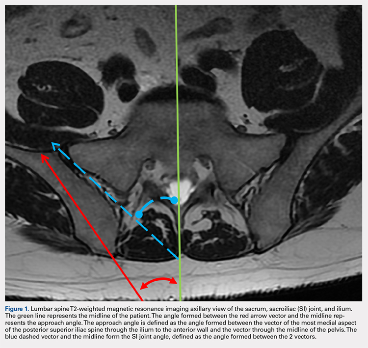
Continue to: For the 13 males, the mean SI joint...
RESULTS
The results are reported in the Table.
Table. Measurements of Patients Taken on Axial T2-Weighted Views of Lumbosacral MRI Scansa
Patient | SI Joint Angle (°) | Approach Angle (°) | PSIS Table Width (cm) | PSIS to Anterior Ilium Wall (cm) | Perpendicular Distance PSIS to Anterior Joint (cm) | Post Ilium Wall to SI Joint Width (cm) |
Males | ||||||
1 | 28.80 | 19.50 | 1.24 | 8.80 | 4.16 | 1.52 |
2 | 31.80 | 27.60 | 1.70 | 7.89 | 3.49 | 1.02 |
3 | 33.70 | 27.70 | 1.12 | 8.14 | 3.15 | 1.28 |
4 | 23.70 | 26.40 | 0.95 | 6.66 | 3.22 | 0.65 |
5 | 35.90 | 28.40 | 0.84 | 7.60 | 2.57 | 0.95 |
6 | 33.80 | 29.30 | 1.20 | 7.73 | 2.34 | 0.90 |
7 | 30.30 | 21.20 | 1.36 | 8.44 | 3.95 | 1.18 |
8 | 34.50 | 20.40 | 1.53 | 7.08 | 3.98 | 1.56 |
9 | 28.70 | 24.00 | 1.34 | 8.19 | 3.51 | 1.31 |
10 | 22.40 | 20.10 | 1.37 | 7.30 | 3.87 | 1.28 |
11 | 33.60 | 20.80 | 0.88 | 6.43 | 3.26 | 0.94 |
12 | 48.50 | 31.00 | 1.15 | 6.69 | 2.97 | 1.38 |
13 | 20.20 | 20.90 | 0.94 | 6.95 | 3.79 | 1.05 |
Averages | 31.22 | 24.41 | 1.20 | 7.53 | 3.40 | 1.16 |
Standard Deviation | 7.18 | 4.11 | 0.26 | 0.75 | 0.56 | 0.26 |
Females | ||||||
14 | 22.80 | 23.20 | 1.54 | 7.21 | 3.45 | 1.39 |
15 | 33.30 | 21.40 | 1.09 | 7.26 | 3.57 | 0.98 |
16 | 19.70 | 15.60 | 0.78 | 8.32 | 3.76 | 0.86 |
17 | 17.50 | 15.60 | 0.61 | 7.57 | 3.37 | 1.03 |
18 | 48.20 | 26.60 | 0.94 | 6.62 | 3.16 | 0.71 |
19 | 38.20 | 28.30 | 0.90 | 6.32 | 2.23 | 0.91 |
20 | 44.50 | 31.70 | 0.99 | 6.19 | 3.06 | 0.76 |
21 | 24.10 | 18.00 | 0.92 | 6.99 | 3.23 | 0.71 |
22 | 17.20 | 14.80 | 0.81 | 6.00 | 2.81 | 1.13 |
23 | 42.00 | 38.50 | 1.00 | 5.33 | 2.47 | 1.42 |
24 | 32.00 | 25.50 | 0.98 | 6.01 | 2.79 | 1.21 |
25 | 24.70 | 24.80 | 0.87 | 6.09 | 2.79 | 1.02 |
26 | 19.80 | 22.30 | 1.04 | 7.71 | 2.37 | 1.36 |
Averages | 29.54 | 23.56 | 0.96 | 6.74 | 3.00 | 1.04 |
Standard Deviation | 10.84 | 6.88 | 0.21 | 0.85 | 0.48 | 0.25 |
All patients Averages | 30.38 | 23.98 | 1.08 | 7.14 | 3.20 | 1.10 |
Standard Deviation | 9.05 | 5.57 | 0.26 | 0.88 | 0.55 | 0.26 |
aStatistical significance is denoted as P < .02.
Abbreviations: MRI, magnetic resonance imaging; PSIS, posterior iliac spine; SI, sacroiliac.
For the 13 males, the mean SI joint angle was 31.22° ± 7.18° (range, 20.20° to 48.50°). The mean approach angle was 24.41° ± 4.11° (range, 19.50° to 31.00°). The mean PSIS table width was 1.20 cm ± 0.26 cm (range, 0.84 cm to 1.70 cm). The mean distance from the PSIS to the anterior ilium wall was 7.53 cm ± 0.75 cm (range, 6.43 cm to 8.80 cm). The mean perpendicular distance from the PSIS table to the anterior ilium was 3.40 cm ± 0.56 cm (range, 2.34 cm to 4.16 cm). The mean minimum width of the ilium to the SI joint was 1.16 cm ± 0.26 cm (range, 0.65 cm to 1.56 cm).
For the 13 females, the mean SI joint angle was 29.54° ± 10.84° (range, 17.20° to 48.20°). The mean approach angle was 23.56° ± 6.88° (range, 14.80° to 38.50°). The mean PSIS table width was 0.96 cm ± 0.21 cm (range, 0.61 cm to 1.54 cm). The mean distance from the PSIS to the anterior ilium wall was 6.74 cm ± 0.85 cm (range, 5.33 cm to 8.32 cm). The mean perpendicular distance from the PSIS table to the anterior ilium was 3.00 cm ± 0.48 cm (range, 2.23 cm to 3.76 cm). The mean minimum width of the ilium to the SI joint was 1.04 cm ± 0.25 cm (range, 0.71 cm to 1.42 cm).
For the 26 total patients, the mean SI joint angle was 30.38° ± 9.05° (range, 17.20° to 48.50°). The mean approach angle was 23.98° ± 5.57° (range, 14.80° to 38.50°). The mean PSIS table width was 1.08 cm ± 0.26 cm (range, 0.61 cm to 1.70 cm). The mean distance from the PSIS to the anterior ilium wall was 7.14 cm ± 0.88 cm (range, 5.33 cm to 8.80 cm). The mean perpendicular distance from the PSIS table to the anterior ilium was 3.20 cm ± 0.55 cm (range, 2.23 cm to 4.16 cm). The mean minimum width of the ilium to the SI joint was 1.10 cm ± 0.26 cm (range, 0.65 cm to 1.56 cm).
There was a statistically significant difference between the male and female groups for the maximum distance the trocar can be advanced from the PSIS to the anterior ilium wall (P < .02), and a statistically significant difference for the PSIS table width (P < .02). There were no significant differences between the male and female groups for the approach angle, the SI joint angle, the perpendicular distance from the PSIS to the anterior ilium, and the minimum width of the ilium to the SI joint.
Continue to: The patient is brought to the procedure...
TECHNIQUE: ILIAC CREST (PSIS) BONE MARROW ASPIRATION
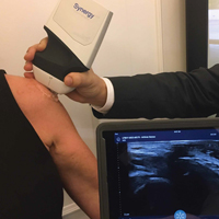
The patient is brought to the procedure room and placed in a prone position. The donor site is prepared and draped in the usual sterile manner. Ultrasound is used to identify the median sacral crest in a short-axis view. The probe is then moved laterally to identify the PSIS (Figures 4A, 4B). 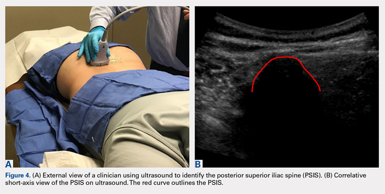
The crosshairs on the ultrasound probe are used to mark the center lines of each plane. The central point marks the location of the PSIS. Alternatively, an in-plane technique can be used to place a spinal needle on the exact entry point on the PSIS. Once the PSIS and entry point are identified, the site is blocked with 10 mL of 0.5% ropivacaine.
Prior to introduction of the trocar, all instrumentation is primed with heparin and syringes are prepped with anticoagulant citrate dextrose solution, solution A. A stab incision is made at the site. The trocar is placed at the entry point, which should be centered in a superior-inferior plane and at the most medial point of the PSIS. Starting with the trocar vertical, the trocar is angled laterally 24° by dropping the hand medially toward the midline. No angulation cephalad or caudad is necessary, but cephalad must be avoided so as not to skive superiorly. This angle, which is recommended for both males and females, allows for the greatest distance the trocar can travel in bone before hitting the anterior ilium wall. A standard deviation of 5.57° is present, which should be considered. Steady pressure should be applied with a slight twisting motion on the PSIS. If advancement of the trocar is too difficult, a mallet or drill can be used to assist in penetration.
With the trocar advanced into the bone 1 cm, the trocar needle is removed while the cannula remains in place. The syringe is attached to the top of the cannula. The syringe plunger is pulled back to aspirate 20 mL of bone marrow. The cannula and syringe assembly are advanced 2 cm farther into the bone to allow for aspiration of a new location within the bone marrow cavity, and 20 mL of bone marrow are again aspirated. This is done a final time, advancing the trocar another 2 cm and aspirating a final 20 mL of bone marrow. The entire process should yield roughly 60 mL of bone marrow from one side. If desired, the same process can be repeated for the contralateral PSIS to yield a total of 120 mL of bone marrow from the 2 sites.
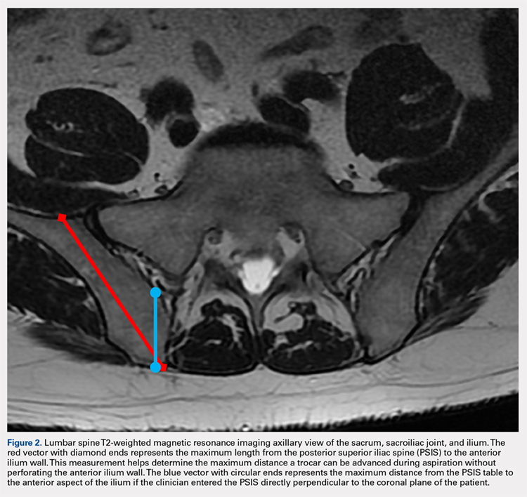
Based on our data, the average distance to the anterior ilium wall was 7 cm, but the shortest distance noted in this study was 5 cm. On the basis of the data presented, this technique allows for safe advancement based on even the shortest measured distance, without fear of puncturing the anterior ilium wall. Perforation could damage the femoral nerve and the internal or external iliac artery or vein that lie anterior to the ilium.
Continue to: We hypothesized that there...
DISCUSSION
We hypothesized that there would be an optimal angle of entry and maximal safe distance the trocar could advance through the ilium when aspirating. Because male and female pelvic anatomy differs, we also hypothesized that there would be differences in distance and size measurements for males and females. Our results supported our hypothesis that there is an ideal approach angle. The results also showed that the maximum distance the trocar can advance and the width of the PSIS table differ significantly between males and females.
Although pelvic anatomy differs between males and females, there should be an ideal entry angle that would allow maximum advancement into the ilium without perforating the anterior wall, which we defined as the approach angle. In our comparison of 26 MRI scans, we found that the approach angle did not differ significantly between the 2 groups (13 males, 13 females). This allows clinicians to enter the PSIS at roughly 24° medial to the parasagittal line, maximizing the space before puncturing into the anterior pelvis in either males or females.
If clinicians were to enter perpendicular to the patient’s PSIS, they would, on average, be able to advance only 3.20 cm before encountering the SI joint. When entering at 24° as we recommend, the average distance increases to 7.14 cm. Although the angle did not differ significantly, there was a significant difference between males and females in the length from the PSIS to the anterior wall, with males having 7.53 cm distance and females 6.74 cm. This is an important measurement because if the anterior ilium wall is punctured, the femoral nerve and the common, internal and external iliac arteries and veins could be damaged, resulting in retroperitoneal hemorrhage.
A fatality in 2001 in the United Kingdom led to a national audit of bone marrow aspiration and biopsies.4-6 Although these procedures were done primarily for patients with cancer, hemorrhagic events were the most frequent and serious events. This audit led to the identification of many risk factors. Bain4-6 conducted reviews of bone marrow aspirations and biopsies in the United Kingdom from 2002 to 2004. Of a total of 53,088 procedures conducted during that time frame, 48 (0.09%) adverse events occurred, with 29 (0.05%) being hemorrhagic events. Although infrequent, hemorrhagic adverse events represent significant morbidity. Reviews such as those conducted by Bain4-6 highlight the importance of a study that helps determine the optimal parameters for aspiration to ensure safety and reliability.
Hernigou and colleagues2,3 conducted studies analyzing different “sectors” in an attempt to develop a safe aspiration technique. They found that obese patients were at higher risk, and some sites of aspiration (sectors 1, 4, 5) had increased risk for perforation and damage to surrounding structures. Their sector 6, which incorporated the entirety of the PSIS table, was considered the safest, most reliable site for trocar introduction.2,3 Hernigou and colleagues,2 in comparing the bone mass of the sectors, also noted that sector 6 has the greatest bone thickness close to the entry point, making it the most favorable site. The PSIS is not just a point; it is more a “table.” The PSIS can be palpated posteriorly, but this is inaccurate and unreliable, particularly in larger individuals. The PSIS table can be identified on ultrasound before introducing the trocar, which is a more reliable method of landmark identification than palpation guidance, just as in ultrasound-guided injections7-16 and procedures.9,12,17-19
Continue to: If the PSIS is not accurately...
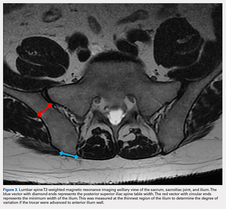
If the PSIS is not accurately identified, penetration laterally will result in entering the ilium wing, where it is quite narrow. We found the distance between the posterior ilium wall and the SI joint to be only 1.10 cm wide (Figure 3); we defined this area as the narrow corridor. Superior and lateral entry could damage the superior cluneal nerves coming over the iliac crest, which are located 6 cm lateral to the SI joint. Inferior and lateral entry 6 cm below the PSIS could reach the greater sciatic foramen, damaging the sacral plexus and superior gluteal artery and vein. If the entry slips above the PSIS over the pelvis, the trocar could enter the retroperitoneal space and damage the femoral nerve and common iliac artery and vein, leading to a retroperitoneal hemorrhage.4-6,20
MSCs are found as perivascular cells and lie in the cortices of bones.21 Following the approach angle and directed line from the PSIS to the anterior ilium wall described in this study (Figures 1 and 2), the trocar would pass through the narrow corridor as it advances farther into the ilium. The minimum width of this corridor was measured in this study and, on average, was 1.10 cm wide from cortex to cortex (Figure 3). As the bone marrow is aspirated from this narrow corridor, the clinician is gathering MSCs from both the lateral and medial cortices of the ilium. By aspirating from a greater surface area of the cortices, it is believed that this will increase the total collection of MSCs.
CONCLUSION
Although there are reports in the literature that describe techniques for bone marrow aspiration from the iliac crest, the techniques are very general and vague regarding the ideal angles and methods. Studies have attempted to quantify the safest entry sites for aspiration but have not detailed ideal parameters for collection. Blind aspiration from the iliac crest can have serious implications if adverse events occur, and thus there is a need for a safe and reliable method of aspiration from the iliac crest. Ultrasound guidance to identify anatomy, as opposed to palpation guidance, ensures anatomic placement of the trocar while minimizing the risk of aspiration. Based on the measurements gathered in this study, an optimal angle of entry and safe distance of penetration have been identified. Using our data and relevant literature, we developed a technique for a safe, consistent, and reliable method of bone marrow aspiration out of the iliac crest.
1. Chahla J, Mannava S, Cinque ME, Geeslin AG, Codina D, LaPrade RF. Bone marrow aspirate concentrate harvesting and processing technique. Arthrosc Tech. 2017;6(2):e441-e445. doi:10.1016/j.eats.2016.10.024.
2. Hernigou J, Alves A, Homma Y, Guissou I, Hernigou P. Anatomy of the ilium for bone marrow aspiration: map of sectors and implication for safe trocar placement. Int Orthop. 2014;38(12):2585-2590. doi:10.1007/s00264-014-2353-7.
3. Hernigou J, Picard L, Alves A, Silvera J, Homma Y, Hernigou P. Understanding bone safety zones during bone marrow aspiration from the iliac crest: the sector rule. Int Orthop. 2014;38(11):2377-2384. doi:10.1007/s00264-014-2343-9.
4. Bain BJ. Bone marrow biopsy morbidity: review of 2003. J Clin Pathol. 2005;58(4):406-408. doi:10.1136/jcp.2004.022178.
5. Bain BJ. Bone marrow biopsy morbidity and mortality: 2002 data. Clin Lab Haematol. 2004;26(5):315-318. doi:10.1111/j.1365-2257.2004.00630.x.
6. Bain BJ. Morbidity associated with bone marrow aspiration and trephine biopsy - a review of UK data for 2004. Haematologica. 2006;91(9):1293-1294.
7. Berkoff DJ, Miller LE, Block JE. Clinical utility of ultrasound guidance for intra-articular knee injections: a review. Clin Interv Aging. 2012;7:89-95. doi:10.2147/CIA.S29265.
8. Henkus HE, Cobben LP, Coerkamp EG, Nelissen RG, van Arkel ER. The accuracy of subacromial injections: a prospective randomized magnetic resonance imaging study. Arthroscopy. 2006;22(3):277-282. doi:10.1016/j.arthro.2005.12.019.
9. Hirahara AM, Panero AJ. A guide to ultrasound of the shoulder, part 3: interventional and procedural uses. Am J Orthop. 2016;45(7):440-445.
10. Jackson DW, Evans NA, Thomas BM. Accuracy of needle placement into the intra-articular space of the knee. J Bone Joint Surg Am. 2002;84-A(9):1522-1527.
11. Naredo E, Cabero F, Beneyto P, et al. A randomized comparative study of short term response to blind versus sonographic-guided injection of local corticosteroids in patients with painful shoulder. J Rheumatol. 2004;31(2):308-314.
12. Panero AJ, Hirahara AM. A guide to ultrasound of the shoulder, part 2: the diagnostic evaluation. Am J Orthop. 2016;45(4):233-238.
13. Sethi PM, El Attrache N. Accuracy of intra-articular injection of the glenohumeral joint: a cadaveric study. Orthopedics. 2006;29(2):149-152.
14. Sibbit WL Jr, Peisajovich A, Michael AA, et al. Does sonographic needle guidance affect the clinical outcome of intraarticular injections? J Rheumatol. 2009;36(9):1892-1902. doi:10.3899/jrheum.090013.
15. Smith J, Brault JS, Rizzo M, Sayeed YA, Finnoff JT. Accuracy of sonographically guided and palpation guided scaphotrapeziotrapezoid joint injections. J Ultrasound Med. 2011;30(11):1509-1515. doi:10.7863/jum.2011.30.11.1509.
16. Yamakado K. The targeting accuracy of subacromial injection to the shoulder: an arthrographic evaluation. Arthroscopy. 2002;18(8):887-891.
17. Hirahara AM, Andersen WJ. Ultrasound-guided percutaneous reconstruction of the anterolateral ligament: surgical technique and case report. Am J Orthop. 2016;45(7):418-422, 460.
18. Hirahara AM, Andersen WJ. Ultrasound-guided percutaneous repair of medial patellofemoral ligament: surgical technique and outcomes. Am J Orthop. 2017;46(3):152-157.
19. Hirahara AM, Mackay G, Andersen WJ. Ultrasound-guided InternalBrace of the medial collateral ligament. Arthrosc Tech. Submitted.
20. Jamaludin WFW, Mukari SAM, Wahid SFA. Retroperitoneal hemorrhage associated with bone marrow trephine biopsy. Am J Case Rep. 2013;14:489-493. doi:10.12659/AJCR.889274.
21. Bianco P, Cao X, Frenette PS, et al. The meaning, the sense and the significance: translating the science of mesenchymal stem cells into medicine. Nat Med. 2013;19(1):35-42. doi:10.1038/nm.3028.
ABSTRACT
Use of mesenchymal stem cells from bone marrow has gained significant popularity. The iliac crest has been determined to be an effective site for harvesting mesenchymal stem cells. Review of the literature reveals that multiple techniques are used to harvest bone marrow aspirate from the iliac crest, but the descriptions are based on the experience of various authors as opposed to studied anatomy. A safe, reliable, and reproducible method for aspiration has yet to be studied and described. We hypothesized that there would be an ideal angle and distance for aspiration that would be the safest, most consistent, and most reliable. Using magnetic resonance imaging (MRI), we reviewed 26 total lumbar spine MRI scans (13 males, 13 females) and found that an angle of 24° should be used when entering the most medial aspect of the posterior superior iliac spine (PSIS) and that this angle did not differ between the sexes. The distance that the trocar can advance after entry before hitting the anterior ilium wall varied significantly between males and females, being 7.53 cm in males and 6.74 cm in females. In addition, the size of the PSIS table was significantly different between males and females (1.20 cm and 0.96 cm, respectively). No other significant differences in the measurements gathered were found. Using the data gleaned from this study, we developed an aspiration technique. This method uses ultrasound to determine the location of the PSIS and the entry point on the PSIS. This contrasts with most techniques that use landmark palpation, which is known to be unreliable and inaccurate. The described technique for aspiration from the PSIS is safe, reliable, reproducible, and substantiated by data.
The iliac crest is an effective site for harvesting bone marrow stem cells. It allows for easy access and is superficial in most individuals, allowing for a relatively quick and simple procedure. Use of mesenchymal stem cells (MSCs) for treatment of orthopedic injuries has grown recently. Whereas overall use has increased, review of the literature reveals very few techniques for iliac crest aspiration,1 but these are not based on anatomic relationships or studies. Hernigou and colleagues2,3 attempted to quantitatively evaluate potential “sectors” allowing for safe aspiration using cadaver and computed tomographic reconstruction imaging. We used magnetic resonance imaging (MRI) to analyze aspiration parameters. Owing to the ilium’s anatomy, improper positioning or aspiration technique during aspiration can result in serious injury.2,4-6 We hypothesized that there is an ideal angle and positioning for bone marrow aspiration from the posterior superior iliac spine (PSIS) that is safe, consistent, and reproducible. Although most aspiration techniques use landmark palpation, this is unreliable and inaccurate, especially when compared with ultrasound-guided injections7-16 and procedures.9,12,17-19 We describe our technique using ultrasound to visualize patient anatomy and accurately determine anatomic entry with the trocar.
METHODS
MRI scans of 26 patients (13 males, 13 females) were reviewed to determine average angles and distances. Axial T2-weighted views of the lumbar spine were used in all analyses. The sacroiliac (SI) joint angle was defined as the angle formed between the vector through the midline of the pelvis and the vector that is parallel to the SI joint. The approach angle was defined as the angle formed between the vector of the most medial aspect of the PSIS through the ilium to the anterior wall and the vector through the midline of the pelvis (Figure 1).
Continue to: For the 13 males, the mean SI joint...
RESULTS
The results are reported in the Table.
Table. Measurements of Patients Taken on Axial T2-Weighted Views of Lumbosacral MRI Scansa
Patient | SI Joint Angle (°) | Approach Angle (°) | PSIS Table Width (cm) | PSIS to Anterior Ilium Wall (cm) | Perpendicular Distance PSIS to Anterior Joint (cm) | Post Ilium Wall to SI Joint Width (cm) |
Males | ||||||
1 | 28.80 | 19.50 | 1.24 | 8.80 | 4.16 | 1.52 |
2 | 31.80 | 27.60 | 1.70 | 7.89 | 3.49 | 1.02 |
3 | 33.70 | 27.70 | 1.12 | 8.14 | 3.15 | 1.28 |
4 | 23.70 | 26.40 | 0.95 | 6.66 | 3.22 | 0.65 |
5 | 35.90 | 28.40 | 0.84 | 7.60 | 2.57 | 0.95 |
6 | 33.80 | 29.30 | 1.20 | 7.73 | 2.34 | 0.90 |
7 | 30.30 | 21.20 | 1.36 | 8.44 | 3.95 | 1.18 |
8 | 34.50 | 20.40 | 1.53 | 7.08 | 3.98 | 1.56 |
9 | 28.70 | 24.00 | 1.34 | 8.19 | 3.51 | 1.31 |
10 | 22.40 | 20.10 | 1.37 | 7.30 | 3.87 | 1.28 |
11 | 33.60 | 20.80 | 0.88 | 6.43 | 3.26 | 0.94 |
12 | 48.50 | 31.00 | 1.15 | 6.69 | 2.97 | 1.38 |
13 | 20.20 | 20.90 | 0.94 | 6.95 | 3.79 | 1.05 |
Averages | 31.22 | 24.41 | 1.20 | 7.53 | 3.40 | 1.16 |
Standard Deviation | 7.18 | 4.11 | 0.26 | 0.75 | 0.56 | 0.26 |
Females | ||||||
14 | 22.80 | 23.20 | 1.54 | 7.21 | 3.45 | 1.39 |
15 | 33.30 | 21.40 | 1.09 | 7.26 | 3.57 | 0.98 |
16 | 19.70 | 15.60 | 0.78 | 8.32 | 3.76 | 0.86 |
17 | 17.50 | 15.60 | 0.61 | 7.57 | 3.37 | 1.03 |
18 | 48.20 | 26.60 | 0.94 | 6.62 | 3.16 | 0.71 |
19 | 38.20 | 28.30 | 0.90 | 6.32 | 2.23 | 0.91 |
20 | 44.50 | 31.70 | 0.99 | 6.19 | 3.06 | 0.76 |
21 | 24.10 | 18.00 | 0.92 | 6.99 | 3.23 | 0.71 |
22 | 17.20 | 14.80 | 0.81 | 6.00 | 2.81 | 1.13 |
23 | 42.00 | 38.50 | 1.00 | 5.33 | 2.47 | 1.42 |
24 | 32.00 | 25.50 | 0.98 | 6.01 | 2.79 | 1.21 |
25 | 24.70 | 24.80 | 0.87 | 6.09 | 2.79 | 1.02 |
26 | 19.80 | 22.30 | 1.04 | 7.71 | 2.37 | 1.36 |
Averages | 29.54 | 23.56 | 0.96 | 6.74 | 3.00 | 1.04 |
Standard Deviation | 10.84 | 6.88 | 0.21 | 0.85 | 0.48 | 0.25 |
All patients Averages | 30.38 | 23.98 | 1.08 | 7.14 | 3.20 | 1.10 |
Standard Deviation | 9.05 | 5.57 | 0.26 | 0.88 | 0.55 | 0.26 |
aStatistical significance is denoted as P < .02.
Abbreviations: MRI, magnetic resonance imaging; PSIS, posterior iliac spine; SI, sacroiliac.
For the 13 males, the mean SI joint angle was 31.22° ± 7.18° (range, 20.20° to 48.50°). The mean approach angle was 24.41° ± 4.11° (range, 19.50° to 31.00°). The mean PSIS table width was 1.20 cm ± 0.26 cm (range, 0.84 cm to 1.70 cm). The mean distance from the PSIS to the anterior ilium wall was 7.53 cm ± 0.75 cm (range, 6.43 cm to 8.80 cm). The mean perpendicular distance from the PSIS table to the anterior ilium was 3.40 cm ± 0.56 cm (range, 2.34 cm to 4.16 cm). The mean minimum width of the ilium to the SI joint was 1.16 cm ± 0.26 cm (range, 0.65 cm to 1.56 cm).
For the 13 females, the mean SI joint angle was 29.54° ± 10.84° (range, 17.20° to 48.20°). The mean approach angle was 23.56° ± 6.88° (range, 14.80° to 38.50°). The mean PSIS table width was 0.96 cm ± 0.21 cm (range, 0.61 cm to 1.54 cm). The mean distance from the PSIS to the anterior ilium wall was 6.74 cm ± 0.85 cm (range, 5.33 cm to 8.32 cm). The mean perpendicular distance from the PSIS table to the anterior ilium was 3.00 cm ± 0.48 cm (range, 2.23 cm to 3.76 cm). The mean minimum width of the ilium to the SI joint was 1.04 cm ± 0.25 cm (range, 0.71 cm to 1.42 cm).
For the 26 total patients, the mean SI joint angle was 30.38° ± 9.05° (range, 17.20° to 48.50°). The mean approach angle was 23.98° ± 5.57° (range, 14.80° to 38.50°). The mean PSIS table width was 1.08 cm ± 0.26 cm (range, 0.61 cm to 1.70 cm). The mean distance from the PSIS to the anterior ilium wall was 7.14 cm ± 0.88 cm (range, 5.33 cm to 8.80 cm). The mean perpendicular distance from the PSIS table to the anterior ilium was 3.20 cm ± 0.55 cm (range, 2.23 cm to 4.16 cm). The mean minimum width of the ilium to the SI joint was 1.10 cm ± 0.26 cm (range, 0.65 cm to 1.56 cm).
There was a statistically significant difference between the male and female groups for the maximum distance the trocar can be advanced from the PSIS to the anterior ilium wall (P < .02), and a statistically significant difference for the PSIS table width (P < .02). There were no significant differences between the male and female groups for the approach angle, the SI joint angle, the perpendicular distance from the PSIS to the anterior ilium, and the minimum width of the ilium to the SI joint.
Continue to: The patient is brought to the procedure...
TECHNIQUE: ILIAC CREST (PSIS) BONE MARROW ASPIRATION
The patient is brought to the procedure room and placed in a prone position. The donor site is prepared and draped in the usual sterile manner. Ultrasound is used to identify the median sacral crest in a short-axis view. The probe is then moved laterally to identify the PSIS (Figures 4A, 4B).
The crosshairs on the ultrasound probe are used to mark the center lines of each plane. The central point marks the location of the PSIS. Alternatively, an in-plane technique can be used to place a spinal needle on the exact entry point on the PSIS. Once the PSIS and entry point are identified, the site is blocked with 10 mL of 0.5% ropivacaine.
Prior to introduction of the trocar, all instrumentation is primed with heparin and syringes are prepped with anticoagulant citrate dextrose solution, solution A. A stab incision is made at the site. The trocar is placed at the entry point, which should be centered in a superior-inferior plane and at the most medial point of the PSIS. Starting with the trocar vertical, the trocar is angled laterally 24° by dropping the hand medially toward the midline. No angulation cephalad or caudad is necessary, but cephalad must be avoided so as not to skive superiorly. This angle, which is recommended for both males and females, allows for the greatest distance the trocar can travel in bone before hitting the anterior ilium wall. A standard deviation of 5.57° is present, which should be considered. Steady pressure should be applied with a slight twisting motion on the PSIS. If advancement of the trocar is too difficult, a mallet or drill can be used to assist in penetration.
With the trocar advanced into the bone 1 cm, the trocar needle is removed while the cannula remains in place. The syringe is attached to the top of the cannula. The syringe plunger is pulled back to aspirate 20 mL of bone marrow. The cannula and syringe assembly are advanced 2 cm farther into the bone to allow for aspiration of a new location within the bone marrow cavity, and 20 mL of bone marrow are again aspirated. This is done a final time, advancing the trocar another 2 cm and aspirating a final 20 mL of bone marrow. The entire process should yield roughly 60 mL of bone marrow from one side. If desired, the same process can be repeated for the contralateral PSIS to yield a total of 120 mL of bone marrow from the 2 sites.
Based on our data, the average distance to the anterior ilium wall was 7 cm, but the shortest distance noted in this study was 5 cm. On the basis of the data presented, this technique allows for safe advancement based on even the shortest measured distance, without fear of puncturing the anterior ilium wall. Perforation could damage the femoral nerve and the internal or external iliac artery or vein that lie anterior to the ilium.
Continue to: We hypothesized that there...
DISCUSSION
We hypothesized that there would be an optimal angle of entry and maximal safe distance the trocar could advance through the ilium when aspirating. Because male and female pelvic anatomy differs, we also hypothesized that there would be differences in distance and size measurements for males and females. Our results supported our hypothesis that there is an ideal approach angle. The results also showed that the maximum distance the trocar can advance and the width of the PSIS table differ significantly between males and females.
Although pelvic anatomy differs between males and females, there should be an ideal entry angle that would allow maximum advancement into the ilium without perforating the anterior wall, which we defined as the approach angle. In our comparison of 26 MRI scans, we found that the approach angle did not differ significantly between the 2 groups (13 males, 13 females). This allows clinicians to enter the PSIS at roughly 24° medial to the parasagittal line, maximizing the space before puncturing into the anterior pelvis in either males or females.
If clinicians were to enter perpendicular to the patient’s PSIS, they would, on average, be able to advance only 3.20 cm before encountering the SI joint. When entering at 24° as we recommend, the average distance increases to 7.14 cm. Although the angle did not differ significantly, there was a significant difference between males and females in the length from the PSIS to the anterior wall, with males having 7.53 cm distance and females 6.74 cm. This is an important measurement because if the anterior ilium wall is punctured, the femoral nerve and the common, internal and external iliac arteries and veins could be damaged, resulting in retroperitoneal hemorrhage.
A fatality in 2001 in the United Kingdom led to a national audit of bone marrow aspiration and biopsies.4-6 Although these procedures were done primarily for patients with cancer, hemorrhagic events were the most frequent and serious events. This audit led to the identification of many risk factors. Bain4-6 conducted reviews of bone marrow aspirations and biopsies in the United Kingdom from 2002 to 2004. Of a total of 53,088 procedures conducted during that time frame, 48 (0.09%) adverse events occurred, with 29 (0.05%) being hemorrhagic events. Although infrequent, hemorrhagic adverse events represent significant morbidity. Reviews such as those conducted by Bain4-6 highlight the importance of a study that helps determine the optimal parameters for aspiration to ensure safety and reliability.
Hernigou and colleagues2,3 conducted studies analyzing different “sectors” in an attempt to develop a safe aspiration technique. They found that obese patients were at higher risk, and some sites of aspiration (sectors 1, 4, 5) had increased risk for perforation and damage to surrounding structures. Their sector 6, which incorporated the entirety of the PSIS table, was considered the safest, most reliable site for trocar introduction.2,3 Hernigou and colleagues,2 in comparing the bone mass of the sectors, also noted that sector 6 has the greatest bone thickness close to the entry point, making it the most favorable site. The PSIS is not just a point; it is more a “table.” The PSIS can be palpated posteriorly, but this is inaccurate and unreliable, particularly in larger individuals. The PSIS table can be identified on ultrasound before introducing the trocar, which is a more reliable method of landmark identification than palpation guidance, just as in ultrasound-guided injections7-16 and procedures.9,12,17-19
Continue to: If the PSIS is not accurately...
If the PSIS is not accurately identified, penetration laterally will result in entering the ilium wing, where it is quite narrow. We found the distance between the posterior ilium wall and the SI joint to be only 1.10 cm wide (Figure 3); we defined this area as the narrow corridor. Superior and lateral entry could damage the superior cluneal nerves coming over the iliac crest, which are located 6 cm lateral to the SI joint. Inferior and lateral entry 6 cm below the PSIS could reach the greater sciatic foramen, damaging the sacral plexus and superior gluteal artery and vein. If the entry slips above the PSIS over the pelvis, the trocar could enter the retroperitoneal space and damage the femoral nerve and common iliac artery and vein, leading to a retroperitoneal hemorrhage.4-6,20
MSCs are found as perivascular cells and lie in the cortices of bones.21 Following the approach angle and directed line from the PSIS to the anterior ilium wall described in this study (Figures 1 and 2), the trocar would pass through the narrow corridor as it advances farther into the ilium. The minimum width of this corridor was measured in this study and, on average, was 1.10 cm wide from cortex to cortex (Figure 3). As the bone marrow is aspirated from this narrow corridor, the clinician is gathering MSCs from both the lateral and medial cortices of the ilium. By aspirating from a greater surface area of the cortices, it is believed that this will increase the total collection of MSCs.
CONCLUSION
Although there are reports in the literature that describe techniques for bone marrow aspiration from the iliac crest, the techniques are very general and vague regarding the ideal angles and methods. Studies have attempted to quantify the safest entry sites for aspiration but have not detailed ideal parameters for collection. Blind aspiration from the iliac crest can have serious implications if adverse events occur, and thus there is a need for a safe and reliable method of aspiration from the iliac crest. Ultrasound guidance to identify anatomy, as opposed to palpation guidance, ensures anatomic placement of the trocar while minimizing the risk of aspiration. Based on the measurements gathered in this study, an optimal angle of entry and safe distance of penetration have been identified. Using our data and relevant literature, we developed a technique for a safe, consistent, and reliable method of bone marrow aspiration out of the iliac crest.
1. Chahla J, Mannava S, Cinque ME, Geeslin AG, Codina D, LaPrade RF. Bone marrow aspirate concentrate harvesting and processing technique. Arthrosc Tech. 2017;6(2):e441-e445. doi:10.1016/j.eats.2016.10.024.
2. Hernigou J, Alves A, Homma Y, Guissou I, Hernigou P. Anatomy of the ilium for bone marrow aspiration: map of sectors and implication for safe trocar placement. Int Orthop. 2014;38(12):2585-2590. doi:10.1007/s00264-014-2353-7.
3. Hernigou J, Picard L, Alves A, Silvera J, Homma Y, Hernigou P. Understanding bone safety zones during bone marrow aspiration from the iliac crest: the sector rule. Int Orthop. 2014;38(11):2377-2384. doi:10.1007/s00264-014-2343-9.
4. Bain BJ. Bone marrow biopsy morbidity: review of 2003. J Clin Pathol. 2005;58(4):406-408. doi:10.1136/jcp.2004.022178.
5. Bain BJ. Bone marrow biopsy morbidity and mortality: 2002 data. Clin Lab Haematol. 2004;26(5):315-318. doi:10.1111/j.1365-2257.2004.00630.x.
6. Bain BJ. Morbidity associated with bone marrow aspiration and trephine biopsy - a review of UK data for 2004. Haematologica. 2006;91(9):1293-1294.
7. Berkoff DJ, Miller LE, Block JE. Clinical utility of ultrasound guidance for intra-articular knee injections: a review. Clin Interv Aging. 2012;7:89-95. doi:10.2147/CIA.S29265.
8. Henkus HE, Cobben LP, Coerkamp EG, Nelissen RG, van Arkel ER. The accuracy of subacromial injections: a prospective randomized magnetic resonance imaging study. Arthroscopy. 2006;22(3):277-282. doi:10.1016/j.arthro.2005.12.019.
9. Hirahara AM, Panero AJ. A guide to ultrasound of the shoulder, part 3: interventional and procedural uses. Am J Orthop. 2016;45(7):440-445.
10. Jackson DW, Evans NA, Thomas BM. Accuracy of needle placement into the intra-articular space of the knee. J Bone Joint Surg Am. 2002;84-A(9):1522-1527.
11. Naredo E, Cabero F, Beneyto P, et al. A randomized comparative study of short term response to blind versus sonographic-guided injection of local corticosteroids in patients with painful shoulder. J Rheumatol. 2004;31(2):308-314.
12. Panero AJ, Hirahara AM. A guide to ultrasound of the shoulder, part 2: the diagnostic evaluation. Am J Orthop. 2016;45(4):233-238.
13. Sethi PM, El Attrache N. Accuracy of intra-articular injection of the glenohumeral joint: a cadaveric study. Orthopedics. 2006;29(2):149-152.
14. Sibbit WL Jr, Peisajovich A, Michael AA, et al. Does sonographic needle guidance affect the clinical outcome of intraarticular injections? J Rheumatol. 2009;36(9):1892-1902. doi:10.3899/jrheum.090013.
15. Smith J, Brault JS, Rizzo M, Sayeed YA, Finnoff JT. Accuracy of sonographically guided and palpation guided scaphotrapeziotrapezoid joint injections. J Ultrasound Med. 2011;30(11):1509-1515. doi:10.7863/jum.2011.30.11.1509.
16. Yamakado K. The targeting accuracy of subacromial injection to the shoulder: an arthrographic evaluation. Arthroscopy. 2002;18(8):887-891.
17. Hirahara AM, Andersen WJ. Ultrasound-guided percutaneous reconstruction of the anterolateral ligament: surgical technique and case report. Am J Orthop. 2016;45(7):418-422, 460.
18. Hirahara AM, Andersen WJ. Ultrasound-guided percutaneous repair of medial patellofemoral ligament: surgical technique and outcomes. Am J Orthop. 2017;46(3):152-157.
19. Hirahara AM, Mackay G, Andersen WJ. Ultrasound-guided InternalBrace of the medial collateral ligament. Arthrosc Tech. Submitted.
20. Jamaludin WFW, Mukari SAM, Wahid SFA. Retroperitoneal hemorrhage associated with bone marrow trephine biopsy. Am J Case Rep. 2013;14:489-493. doi:10.12659/AJCR.889274.
21. Bianco P, Cao X, Frenette PS, et al. The meaning, the sense and the significance: translating the science of mesenchymal stem cells into medicine. Nat Med. 2013;19(1):35-42. doi:10.1038/nm.3028.
TAKE-HOME POINTS
- There is an ideal angle and distance for optimization of a bone marrow harvest from the iliac crest.
- Ultrasound is a reliable technology that allows clinicians to accurately and consistently identify the PSIS and avoid neurovascular structures.
- This safe, reliable bone marrow aspiration technique can lower the risk of serious potential complications.
- The ideal angle does not differ significantly between sexes, but the safe distance a clinician can advance does.
- The PSIS should be considered a “table” as opposed to a protuberance.
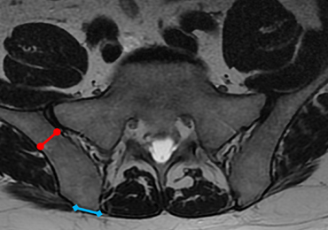
Superior Capsular Reconstruction: Clinical Outcomes After Minimum 2-Year Follow-Up
Take-Home Points
- The SCR is a viable treatment option for massive, irreparable RCTs.
- Arm position and exact measurement between anchors will help ensure proper graft tensioning.
- Anterior and posterior tension and margin convergence are critical to stabilizing the graft.
- Acromial-humeral distance, ASES, and VAS scores are improved and maintained over long-term follow-up.
- The dermal allograft should be 3.0 mm or thicker.
Conventional treatments for irreparable massive rotator cuff tears (RCTs) have ranged from nonoperative care to débridement and biceps tenotomy,1,2 partial cuff repair,3,4 bridging patch grafts,5 tendon transfers,6,7 and reverse total shoulder arthroplasty (RTSA).8,9 Superior capsular reconstruction (SCR), originally described by Mihata and colleagues,10 has been developed as an alternative to these interventions. Dr. Hirahara modified the technique to use dermal allograft instead of fascia lata autograft.10,11
Biomechanical analysis has confirmed the integral role of the superior capsule in shoulder function.10,12-14 In the presence of a massive RCT, the humeral head migrates superiorly, causing significant pain and functional deficits, such as pseudoparalysis. It is theorized that reestablishing this important stabilizer—centering the humeral head in the glenoid and allowing the larger muscles to move the arm about a proper fulcrum—improves function and decreases pain.
Using ultrasonography (US), radiography, magnetic resonance imaging (MRI), clinical outcome scores, and a visual analog scale (VAS) for pain, we prospectively evaluated minimum 2-year clinical outcomes of performing SCR with dermal allograft for irreparable RCTs.
Methods
Except where noted otherwise, all products mentioned in this section were made by Arthrex.
Surgical Technique
The surgical technique used here was described by Hirahara and Adams.11 ArthroFlex dermal allograft was attached to the greater tuberosity and the glenoid, creating a superior restraint that replaced the anatomical superior capsule (Figures 1A, 1B). Some cases included biceps tenotomy, subscapularis repair, or infraspinatus repair. 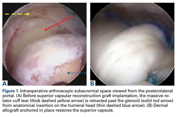
Medial fixation was obtained with a PASTA (partial articular supraspinatus tendon avulsion) bridge-type construct15 that consisted of two 3.0-mm BioComposite SutureTak anchors (placed medially on the glenoid rim, medial to the labrum) and a 3.5-mm BioComposite Vented SwiveLock. In some cases, a significant amount of tissue was present medially, and the third anchor was not used; instead, a double surgeon knot was used to fixate the double pulley medially.
Posterior margin convergence (PMC) was performed in all cases. Anterior margin convergence (AMC) was performed in only 3 cases.
Clinical Evaluation
All patients who underwent SCR were followed prospectively, and all signed an informed consent form. Between 2014 and the time of this study, 9 patients had surgery with a minimum 2-year follow-up. Before surgery, all patients received a diagnosis of full-thickness RCT with decreased acromial-humeral distance (AHD). One patient had RTSA 18 months after surgery, did not reach the 2-year follow-up, and was excluded from the data analysis. Patients were clinically evaluated on the 100-point American Shoulder and Elbow Surgeons (ASES) shoulder index and on a 10-point VAS for pain—before surgery, monthly for the first 6 months after surgery, then every 6 months until 2 years after surgery, and yearly thereafter. These patients were compared with Dr. Hirahara’s historical control patients, who had undergone repair of massive RCTs. Mean graft size was calculated and reported. Cases were separated and analyzed on the basis of whether AMC was performed. Student t tests were used to determine statistical differences between study patients’ preoperative and postoperative scores, between study and historical control patients, and between patients who had AMC performed and those who did not (P < .05).
Imaging
For all SCR patients, preoperative and postoperative radiographs were obtained in 2 planes: anterior-posterior with arm in neutral rotation, and scapular Y. On anteroposterior radiographs, AHD was measured from the most proximal aspect of the humeral head in a vertical line to the most inferior portion of the acromion (Figures 2A, 2B). 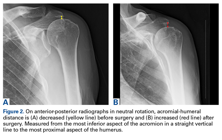
Results
The Table provides an overview of the study results. Eight patients (6 men, 2 women) met the final inclusion criteria for postoperative ASES and VAS data analysis. 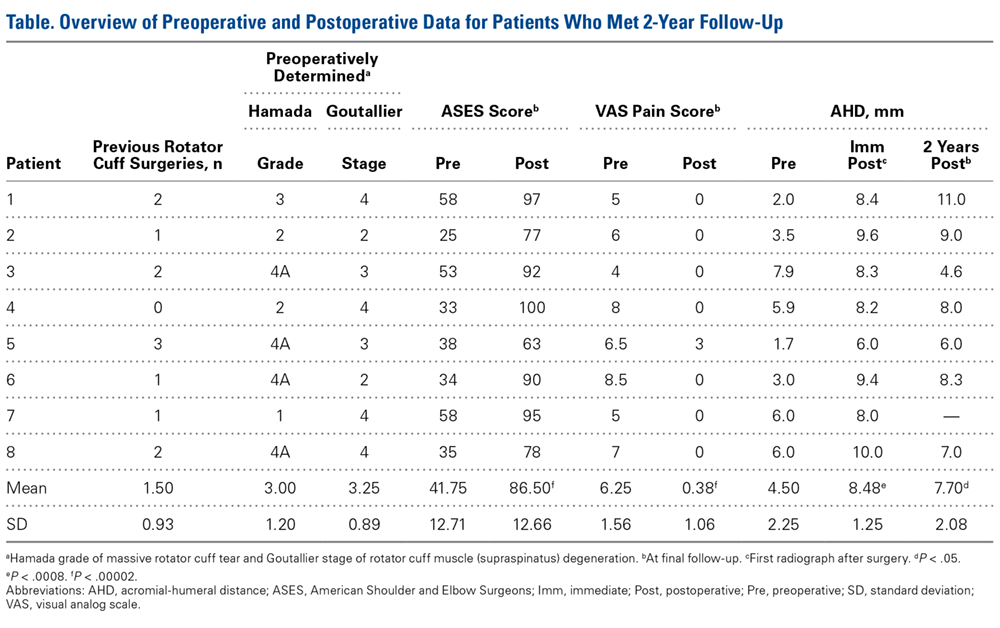
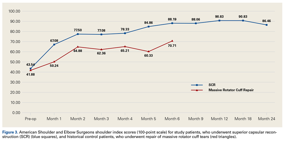
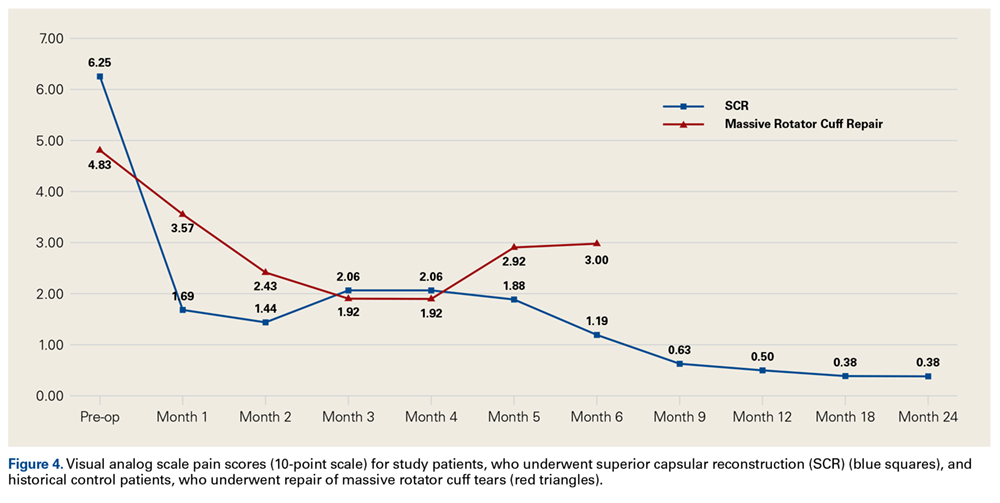
AHD was measured on a standard anteroposterior radiograph in neutral rotation. The Hamada grading scale16 was used to classify the massive RCTs before and after surgery. Before surgery, 4 were grade 4A, 1 grade 3, 2 grade 2, and 1 grade 1; immediately after surgery, all were grade 1 (AHD, ≥6 mm). Two years after surgery, 1 patient had an AHD of 4.6 mm after a failure caused by a fall. Mean (SD) preoperative AHD was 4.50 (2.25) mm (range, 1.7-7.9 mm). Radiographs obtained immediately (mean, 1.22 months; range, 1 day-2.73 months) after surgery showed AHD was significantly (P < .0008) increased (mean, 8.48 mm; SD, 1.25 mm; range, 6.0-10.0 mm) (Figure 5). 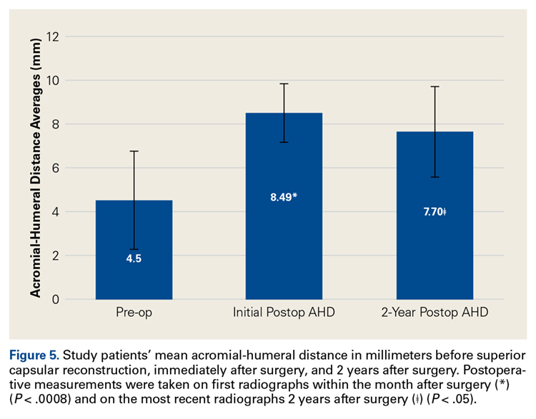
Mean graft size was 2.9 mm medial × 3.6 mm lateral × 5.4 mm anterior × 5.4 mm posterior. Three patients had AMC performed. There was a significant (P < .05) difference in ASES scores between patients who had AMC performed (93) and those who did not (77).
Ultrasonography
Two weeks to 2 months after surgery, all patients had an intact capsular graft and no pulsatile vessels on US. Between 4 months and 10 months, US showed the construct intact laterally in all cases, a pulsatile vessel in the graft at the tuberosity (evidence of blood flow) in 4 of 5 cases, and a pulsatile vessel hypertrophied in 2 cases (Figures 6A, 6B). 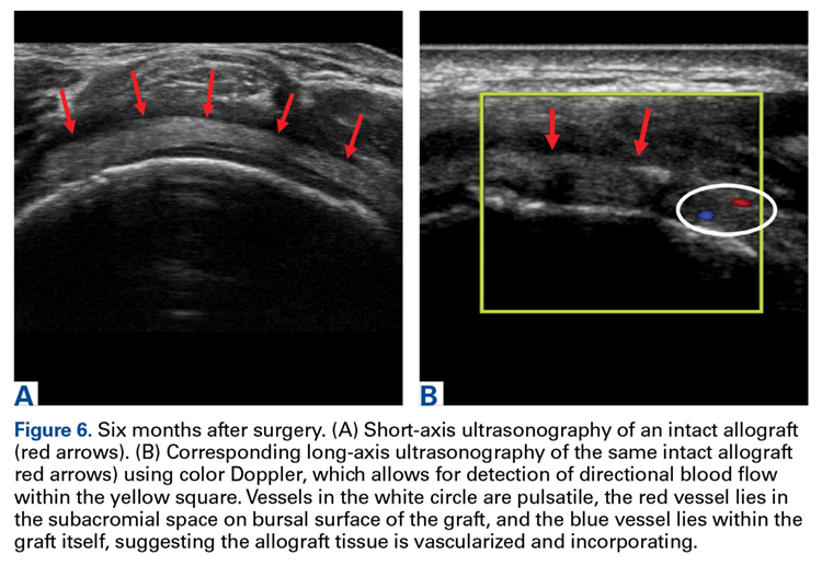
Magnetic Resonance Imaging
Before surgery, 4 patients had Goutallier17 stage 4 rotator cuff muscle degeneration, 2 had stage 3 degeneration, and 2 had stage 2 degeneration. Throughout the follow-up period, US was as effective as MRI in determining graft integrity, graft thickness, and greater tuberosity fixation. Therefore, the SCRs were assessed primarily with US. MRI was ordered only if a failure was suspected or if the patient had some form of trauma. A total of 7 MRIs were ordered for 5 of the 8 patients in the study. The graft was intact in 4 of the 5 (Figures 7A-7C) and ruptured in the fifth. 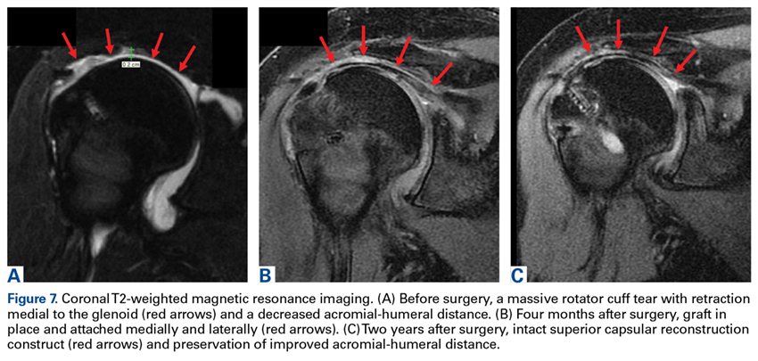
Discussion
Mihata and colleagues10 published 2-year data for their reconstructive procedure with fascia lata autograft. In a modification of their procedure, Dr. Hirahara used dermal allograft to recreate the superior capsule.11 The results of the present 2-year study mirror the clinical outcomes reported by Mihata and colleagues10 and confirm that SCR improves functional outcomes and increases AHD regardless of graft type used.
The outcomes of the SCR patients in our study were significantly better than the outcomes of the historical control patients, who underwent repair of massive RCTs. Although there was no significant difference in the 2 groups’ ASES scores, the control patients had significantly higher postoperative VAS pain scores. We think that, as more patients undergo SCR and the population sample increases, we will see a significant difference in ASES scores as well (our SCR patients already showed a trend toward improved ASES scores).
Compared with RTSA, SCR has fewer risks and fewer complications and does not limit further surgical options.8,9,18 The 9 patients who had surgery with a minimum 2-year follow-up in our study had 4 complications. Six months after surgery, 1 patient fell and tore the infraspinatus and subscapularis muscles. Outcomes continued to improve, and no issues were reported, despite a decrease in AHD, from 8 mm immediately after surgery to 4.6 mm 2 years after surgery.
Two patients were in motor vehicle accidents. In 1 case, the accident occurred about 2 months after surgery. This patient also sustained a possible injury in a fall after receiving general anesthesia for a dental procedure. After having done very well the preceding months, the patient now reported increasing pain and dysfunction. MRI showed loss of glenoid fixation. Improved ASES and VAS pain scores were maintained throughout the follow-up period. AHD was increased at 13 months and mildly decreased at 2 years. Glenoid fixation was obtained with 2 anchors and a double surgeon knot. When possible, however, it is best to add an anchor and double-row fixation, as 3 anchors and a double-row construct are biomechanically stronger.19-24
The other motor vehicle accident occurred about 23 months after surgery. Two months later, a graft rupture was found on US and MRI, but the patient was maintaining full range of motion, AHD, and improved strength. The 1.5-mm graft in this patient was thinner than the 3.5-mm grafts in the rest of the study group. This was the only patient who developed a graft rupture rather than loss of fixation.
If only patients with graft thickness >3.0 mm are included in the data analysis, mean ASES score rises to 89.76, and mean VAS pain score drops to 0. Therefore, we argue against using a graft thinner than 3.5 mm. Our excellent study results indicate that larger grafts are unnecessary. Mihata and colleagues10 used fascia lata grafts of 6 mm to 8 mm. Ultimate load to failure is significantly higher for dermal allograft than for fascia lata graft.25 In SCR, the stronger dermal allograft withstands applied forces and repeated deformations and has excellent clinical outcomes.
Only 1 patient had a failure that required RTSA. VAS pain scores were lower and ASES scores were improved the first year after surgery, but then function deteriorated. The patient said there was no specific precipitating incident. Computed tomography arthrogram, ordered to assess the construct, showed anterior and superior subluxation of the humeral head, even with an intact subscapularis tendon—an indication of underlying instability, which most likely caused the failure. Eighteen months after surgery, the patient was able to undergo RTSA. On further evaluation of this patient’s procedure, it was determined that the graft needed better fixation anteriorly.
Mihata and colleagues10,12,14 indicated that AMC was unnecessary, and our procedure did not require it. However, data in our prospective evaluation began showing improved outcomes with AMC. As dermal allograft is more elastic than fascia lata autograft,25 we concluded that graft tensioning is key to the success of this procedure. Graft tension depends on many factors, including exact measurement of the distances between the anchors to punch holes in the graft, arm position to set the relationship between the anchor distances, and AMC and PMC. We recommend placing the arm in neutral rotation, neutral flexion, and abduction with the patient at rest, based on the size of the patient’s latissimus dorsi. Too much abduction causes overtensioning, and excess rotation or flexion-extension changes the distance between the glenoid and the greater tuberosity asymmetrically, from anterior to posterior. With the arm in neutral position, distances between anchors are accurately measured, and these measurements are used to determine graft size.
Graft tension is also needed to control the amount of elasticity allowed by the graft and thereby maintain stability, as shown by the Poisson ratio, the ratio of transverse contraction to longitudinal extension on a material in the presence of a stretching force. As applied to SCR, it is the ratio of mediolateral elasticity to anteroposterior deformation or constraint. If the graft is appropriately secured in the anteroposterior direction by way of ACM and PMC, elongation in the medial-lateral direction will be limited—reducing the elasticity of the graft, improving overall stability, and ultimately producing better clinical outcomes. This issue was discussed by Burkhart and colleagues26 with respect to the “rotator cable complex,” which now might be best described as the “rotator-capsule cable complex.” In our study, this phenomenon was evident in the finding that patients who had AMC performed did significantly better than patients who did not have AMC performed. The ability of dermal allograft to deform in these dimensions without failure while allowing excellent range of motion makes dermal allograft an exceptional choice for grafting during SCR. Mihata25 also found dermal allograft had a clear advantage in providing better range of motion, whereas fascia lata autograft resulted in a stiffer construct.
Dermal allograft can also incorporate into the body and transform into host tissue. The literature has described musculoskeletal US as an effective diagnostic and interventional tool.27-31 We used it to evaluate graft size, patency, and viability. As can be seen on US, the native rotator cuff does not have any pulsatile vessels and is fed by capillary flow. Dermal allograft has native vasculature built into the tissue. After 4 months to 8 months, presence of pulsatile vessels within the graft at the greater tuberosity indicates clear revascularization and incorporation of the tissue (Figure 6B). Disappearance of pulsatile vessels on US after 1 year indicates transformation to a stabilizing structure analogous to capsule or ligament with capillary flow. US also showed graft hypertrophy after 2 years, supporting a finding of integration and growth.
Conclusion
In the past, patients with irreparable massive RCTs had few good surgical management options, RTSA being the most definitive. SCR is technically challenging and requires use of specific implantation methods but can provide patients with outstanding relief. Our clinical data showed that technically well executed SCR effectively restores the superior restraints in the glenohumeral joint and thereby increases function and decreases pain in patients with irreparable massive RCTs, even after 2 years.
1 Lee BG, Cho NS, Rhee YG. Results of arthroscopic decompression and tuberoplasty for irreparable massive rotator cuff tears. Arthroscopy. 2011;27(10):1341-1350.
2. Liem D, Lengers N, Dedy N, Poetzl W, Steinbeck J, Marquardt B. Arthroscopic debridement of massive irreparable rotator cuff tears. Arthroscopy. 2008;24(7):743-748.
3. Kim SJ, Lee IS, Kim SH, Lee WY, Chun YM. Arthroscopic partial repair of irreparable large to massive rotator cuff tears. Arthroscopy. 2012;28(6):761-768.
4. Wellmann M, Lichtenberg S, da Silva G, Magosch P, Habermeyer P. Results of arthroscopic partial repair of large retracted rotator cuff tears. Arthroscopy. 2013;29(8):1275-1282.
5. Mori D, Funakoshi N, Yamashita F. Arthroscopic surgery of irreparable large or massive rotator cuff tears with low-grade fatty degeneration of the infraspinatus: patch autograft procedure versus partial repair procedure. Arthroscopy. 2013;29(12):1911-1921.
6. Gavriilidis I, Kircher J, Mogasch P, Lichtenberg S, Habermeyer P. Pectoralis major transfer for the treatment of irreparable anterosuperior rotator cuff tears. Int Orthop. 2010;34(5):689-694.
7. Grimberg J, Kany J, Valenti P, Amaravathi R, Ramalingam AT. Arthroscopic-assisted latissimus dorsi tendon transfer for irreparable posterosuperior cuff tears. Arthroscopy. 2015;31(4):599-607.
8. Bedi A, Dines J, Warren RF, Dines DM. Massive tears of the rotator cuff. J Bone Joint Surg Am. 2010;92(9):1894-1908.
9. Ek ET, Neukom L, Catanzaro S, Gerber C. Reverse total shoulder arthroplasty for massive irreparable rotator cuff tears in patients younger than 65 years old: results after five to fifteen years. J Shoulder Elbow Surg. 2013;22(9):1199-1208.
10. Mihata T, Lee TQ, Watanabe C, et al. Clinical results of arthroscopic superior capsule reconstruction for irreparable rotator cuff tears. Arthroscopy. 2013;29(3):459-470.
11. Hirahara AM, Adams CR. Arthroscopic superior capsular reconstruction for treatment of massive irreparable rotator cuff tears. Arthrosc Tech. 2015;4(6):e637-e641.
12. Mihata T, McGarry MH, Kahn T, Goldberg I, Neo M, Lee TQ. Biomechanical role of capsular continuity in superior capsule reconstruction for irreparable tears of the supraspinatus tendon. Am J Sports Med. 2016;44(6):1423-1430.
13. Mihata T, McGarry MH, Ishihara Y, et al. Biomechanical analysis of articular-sided partial-thickness rotator cuff tear and repair. Am J Sports Med. 2015;43(2):439-446.
14. Mihata T, McGarry MH, Pirolo JM, Kinoshita M, Lee TQ. Superior capsule reconstruction to restore superior stability in irreparable rotator cuff tears: a biomechanical cadaveric study. Am J Sports Med. 2012;40(10):2248-2255.
15. Hirahara AM, Andersen WJ. The PASTA bridge: a technique for the arthroscopic repair of PASTA lesions [published online ahead of print September 18, 2017]. Arthrosc Tech. http://dx.doi.org/10.1016/j.eats.2017.06.022.
16. Hamada K, Yamanaka K, Uchiyama Y, Mikasa T, Mikasa M. A radiographic classification of massive rotator cuff tear arthritis. Clin Orthop Relat Res. 2011;469(9):2452-2460.
17. Oh JH, Kim SH, Choi JA, Kim Y, Oh CH. Reliability of the grading system for fatty degeneration of rotator cuff muscles. Clin Orthop Relat Res. 2010;468(6):1558-1564.
18. Boileau P, Sinnerton RJ, Chuinard C, Walch G. Arthroplasty of the shoulder. J Bone Joint Surg Br. 2006;88(5):562-575.
19. Apreleva M, Özbaydar M, Fitzgibbons PG, Warner JJ. Rotator cuff tears: the effect of the reconstruction method on three-dimensional repair site area. Arthroscopy. 2002;18(5):519-526.
20. Baums MH, Spahn G, Steckel H, Fischer A, Schultz W, Klinger HM. Comparative evaluation of the tendon–bone interface contact pressure in different single- versus double-row suture anchor repair techniques. Knee Surg Sports Traumatol Arthrosc. 2009;17(12):1466-1472.
21. Lo IK, Burkhart SS. Double-row arthroscopic rotator cuff repair: re-establishing the footprint of the rotator cuff. Arthroscopy. 2003;19(9):1035-1042.
22. Mazzocca AD, Millett PJ, Guanche CA, Santangelo SA, Arciero RA. Arthroscopic single-row versus double-row suture anchor rotator cuff repair. Am J Sports Med. 2005;33(12):1861-1868.
23. Pauly S, Fiebig D, Kieser B, Albrecht B, Schill A, Scheibel M. Biomechanical comparison of four double-row speed-bridging rotator cuff repair techniques with or without medial or lateral row enhancement. Knee Surg Sports Traumatol Arthrosc. 2011;19(12):2090-2097.
24. Pauly S, Kieser B, Schill A, Gerhardt C, Scheibel M. Biomechanical comparison of 4 double-row suture-bridging rotator cuff repair techniques using different medial-row configurations. Arthroscopy. 2010;26(10):1281-1288.
25. Mihata T. Superior capsule reconstruction using human dermal allograft: a biomechanical cadaveric study. Presentation at: Annual Meeting of the American Academy of Orthopaedic Surgeons; March 1-5, 2016; Orlando, FL.
26. Burkhart SS, Esch JC, Jolson RS. The rotator crescent and rotator cable: an anatomic description of the shoulder’s “suspension bridge.” Arthroscopy. 1993;9(6):611-616.
27. Hirahara AM, Andersen WJ. Ultrasound-guided percutaneous reconstruction of the anterolateral ligament: surgical technique and case report. Am J Orthop. 2016;45(7):418-422, 460.
28. Hirahara AM, Andersen WJ. Ultrasound-guided percutaneous repair of medial patellofemoral ligament: surgical technique and outcomes. Am J Orthop. 2017;46(3):152-157.
29. Hirahara AM, Mackay G, Andersen WJ. Ultrasound-guided InternalBrace of the medial collateral ligament. Arthrosc Tech. Accepted for publication.
30. Hirahara AM, Panero AJ. A guide to ultrasound of the shoulder, part 3: interventional and procedural uses. Am J Orthop. 2016;45(7):440-445.
31. Panero AJ, Hirahara AM. A guide to ultrasound of the shoulder, part 2: the diagnostic evaluation. Am J Orthop. 2016;45(4):233-238.
Take-Home Points
- The SCR is a viable treatment option for massive, irreparable RCTs.
- Arm position and exact measurement between anchors will help ensure proper graft tensioning.
- Anterior and posterior tension and margin convergence are critical to stabilizing the graft.
- Acromial-humeral distance, ASES, and VAS scores are improved and maintained over long-term follow-up.
- The dermal allograft should be 3.0 mm or thicker.
Conventional treatments for irreparable massive rotator cuff tears (RCTs) have ranged from nonoperative care to débridement and biceps tenotomy,1,2 partial cuff repair,3,4 bridging patch grafts,5 tendon transfers,6,7 and reverse total shoulder arthroplasty (RTSA).8,9 Superior capsular reconstruction (SCR), originally described by Mihata and colleagues,10 has been developed as an alternative to these interventions. Dr. Hirahara modified the technique to use dermal allograft instead of fascia lata autograft.10,11
Biomechanical analysis has confirmed the integral role of the superior capsule in shoulder function.10,12-14 In the presence of a massive RCT, the humeral head migrates superiorly, causing significant pain and functional deficits, such as pseudoparalysis. It is theorized that reestablishing this important stabilizer—centering the humeral head in the glenoid and allowing the larger muscles to move the arm about a proper fulcrum—improves function and decreases pain.
Using ultrasonography (US), radiography, magnetic resonance imaging (MRI), clinical outcome scores, and a visual analog scale (VAS) for pain, we prospectively evaluated minimum 2-year clinical outcomes of performing SCR with dermal allograft for irreparable RCTs.
Methods
Except where noted otherwise, all products mentioned in this section were made by Arthrex.
Surgical Technique
The surgical technique used here was described by Hirahara and Adams.11 ArthroFlex dermal allograft was attached to the greater tuberosity and the glenoid, creating a superior restraint that replaced the anatomical superior capsule (Figures 1A, 1B). Some cases included biceps tenotomy, subscapularis repair, or infraspinatus repair.
Medial fixation was obtained with a PASTA (partial articular supraspinatus tendon avulsion) bridge-type construct15 that consisted of two 3.0-mm BioComposite SutureTak anchors (placed medially on the glenoid rim, medial to the labrum) and a 3.5-mm BioComposite Vented SwiveLock. In some cases, a significant amount of tissue was present medially, and the third anchor was not used; instead, a double surgeon knot was used to fixate the double pulley medially.
Posterior margin convergence (PMC) was performed in all cases. Anterior margin convergence (AMC) was performed in only 3 cases.
Clinical Evaluation
All patients who underwent SCR were followed prospectively, and all signed an informed consent form. Between 2014 and the time of this study, 9 patients had surgery with a minimum 2-year follow-up. Before surgery, all patients received a diagnosis of full-thickness RCT with decreased acromial-humeral distance (AHD). One patient had RTSA 18 months after surgery, did not reach the 2-year follow-up, and was excluded from the data analysis. Patients were clinically evaluated on the 100-point American Shoulder and Elbow Surgeons (ASES) shoulder index and on a 10-point VAS for pain—before surgery, monthly for the first 6 months after surgery, then every 6 months until 2 years after surgery, and yearly thereafter. These patients were compared with Dr. Hirahara’s historical control patients, who had undergone repair of massive RCTs. Mean graft size was calculated and reported. Cases were separated and analyzed on the basis of whether AMC was performed. Student t tests were used to determine statistical differences between study patients’ preoperative and postoperative scores, between study and historical control patients, and between patients who had AMC performed and those who did not (P < .05).
Imaging
For all SCR patients, preoperative and postoperative radiographs were obtained in 2 planes: anterior-posterior with arm in neutral rotation, and scapular Y. On anteroposterior radiographs, AHD was measured from the most proximal aspect of the humeral head in a vertical line to the most inferior portion of the acromion (Figures 2A, 2B).
Results
The Table provides an overview of the study results. Eight patients (6 men, 2 women) met the final inclusion criteria for postoperative ASES and VAS data analysis.
AHD was measured on a standard anteroposterior radiograph in neutral rotation. The Hamada grading scale16 was used to classify the massive RCTs before and after surgery. Before surgery, 4 were grade 4A, 1 grade 3, 2 grade 2, and 1 grade 1; immediately after surgery, all were grade 1 (AHD, ≥6 mm). Two years after surgery, 1 patient had an AHD of 4.6 mm after a failure caused by a fall. Mean (SD) preoperative AHD was 4.50 (2.25) mm (range, 1.7-7.9 mm). Radiographs obtained immediately (mean, 1.22 months; range, 1 day-2.73 months) after surgery showed AHD was significantly (P < .0008) increased (mean, 8.48 mm; SD, 1.25 mm; range, 6.0-10.0 mm) (Figure 5).
Mean graft size was 2.9 mm medial × 3.6 mm lateral × 5.4 mm anterior × 5.4 mm posterior. Three patients had AMC performed. There was a significant (P < .05) difference in ASES scores between patients who had AMC performed (93) and those who did not (77).
Ultrasonography
Two weeks to 2 months after surgery, all patients had an intact capsular graft and no pulsatile vessels on US. Between 4 months and 10 months, US showed the construct intact laterally in all cases, a pulsatile vessel in the graft at the tuberosity (evidence of blood flow) in 4 of 5 cases, and a pulsatile vessel hypertrophied in 2 cases (Figures 6A, 6B).
Magnetic Resonance Imaging
Before surgery, 4 patients had Goutallier17 stage 4 rotator cuff muscle degeneration, 2 had stage 3 degeneration, and 2 had stage 2 degeneration. Throughout the follow-up period, US was as effective as MRI in determining graft integrity, graft thickness, and greater tuberosity fixation. Therefore, the SCRs were assessed primarily with US. MRI was ordered only if a failure was suspected or if the patient had some form of trauma. A total of 7 MRIs were ordered for 5 of the 8 patients in the study. The graft was intact in 4 of the 5 (Figures 7A-7C) and ruptured in the fifth.
Discussion
Mihata and colleagues10 published 2-year data for their reconstructive procedure with fascia lata autograft. In a modification of their procedure, Dr. Hirahara used dermal allograft to recreate the superior capsule.11 The results of the present 2-year study mirror the clinical outcomes reported by Mihata and colleagues10 and confirm that SCR improves functional outcomes and increases AHD regardless of graft type used.
The outcomes of the SCR patients in our study were significantly better than the outcomes of the historical control patients, who underwent repair of massive RCTs. Although there was no significant difference in the 2 groups’ ASES scores, the control patients had significantly higher postoperative VAS pain scores. We think that, as more patients undergo SCR and the population sample increases, we will see a significant difference in ASES scores as well (our SCR patients already showed a trend toward improved ASES scores).
Compared with RTSA, SCR has fewer risks and fewer complications and does not limit further surgical options.8,9,18 The 9 patients who had surgery with a minimum 2-year follow-up in our study had 4 complications. Six months after surgery, 1 patient fell and tore the infraspinatus and subscapularis muscles. Outcomes continued to improve, and no issues were reported, despite a decrease in AHD, from 8 mm immediately after surgery to 4.6 mm 2 years after surgery.
Two patients were in motor vehicle accidents. In 1 case, the accident occurred about 2 months after surgery. This patient also sustained a possible injury in a fall after receiving general anesthesia for a dental procedure. After having done very well the preceding months, the patient now reported increasing pain and dysfunction. MRI showed loss of glenoid fixation. Improved ASES and VAS pain scores were maintained throughout the follow-up period. AHD was increased at 13 months and mildly decreased at 2 years. Glenoid fixation was obtained with 2 anchors and a double surgeon knot. When possible, however, it is best to add an anchor and double-row fixation, as 3 anchors and a double-row construct are biomechanically stronger.19-24
The other motor vehicle accident occurred about 23 months after surgery. Two months later, a graft rupture was found on US and MRI, but the patient was maintaining full range of motion, AHD, and improved strength. The 1.5-mm graft in this patient was thinner than the 3.5-mm grafts in the rest of the study group. This was the only patient who developed a graft rupture rather than loss of fixation.
If only patients with graft thickness >3.0 mm are included in the data analysis, mean ASES score rises to 89.76, and mean VAS pain score drops to 0. Therefore, we argue against using a graft thinner than 3.5 mm. Our excellent study results indicate that larger grafts are unnecessary. Mihata and colleagues10 used fascia lata grafts of 6 mm to 8 mm. Ultimate load to failure is significantly higher for dermal allograft than for fascia lata graft.25 In SCR, the stronger dermal allograft withstands applied forces and repeated deformations and has excellent clinical outcomes.
Only 1 patient had a failure that required RTSA. VAS pain scores were lower and ASES scores were improved the first year after surgery, but then function deteriorated. The patient said there was no specific precipitating incident. Computed tomography arthrogram, ordered to assess the construct, showed anterior and superior subluxation of the humeral head, even with an intact subscapularis tendon—an indication of underlying instability, which most likely caused the failure. Eighteen months after surgery, the patient was able to undergo RTSA. On further evaluation of this patient’s procedure, it was determined that the graft needed better fixation anteriorly.
Mihata and colleagues10,12,14 indicated that AMC was unnecessary, and our procedure did not require it. However, data in our prospective evaluation began showing improved outcomes with AMC. As dermal allograft is more elastic than fascia lata autograft,25 we concluded that graft tensioning is key to the success of this procedure. Graft tension depends on many factors, including exact measurement of the distances between the anchors to punch holes in the graft, arm position to set the relationship between the anchor distances, and AMC and PMC. We recommend placing the arm in neutral rotation, neutral flexion, and abduction with the patient at rest, based on the size of the patient’s latissimus dorsi. Too much abduction causes overtensioning, and excess rotation or flexion-extension changes the distance between the glenoid and the greater tuberosity asymmetrically, from anterior to posterior. With the arm in neutral position, distances between anchors are accurately measured, and these measurements are used to determine graft size.
Graft tension is also needed to control the amount of elasticity allowed by the graft and thereby maintain stability, as shown by the Poisson ratio, the ratio of transverse contraction to longitudinal extension on a material in the presence of a stretching force. As applied to SCR, it is the ratio of mediolateral elasticity to anteroposterior deformation or constraint. If the graft is appropriately secured in the anteroposterior direction by way of ACM and PMC, elongation in the medial-lateral direction will be limited—reducing the elasticity of the graft, improving overall stability, and ultimately producing better clinical outcomes. This issue was discussed by Burkhart and colleagues26 with respect to the “rotator cable complex,” which now might be best described as the “rotator-capsule cable complex.” In our study, this phenomenon was evident in the finding that patients who had AMC performed did significantly better than patients who did not have AMC performed. The ability of dermal allograft to deform in these dimensions without failure while allowing excellent range of motion makes dermal allograft an exceptional choice for grafting during SCR. Mihata25 also found dermal allograft had a clear advantage in providing better range of motion, whereas fascia lata autograft resulted in a stiffer construct.
Dermal allograft can also incorporate into the body and transform into host tissue. The literature has described musculoskeletal US as an effective diagnostic and interventional tool.27-31 We used it to evaluate graft size, patency, and viability. As can be seen on US, the native rotator cuff does not have any pulsatile vessels and is fed by capillary flow. Dermal allograft has native vasculature built into the tissue. After 4 months to 8 months, presence of pulsatile vessels within the graft at the greater tuberosity indicates clear revascularization and incorporation of the tissue (Figure 6B). Disappearance of pulsatile vessels on US after 1 year indicates transformation to a stabilizing structure analogous to capsule or ligament with capillary flow. US also showed graft hypertrophy after 2 years, supporting a finding of integration and growth.
Conclusion
In the past, patients with irreparable massive RCTs had few good surgical management options, RTSA being the most definitive. SCR is technically challenging and requires use of specific implantation methods but can provide patients with outstanding relief. Our clinical data showed that technically well executed SCR effectively restores the superior restraints in the glenohumeral joint and thereby increases function and decreases pain in patients with irreparable massive RCTs, even after 2 years.
1 Lee BG, Cho NS, Rhee YG. Results of arthroscopic decompression and tuberoplasty for irreparable massive rotator cuff tears. Arthroscopy. 2011;27(10):1341-1350.
2. Liem D, Lengers N, Dedy N, Poetzl W, Steinbeck J, Marquardt B. Arthroscopic debridement of massive irreparable rotator cuff tears. Arthroscopy. 2008;24(7):743-748.
3. Kim SJ, Lee IS, Kim SH, Lee WY, Chun YM. Arthroscopic partial repair of irreparable large to massive rotator cuff tears. Arthroscopy. 2012;28(6):761-768.
4. Wellmann M, Lichtenberg S, da Silva G, Magosch P, Habermeyer P. Results of arthroscopic partial repair of large retracted rotator cuff tears. Arthroscopy. 2013;29(8):1275-1282.
5. Mori D, Funakoshi N, Yamashita F. Arthroscopic surgery of irreparable large or massive rotator cuff tears with low-grade fatty degeneration of the infraspinatus: patch autograft procedure versus partial repair procedure. Arthroscopy. 2013;29(12):1911-1921.
6. Gavriilidis I, Kircher J, Mogasch P, Lichtenberg S, Habermeyer P. Pectoralis major transfer for the treatment of irreparable anterosuperior rotator cuff tears. Int Orthop. 2010;34(5):689-694.
7. Grimberg J, Kany J, Valenti P, Amaravathi R, Ramalingam AT. Arthroscopic-assisted latissimus dorsi tendon transfer for irreparable posterosuperior cuff tears. Arthroscopy. 2015;31(4):599-607.
8. Bedi A, Dines J, Warren RF, Dines DM. Massive tears of the rotator cuff. J Bone Joint Surg Am. 2010;92(9):1894-1908.
9. Ek ET, Neukom L, Catanzaro S, Gerber C. Reverse total shoulder arthroplasty for massive irreparable rotator cuff tears in patients younger than 65 years old: results after five to fifteen years. J Shoulder Elbow Surg. 2013;22(9):1199-1208.
10. Mihata T, Lee TQ, Watanabe C, et al. Clinical results of arthroscopic superior capsule reconstruction for irreparable rotator cuff tears. Arthroscopy. 2013;29(3):459-470.
11. Hirahara AM, Adams CR. Arthroscopic superior capsular reconstruction for treatment of massive irreparable rotator cuff tears. Arthrosc Tech. 2015;4(6):e637-e641.
12. Mihata T, McGarry MH, Kahn T, Goldberg I, Neo M, Lee TQ. Biomechanical role of capsular continuity in superior capsule reconstruction for irreparable tears of the supraspinatus tendon. Am J Sports Med. 2016;44(6):1423-1430.
13. Mihata T, McGarry MH, Ishihara Y, et al. Biomechanical analysis of articular-sided partial-thickness rotator cuff tear and repair. Am J Sports Med. 2015;43(2):439-446.
14. Mihata T, McGarry MH, Pirolo JM, Kinoshita M, Lee TQ. Superior capsule reconstruction to restore superior stability in irreparable rotator cuff tears: a biomechanical cadaveric study. Am J Sports Med. 2012;40(10):2248-2255.
15. Hirahara AM, Andersen WJ. The PASTA bridge: a technique for the arthroscopic repair of PASTA lesions [published online ahead of print September 18, 2017]. Arthrosc Tech. http://dx.doi.org/10.1016/j.eats.2017.06.022.
16. Hamada K, Yamanaka K, Uchiyama Y, Mikasa T, Mikasa M. A radiographic classification of massive rotator cuff tear arthritis. Clin Orthop Relat Res. 2011;469(9):2452-2460.
17. Oh JH, Kim SH, Choi JA, Kim Y, Oh CH. Reliability of the grading system for fatty degeneration of rotator cuff muscles. Clin Orthop Relat Res. 2010;468(6):1558-1564.
18. Boileau P, Sinnerton RJ, Chuinard C, Walch G. Arthroplasty of the shoulder. J Bone Joint Surg Br. 2006;88(5):562-575.
19. Apreleva M, Özbaydar M, Fitzgibbons PG, Warner JJ. Rotator cuff tears: the effect of the reconstruction method on three-dimensional repair site area. Arthroscopy. 2002;18(5):519-526.
20. Baums MH, Spahn G, Steckel H, Fischer A, Schultz W, Klinger HM. Comparative evaluation of the tendon–bone interface contact pressure in different single- versus double-row suture anchor repair techniques. Knee Surg Sports Traumatol Arthrosc. 2009;17(12):1466-1472.
21. Lo IK, Burkhart SS. Double-row arthroscopic rotator cuff repair: re-establishing the footprint of the rotator cuff. Arthroscopy. 2003;19(9):1035-1042.
22. Mazzocca AD, Millett PJ, Guanche CA, Santangelo SA, Arciero RA. Arthroscopic single-row versus double-row suture anchor rotator cuff repair. Am J Sports Med. 2005;33(12):1861-1868.
23. Pauly S, Fiebig D, Kieser B, Albrecht B, Schill A, Scheibel M. Biomechanical comparison of four double-row speed-bridging rotator cuff repair techniques with or without medial or lateral row enhancement. Knee Surg Sports Traumatol Arthrosc. 2011;19(12):2090-2097.
24. Pauly S, Kieser B, Schill A, Gerhardt C, Scheibel M. Biomechanical comparison of 4 double-row suture-bridging rotator cuff repair techniques using different medial-row configurations. Arthroscopy. 2010;26(10):1281-1288.
25. Mihata T. Superior capsule reconstruction using human dermal allograft: a biomechanical cadaveric study. Presentation at: Annual Meeting of the American Academy of Orthopaedic Surgeons; March 1-5, 2016; Orlando, FL.
26. Burkhart SS, Esch JC, Jolson RS. The rotator crescent and rotator cable: an anatomic description of the shoulder’s “suspension bridge.” Arthroscopy. 1993;9(6):611-616.
27. Hirahara AM, Andersen WJ. Ultrasound-guided percutaneous reconstruction of the anterolateral ligament: surgical technique and case report. Am J Orthop. 2016;45(7):418-422, 460.
28. Hirahara AM, Andersen WJ. Ultrasound-guided percutaneous repair of medial patellofemoral ligament: surgical technique and outcomes. Am J Orthop. 2017;46(3):152-157.
29. Hirahara AM, Mackay G, Andersen WJ. Ultrasound-guided InternalBrace of the medial collateral ligament. Arthrosc Tech. Accepted for publication.
30. Hirahara AM, Panero AJ. A guide to ultrasound of the shoulder, part 3: interventional and procedural uses. Am J Orthop. 2016;45(7):440-445.
31. Panero AJ, Hirahara AM. A guide to ultrasound of the shoulder, part 2: the diagnostic evaluation. Am J Orthop. 2016;45(4):233-238.
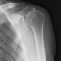
Ultrasound-Guided Percutaneous Repair of Medial Patellofemoral Ligament: Surgical Technique and Outcomes
Take-Home Points
- Use ultrasound to identify integrity and location of MPFL tear.
- Anatomic repair allows native tissue to reintegrate into bone.
- Repairs done early can prevent complications of recurrent instability.
- Repair maintains biological and proprioceptive qualities of tissue.
- 10Ultrasound-guided percutaneous repair is quick and effective.
The medial patellofemoral ligament (MPFL) is the primary passive restraint to lateral patellar excursion1-5 and helps control patellar tilt and rotation.6,7 More than 90% of lateral patellar dislocations cause the MPFL to rupture, and roughly 90% of these detachments involve the femoral insertion.4 Ensuing patellar instability often results from MPFL insufficiency. It has been suggested that re-creating the anatomy and functionality of this ligament is of utmost importance in restoring normal patellar biomechanics.1-5,7,8
Anatomical risk factors for recurrent patellar instability include patella alta, increased tibial tuberosity-trochlear groove (TT-TG) distance, trochlear dysplasia, and torsional abnormalities.1-4,6 A medial reefing technique with a lateral tissue release traditionally was used to restore proper kinematics, but was shown to have associated postoperative issues.9


Methods
Patient Demographics
Dr. Hirahara developed this technique in 2013 and performed it 11 times between 2013 and 2016. Of the 11 patients, 1 was excluded from our retrospective analysis because of trochlear dysplasia, now considered a relative contraindication. Of the remaining 10 patients, 5 (50%) had the repair performed on the right knee. Eight patients (80%) were female. Mean (SD) age was 17.21 (3.53) years. One patient had concurrent femur- and patella-side detachments; otherwise, 6 (60%) of 10 repairs were performed exclusively at the patella. We grade patellar instability according to amount of glide based on patellar width and quadrants. Normal lateral displacement was usually 1 to 2 quadrants of lateral glide relative to the contralateral side. Before surgery, 6 (60%) of the 10 patients presented with lateral glide of 3 quadrants, and 3 (30%) presented with lateral glide of 4 quadrants. All had patellar instability apprehension on physical examination.
Surgical Indications
Before surgery, MPFL integrity is determined by ultrasound evaluation. Repair is considered if the MPFL has a femur- or patella-side tear and is of adequate quantity and quality, and if there are minimal or no arthritic changes (Table 2). 
Surgical Technique
The patient is brought to the operating room and placed supine. Patellar stability of the affected knee is assessed and compared with that of the contralateral side with patellar glide. The knee is prepared and draped in usual sterile fashion. With the knee flexed at 90º, a tourniquet is inflated. Diagnostic arthroscopy is performed with standard anteromedial and anterolateral portals, and, if necessary, arthroscopic procedures are performed.
Femoral Attachment Repair
With the leg in extension, ultrasound is used to identify the tear at the femoral attachment (watch part 1 of the video). A spinal needle is placed at the femoral insertion, typically just anterior and distal to the adductor tubercle (Figure 4).10 
Patellar Attachment Repair
With the leg in extension, ultrasound is used to identify where the MPFL is detached from the patella (watch part 2 of the video). A spinal needle is placed at the detachment site (Figure 5). A scalpel is used to make a 1-cm incision down to the patella. 
In this description, we showcase knotless and knotted techniques for each repair site. Either method is appropriate for the 2 repair sites. Owing to the superficial nature of the attachment sites—they may have very little fat, particularly at the patella—knot stacks are more prominent, can be felt after surgery, and have the potential to irritate surrounding tissues. Therefore, we prefer knotless fixation for both sites.
Rehabilitation
Rehabilitation after MPFL repair is much like rehabilitation after quadriceps tendon repair. The patient is locked in a brace in full extension when up and moving. Early weight-bearing and minimal use of assistive devices (crutches) are allowed because, when the leg is in full extension, there is no tension at the repair sites. Rehabilitation begins within 1 week, and normal daily function is quickly attained. The protocol emphasizes pain-free motion and suitable patellar mobility, and allows the immobilizing brace to be unlocked for exercise and sitting. During the first 4 weeks, quadriceps activation is limited; progression to full ROM occurs by 4 to 6 weeks. During the strengthening phase, loading the knee in early flexion should be avoided. Return to heavy lifting, physical activity, and sports is delayed until after 6 months in order to allow the construct to mature and integrate. Once the patient has satisfied all the strength, ROM, and functional outcome measurements, a brace is no longer required during sports and normal activity.
Results
Mean tourniquet time for each procedure, which includes diagnostic arthroscopy and ultrasound-guided percutaneous repair, was 26.9 minutes. 
Discussion
Conservative management typically is recommended for acute patellar dislocations. In the event of failed conservative management or chronic patellar instability, surgical intervention is indicated. Studies have found that conservative management has recurrent-dislocation rates of 35% at 3-year follow-up and 73% at 6-year follow-up, and recurrent dislocations significantly increase patients’ risk of developing chondral and bony damage.13 MPFL repair is designed to restore proper patellar tracking and kinematics while maintaining the anatomical tissue. Lateral patellar dislocations often cause the MPFL to rupture; tears are reported in more than 90% of incidents.4 The significant rate indicates that, even after a single patellar dislocation, the MPFL should be evaluated. The MPFL contributes 50% to 60% of the medial stabilizing force during patellar tracking1,7,14 and is the primary restraint to lateral patellar excursion and excessive patellar tilt and rotation.1-5 Its absence plays a key role in recurrent lateral patellar instability. With this structure being so important, proper identification and intervention are vital. Studies have established that redislocation rates are significantly higher for nonoperatively (vs operatively) treated primary patellar dislocations.13 Simple and accurate percutaneous repair of the MPFL should be performed early to avoid the long-term complications of recurrent instability that could damage the cartilage and bone of the patella and trochlea.
The primary advantage of this technique is its novel use of musculoskeletal ultrasound to accurately identify anatomy and pathology and the placement of anatomical repairs. Accurate preoperative and intraoperative assessment of MPFL anatomy is vital to the success of a procedure. Descriptions of MPFL anatomy suggest discrepancies in the exact locations of the femoral and patellar attachments.2,5,7,10,12,15,16 Tanaka5 noted that, even within paired knees, there was “marked variability” in the MPFL insertions. McCarthy and colleagues10 contended the femoral attachment of the MPFL is just anterior and distal to the adductor tubercle, the landmark addressed in this technique. Steensen and colleagues16 described this attachment site as being statistically the “single most important point affecting isometry” of the MPFL. Sallay and colleagues4 asserted that an overwhelming majority of MPFL tears (87%) occur at the adductor tubercle. The variable distribution of tear locations and the importance of re-creating patient anatomy further highlight the need for individualized treatment, which is afforded by ultrasound. Fluoroscopy has been inadequate in identifying MPFL anatomy; this modality is difficult, cumbersome, inaccurate, and inconsistent.11,12 Conversely, ultrasound provides real-time visualization of anatomy and allows for precise identification of MPFL attachments and accurate placement of suture anchors for repair during surgery (Figures 3, 4).
For femur-side and patella-side tears, repairs can and should be performed. For midsubstance tears, however, repair is not feasible, and reconstruction is appropriate. MPFL repair is superior to reconstruction in several ways. Repair is a simple percutaneous procedure that had a mean tourniquet time of 26.9 minutes in this study. For tissue that is quantitatively and qualitatively adequate, repair allows the structure to reintegrate into bone without total reconstruction. In the event of multiple tears, the percutaneous procedure allows for repair of each attachment. As the MPFL sits between the second and third tissue layers of the medial knee, reconstruction can be difficult and invasive and require establishment of a between-layers plane, which can disrupt adjacent tissue.4,7,17 Repair also maintains native tissue and its neurovascular and proprioceptive properties.
Reconstruction of the MPFL has become the gold-standard treatment for recurrent lateral patellar instability but has limitations and complications.3,7,12,17 Reconstruction techniques use either surface anatomy palpation (requiring large incisions) or fluoroscopy to identify tunnel placement locations, and accurate placement has often been difficult and inconsistent. Our repair technique has several advantages over reconstruction. It does not burn any bridges; it allows for subsequent reconstruction. It does not require a graft and, using small suture anchors instead of large sockets and anchors, involves less bone loss. It also allows for early repair of tears—patients can return to activities, sports, and work quicker—and avoids the risk of chondral and bony damage with recurrent dislocations. According to our review of the MPFL repairs performed by Dr. Hirahara starting in 2013, the procedure is quick and successful and has outstanding outcomes.
Another treatment option for recurrent lateral patellar instability combines reefing of the medial patellofemoral tissues with a lateral release. This combination has had several postoperative complications and is no longer indicated.9 TT transfer and trochleoplasty procedures have been developed to address different aspects of patellar instability, increased TT-TG distance, and dysplastic trochlea (Table 2). Both types of procedures are highly invasive and difficult to perform, requiring technical expertise. They are best used when warranted by the anatomy, but this is uncommon. The technique we have presented allows for easy and reliable repair of dislocations in the absence of associated pathology that would require larger, more complex surgery. The ease of use and accuracy of musculoskeletal ultrasound make this technique superior to others.
Conclusion
The MPFL is a vital static stabilizer of the patella and as such should be evaluated in the setting of patellar injury. The novel preoperative and intraoperative use of musculoskeletal ultrasound described in this article allows for easy real-time identification of the MPFL and simple and accurate percutaneous repair of torn structures. Nonoperative treatments of acute patellar dislocations have higher rates of recurrent dislocations, which put patella and trochlea at risk for bony and chondral damage. Given appropriate tear location and tissue quality, repairs should be considered early and before reconstruction. To our knowledge, a reliable, easily reproducible MPFL repair was not described until now. We have reported on use of such a technique and on its promising patient outcomes, which should be considered when addressing MPFL injuries.
Am J Orthop. 2017;46(3):152-157. Copyright Frontline Medical Communications Inc. 2017. All rights reserved.
1. Desio SM, Burks RT, Bachus KN. Soft tissue restraints to lateral patellar translation in the human knee. Am J Sports Med. 1998;26(1):59-65.
2. Nomura E, Inoue M, Osada N. Anatomical analysis of the medial patellofemoral ligament of the knee, especially the femoral attachment. Knee Surg Sports Traumatol Arthrosc. 2005;13(7):510-515.
3. Petri M, Ettinger M, Stuebig T, et al. Current concepts for patellar dislocation. Arch Trauma Res. 2015;4(3):e29301.
4. Sallay PI, Poggi J, Speer KP, Garrett WE. Acute dislocation of the patella. A correlative pathoanatomic study. Am J Sports Med. 1996;24(1):52-60.
5. Tanaka MJ. Variability in the patellar attachment of the medial patellofemoral ligament. Arthroscopy. 2016;32(8):1667-1670.
6. Philippot R, Boyer B, Testa R, Farizon F, Moyen B. The role of the medial ligamentous structures on patellar tracking during knee flexion. Knee Surg Sports Traumatol Arthrosc. 2012;20(2):331-336.
7. Philippot R, Chouteau J, Wegrzyn J, Testa R, Fessy MH, Moyen B. Medial patellofemoral ligament anatomy: implications for its surgical reconstruction. Knee Surg Sports Traumatol Arthrosc. 2009;17(5):475-479.
8. Ahmad CS, Stein BE, Matuz D, Henry JH. Immediate surgical repair of the medial patellar stabilizers for acute patellar dislocation. A review of eight cases. Am J Sports Med. 2000;28(6):804-810.
9. Song GY, Hong L, Zhang H, Zhang J, Li Y, Feng H. Iatrogenic medial patellar instability following lateral retinacular release of the knee joint. Knee Surg Sports Traumatol Arthrosc. 2016;24(9):2825-2830.
10. McCarthy M, Ridley TJ, Bollier M, Wolf B, Albright J, Amendola A. Femoral tunnel placement in medial patellofemoral ligament reconstruction. Iowa Orthop J. 2013;33:58-63.
11. Redfern J, Kamath G, Burks R. Anatomical confirmation of the use of radiographic landmarks in medial patellofemoral ligament reconstruction. Am J Sports Med. 2010;38(2):293-297.
12. Barnett AJ, Howells NR, Burston BJ, Ansari A, Clark D, Eldridge JD. Radiographic landmarks for tunnel placement in reconstruction of the medial patellofemoral ligament. Knee Surg Sports Traumatol Arthrosc. 2012;20(12):2380-2384.
13. Regalado G, Lintula H, Kokki H, Kröger H, Väätäinen U, Eskelinen M. Six-year outcome after non-surgical versus surgical treatment of acute primary patellar dislocation in adolescents: a prospective randomized trial. Knee Surg Sports Traumatol Arthrosc. 2016;24(1):6-11.
14. Sandmeier RH, Burks RT, Bachus KN, Billings A. The effect of reconstruction of the medial patellofemoral ligament on patellar tracking. Am J Sports Med. 2000;28(3):345-349.
15. Baldwin JL. The anatomy of the medial patellofemoral ligament. Am J Sports Med. 2009;37(12):2355-2361.
16. Steensen RN, Dopirak RM, McDonald WG 3rd. The anatomy and isometry of the medial patellofemoral ligament: implications for reconstruction. Am J Sports Med. 2004;32(6):1509-1513.
17. Godin JA, Karas V, Visgauss JD, Garrett WE. Medial patellofemoral ligament reconstruction using a femoral loop button fixation technique. Arthrosc Tech. 2015;4(5):e601-e607.
Take-Home Points
- Use ultrasound to identify integrity and location of MPFL tear.
- Anatomic repair allows native tissue to reintegrate into bone.
- Repairs done early can prevent complications of recurrent instability.
- Repair maintains biological and proprioceptive qualities of tissue.
- 10Ultrasound-guided percutaneous repair is quick and effective.
The medial patellofemoral ligament (MPFL) is the primary passive restraint to lateral patellar excursion1-5 and helps control patellar tilt and rotation.6,7 More than 90% of lateral patellar dislocations cause the MPFL to rupture, and roughly 90% of these detachments involve the femoral insertion.4 Ensuing patellar instability often results from MPFL insufficiency. It has been suggested that re-creating the anatomy and functionality of this ligament is of utmost importance in restoring normal patellar biomechanics.1-5,7,8
Anatomical risk factors for recurrent patellar instability include patella alta, increased tibial tuberosity-trochlear groove (TT-TG) distance, trochlear dysplasia, and torsional abnormalities.1-4,6 A medial reefing technique with a lateral tissue release traditionally was used to restore proper kinematics, but was shown to have associated postoperative issues.9
Methods
Patient Demographics
Dr. Hirahara developed this technique in 2013 and performed it 11 times between 2013 and 2016. Of the 11 patients, 1 was excluded from our retrospective analysis because of trochlear dysplasia, now considered a relative contraindication. Of the remaining 10 patients, 5 (50%) had the repair performed on the right knee. Eight patients (80%) were female. Mean (SD) age was 17.21 (3.53) years. One patient had concurrent femur- and patella-side detachments; otherwise, 6 (60%) of 10 repairs were performed exclusively at the patella. We grade patellar instability according to amount of glide based on patellar width and quadrants. Normal lateral displacement was usually 1 to 2 quadrants of lateral glide relative to the contralateral side. Before surgery, 6 (60%) of the 10 patients presented with lateral glide of 3 quadrants, and 3 (30%) presented with lateral glide of 4 quadrants. All had patellar instability apprehension on physical examination.
Surgical Indications
Before surgery, MPFL integrity is determined by ultrasound evaluation. Repair is considered if the MPFL has a femur- or patella-side tear and is of adequate quantity and quality, and if there are minimal or no arthritic changes (Table 2).
Surgical Technique
The patient is brought to the operating room and placed supine. Patellar stability of the affected knee is assessed and compared with that of the contralateral side with patellar glide. The knee is prepared and draped in usual sterile fashion. With the knee flexed at 90º, a tourniquet is inflated. Diagnostic arthroscopy is performed with standard anteromedial and anterolateral portals, and, if necessary, arthroscopic procedures are performed.
Femoral Attachment Repair
With the leg in extension, ultrasound is used to identify the tear at the femoral attachment (watch part 1 of the video). A spinal needle is placed at the femoral insertion, typically just anterior and distal to the adductor tubercle (Figure 4).10
Patellar Attachment Repair
With the leg in extension, ultrasound is used to identify where the MPFL is detached from the patella (watch part 2 of the video). A spinal needle is placed at the detachment site (Figure 5). A scalpel is used to make a 1-cm incision down to the patella.
In this description, we showcase knotless and knotted techniques for each repair site. Either method is appropriate for the 2 repair sites. Owing to the superficial nature of the attachment sites—they may have very little fat, particularly at the patella—knot stacks are more prominent, can be felt after surgery, and have the potential to irritate surrounding tissues. Therefore, we prefer knotless fixation for both sites.
Rehabilitation
Rehabilitation after MPFL repair is much like rehabilitation after quadriceps tendon repair. The patient is locked in a brace in full extension when up and moving. Early weight-bearing and minimal use of assistive devices (crutches) are allowed because, when the leg is in full extension, there is no tension at the repair sites. Rehabilitation begins within 1 week, and normal daily function is quickly attained. The protocol emphasizes pain-free motion and suitable patellar mobility, and allows the immobilizing brace to be unlocked for exercise and sitting. During the first 4 weeks, quadriceps activation is limited; progression to full ROM occurs by 4 to 6 weeks. During the strengthening phase, loading the knee in early flexion should be avoided. Return to heavy lifting, physical activity, and sports is delayed until after 6 months in order to allow the construct to mature and integrate. Once the patient has satisfied all the strength, ROM, and functional outcome measurements, a brace is no longer required during sports and normal activity.
Results
Mean tourniquet time for each procedure, which includes diagnostic arthroscopy and ultrasound-guided percutaneous repair, was 26.9 minutes.
Discussion
Conservative management typically is recommended for acute patellar dislocations. In the event of failed conservative management or chronic patellar instability, surgical intervention is indicated. Studies have found that conservative management has recurrent-dislocation rates of 35% at 3-year follow-up and 73% at 6-year follow-up, and recurrent dislocations significantly increase patients’ risk of developing chondral and bony damage.13 MPFL repair is designed to restore proper patellar tracking and kinematics while maintaining the anatomical tissue. Lateral patellar dislocations often cause the MPFL to rupture; tears are reported in more than 90% of incidents.4 The significant rate indicates that, even after a single patellar dislocation, the MPFL should be evaluated. The MPFL contributes 50% to 60% of the medial stabilizing force during patellar tracking1,7,14 and is the primary restraint to lateral patellar excursion and excessive patellar tilt and rotation.1-5 Its absence plays a key role in recurrent lateral patellar instability. With this structure being so important, proper identification and intervention are vital. Studies have established that redislocation rates are significantly higher for nonoperatively (vs operatively) treated primary patellar dislocations.13 Simple and accurate percutaneous repair of the MPFL should be performed early to avoid the long-term complications of recurrent instability that could damage the cartilage and bone of the patella and trochlea.
The primary advantage of this technique is its novel use of musculoskeletal ultrasound to accurately identify anatomy and pathology and the placement of anatomical repairs. Accurate preoperative and intraoperative assessment of MPFL anatomy is vital to the success of a procedure. Descriptions of MPFL anatomy suggest discrepancies in the exact locations of the femoral and patellar attachments.2,5,7,10,12,15,16 Tanaka5 noted that, even within paired knees, there was “marked variability” in the MPFL insertions. McCarthy and colleagues10 contended the femoral attachment of the MPFL is just anterior and distal to the adductor tubercle, the landmark addressed in this technique. Steensen and colleagues16 described this attachment site as being statistically the “single most important point affecting isometry” of the MPFL. Sallay and colleagues4 asserted that an overwhelming majority of MPFL tears (87%) occur at the adductor tubercle. The variable distribution of tear locations and the importance of re-creating patient anatomy further highlight the need for individualized treatment, which is afforded by ultrasound. Fluoroscopy has been inadequate in identifying MPFL anatomy; this modality is difficult, cumbersome, inaccurate, and inconsistent.11,12 Conversely, ultrasound provides real-time visualization of anatomy and allows for precise identification of MPFL attachments and accurate placement of suture anchors for repair during surgery (Figures 3, 4).
For femur-side and patella-side tears, repairs can and should be performed. For midsubstance tears, however, repair is not feasible, and reconstruction is appropriate. MPFL repair is superior to reconstruction in several ways. Repair is a simple percutaneous procedure that had a mean tourniquet time of 26.9 minutes in this study. For tissue that is quantitatively and qualitatively adequate, repair allows the structure to reintegrate into bone without total reconstruction. In the event of multiple tears, the percutaneous procedure allows for repair of each attachment. As the MPFL sits between the second and third tissue layers of the medial knee, reconstruction can be difficult and invasive and require establishment of a between-layers plane, which can disrupt adjacent tissue.4,7,17 Repair also maintains native tissue and its neurovascular and proprioceptive properties.
Reconstruction of the MPFL has become the gold-standard treatment for recurrent lateral patellar instability but has limitations and complications.3,7,12,17 Reconstruction techniques use either surface anatomy palpation (requiring large incisions) or fluoroscopy to identify tunnel placement locations, and accurate placement has often been difficult and inconsistent. Our repair technique has several advantages over reconstruction. It does not burn any bridges; it allows for subsequent reconstruction. It does not require a graft and, using small suture anchors instead of large sockets and anchors, involves less bone loss. It also allows for early repair of tears—patients can return to activities, sports, and work quicker—and avoids the risk of chondral and bony damage with recurrent dislocations. According to our review of the MPFL repairs performed by Dr. Hirahara starting in 2013, the procedure is quick and successful and has outstanding outcomes.
Another treatment option for recurrent lateral patellar instability combines reefing of the medial patellofemoral tissues with a lateral release. This combination has had several postoperative complications and is no longer indicated.9 TT transfer and trochleoplasty procedures have been developed to address different aspects of patellar instability, increased TT-TG distance, and dysplastic trochlea (Table 2). Both types of procedures are highly invasive and difficult to perform, requiring technical expertise. They are best used when warranted by the anatomy, but this is uncommon. The technique we have presented allows for easy and reliable repair of dislocations in the absence of associated pathology that would require larger, more complex surgery. The ease of use and accuracy of musculoskeletal ultrasound make this technique superior to others.
Conclusion
The MPFL is a vital static stabilizer of the patella and as such should be evaluated in the setting of patellar injury. The novel preoperative and intraoperative use of musculoskeletal ultrasound described in this article allows for easy real-time identification of the MPFL and simple and accurate percutaneous repair of torn structures. Nonoperative treatments of acute patellar dislocations have higher rates of recurrent dislocations, which put patella and trochlea at risk for bony and chondral damage. Given appropriate tear location and tissue quality, repairs should be considered early and before reconstruction. To our knowledge, a reliable, easily reproducible MPFL repair was not described until now. We have reported on use of such a technique and on its promising patient outcomes, which should be considered when addressing MPFL injuries.
Am J Orthop. 2017;46(3):152-157. Copyright Frontline Medical Communications Inc. 2017. All rights reserved.
1. Desio SM, Burks RT, Bachus KN. Soft tissue restraints to lateral patellar translation in the human knee. Am J Sports Med. 1998;26(1):59-65.
2. Nomura E, Inoue M, Osada N. Anatomical analysis of the medial patellofemoral ligament of the knee, especially the femoral attachment. Knee Surg Sports Traumatol Arthrosc. 2005;13(7):510-515.
3. Petri M, Ettinger M, Stuebig T, et al. Current concepts for patellar dislocation. Arch Trauma Res. 2015;4(3):e29301.
4. Sallay PI, Poggi J, Speer KP, Garrett WE. Acute dislocation of the patella. A correlative pathoanatomic study. Am J Sports Med. 1996;24(1):52-60.
5. Tanaka MJ. Variability in the patellar attachment of the medial patellofemoral ligament. Arthroscopy. 2016;32(8):1667-1670.
6. Philippot R, Boyer B, Testa R, Farizon F, Moyen B. The role of the medial ligamentous structures on patellar tracking during knee flexion. Knee Surg Sports Traumatol Arthrosc. 2012;20(2):331-336.
7. Philippot R, Chouteau J, Wegrzyn J, Testa R, Fessy MH, Moyen B. Medial patellofemoral ligament anatomy: implications for its surgical reconstruction. Knee Surg Sports Traumatol Arthrosc. 2009;17(5):475-479.
8. Ahmad CS, Stein BE, Matuz D, Henry JH. Immediate surgical repair of the medial patellar stabilizers for acute patellar dislocation. A review of eight cases. Am J Sports Med. 2000;28(6):804-810.
9. Song GY, Hong L, Zhang H, Zhang J, Li Y, Feng H. Iatrogenic medial patellar instability following lateral retinacular release of the knee joint. Knee Surg Sports Traumatol Arthrosc. 2016;24(9):2825-2830.
10. McCarthy M, Ridley TJ, Bollier M, Wolf B, Albright J, Amendola A. Femoral tunnel placement in medial patellofemoral ligament reconstruction. Iowa Orthop J. 2013;33:58-63.
11. Redfern J, Kamath G, Burks R. Anatomical confirmation of the use of radiographic landmarks in medial patellofemoral ligament reconstruction. Am J Sports Med. 2010;38(2):293-297.
12. Barnett AJ, Howells NR, Burston BJ, Ansari A, Clark D, Eldridge JD. Radiographic landmarks for tunnel placement in reconstruction of the medial patellofemoral ligament. Knee Surg Sports Traumatol Arthrosc. 2012;20(12):2380-2384.
13. Regalado G, Lintula H, Kokki H, Kröger H, Väätäinen U, Eskelinen M. Six-year outcome after non-surgical versus surgical treatment of acute primary patellar dislocation in adolescents: a prospective randomized trial. Knee Surg Sports Traumatol Arthrosc. 2016;24(1):6-11.
14. Sandmeier RH, Burks RT, Bachus KN, Billings A. The effect of reconstruction of the medial patellofemoral ligament on patellar tracking. Am J Sports Med. 2000;28(3):345-349.
15. Baldwin JL. The anatomy of the medial patellofemoral ligament. Am J Sports Med. 2009;37(12):2355-2361.
16. Steensen RN, Dopirak RM, McDonald WG 3rd. The anatomy and isometry of the medial patellofemoral ligament: implications for reconstruction. Am J Sports Med. 2004;32(6):1509-1513.
17. Godin JA, Karas V, Visgauss JD, Garrett WE. Medial patellofemoral ligament reconstruction using a femoral loop button fixation technique. Arthrosc Tech. 2015;4(5):e601-e607.
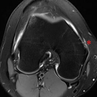
Medial Patellofemoral Ligament Repair
Video, Part 1. Femoral Attachment
1. Ultrasound is used to identify femoral and patellar attachments of medial patellofemoral ligament (MPFL).
2. MPFL is followed from patella to its attachment near adductor tubercle.
3. In-plane ultrasound guidance is used to place needle anterior and distal to tubercle.
4. Percutaneous incision is made down to needle tip. Spear is placed at needle tip for anatomical placement of socket.
5. Socket is drilled.
6. 3.0-mm suture anchor (BioComposite Knotless SutureTak; Arthrex) is placed.
7. Leading edge of torn MPFL is identified.
8. Suture passer (Labral FastPass Scorpion; Arthrex) is used to pass sutures through leading edge of torn MPFL to create horizontal mattress.
9. Sutures are tied.
10. Repair is complete.
Video, Part 2. Patellar Attachment
1. Ultrasound is used to scan patella to identify ideal or exact location of tear. In-plane ultrasound guidance is used to place spinal needle at desired socket location.
2. After spinal needle is positioned, in-line percutaneous incision is made, and needle is palpated at patella.
3. Spear is then placed at spinal needle tip for anatomical positioning of socket.
4. Socket is drilled.
5. 3.0-mm suture anchor (BioComposite Knotless SutureTak; Arthrex) is placed in socket.
6. Leading edge of torn medial patellofemoral ligament (MPFL) is identified.
7. Suture passer (Labral Past Pass Scorpion; Arthrex) is used to pass suture from anchor in horizontal mattress fashion through leading edge of torn MPFL.
8. Wire with loop (FiberSnare; Arthrex) is used as part of knotless technology to pull suture back through anchor to create knotless fixation.
9. Suture is pulled for appropriate tensioning of tissue.
10. Ultrasound is used to visualize construct to confirm that MPFL tissue abuts anchor and that repair is complete.
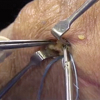
High-Resolution Wireless Ultrasound
Arthrex Synergy MSK Ultrasound by Clarius(http://www.synergy-ultrasound.com/)
Three scanners are capable of targeting different tissue types and depths. We prefer the Synergy MSK Linear Ultrasound by Clarius, a linear transducer that can evaluate tissue to depths of 7 cm and use frequencies from 4 MHz to 13 MHz. Its battery holds a standby charge for 7 days and can be actively used for 45 minutes. The unit has a magnesium shell; with the battery removed, the unit can be completely immersed in liquid without being damaged, which allows for easy cleaning and, potentially, sterilization with a soak solution. Color Doppler (for blood-flow assessment) and proprietary advanced needle visualization technology will be available in June.
The app is simply controlled with typical smart-device gestures. Depth control requires a finger swipe, and zoom takes a pinch. Other controls, such as optimal gain and frequency settings, are automated. Images and videos can be stored on the device and uploaded either to the Clarius Cloud or to a PACS (picture archiving and communication system) device. New features will allow the device to use a Synergy arthroscopy tower (Arthrex) as its display for surgeons and anesthesiologists in the surgical suite.
This technology finally allows ultrasound to be used in the operating room without the hassles of cumbersome machines and the potential contamination by the sleeves covering the cord that connects the transducer and the base unit (Figure 1). 
Recent studies have demonstrated new ultrasound-guided surgical techniques for biceps tenodesis,4 anterolateral ligament reconstruction,13 medial patellofemoral ligament repair or reconstruction,14 and medial collateral ligament internal bracing.4
This small device can also be easily used on sports fields, as it can be carried in a pocket with a smart phone or tablet. With its 10- to 15-second start-up, it is readily available and allows for immediate evaluation of a player. No longer does a player need to be taken off the field for a radiograph. The same advantage of portability means the unit is appropriate for emergency department physicians and staff. 
Surgical pearl: Overall, ultrasound is an imaging technology that has improved the accuracy and efficacy of injections. Wireless capability, portability, and versatility with high-resolution images improve this modality further and extend our reach into surgical, office, hospital, and sports settings. The ease, convenience, and reasonable price of high-resolution wireless ultrasound make it an attractive tool for physicians, nursing staff, athletic trainers, and physical therapists.
1. Eustace JA, Brophy DP, Gibney RP, Bresnihan B, FitzGerald O. Comparison of the accuracy of steroid placement with clinical outcome in patients with shoulder symptoms. Ann Rheum Dis. 1997;56(1):59-63.
2. Finnoff JT, Hall MM, Adams E, et al. American Medical Society for Sports Medicine (AMSSM) position statement: interventional musculoskeletal ultrasound in sports medicine. Br J Sports Med. 2015;49(3):145-150.
3. Henkus HE, Cobben LP, Coerkamp EG, Nelissen RG, van Arkel ER. The accuracy of subacromial injections: a prospective randomized magnetic resonance imaging study. Arthroscopy. 2006;22(3):277-282.
4. Hirahara AM, Panero AJ. A guide to ultrasound of the shoulder, part 3: interventional and procedural uses. Am J Orthop. 2016;45(7):440-445.
5. Kang MN, Rizio L, Prybicien M, Middlemas DA, Blacksin MF. The accuracy of subacromial corticosteroid injections: a comparison of multiple methods. J Shoulder Elbow Surg. 2008;17(1 suppl):61S-66S.
6. Naredo E, Cabero F, Beneyto P, et al. A randomized comparative study of short term response to blind injection versus sonographic-guided injection of local corticosteroids in patients with painful shoulder. J Rheumatol. 2004;31(2):308-314.
7. Panero AJ, Hirahara AM. A guide to ultrasound of the shoulder, part 2: the diagnostic evaluation. Am J Orthop. 2016;45(4):233-238.
8. Partington PF, Broome GH. Diagnostic injection around the shoulder: hit and miss? A cadaveric study of injection accuracy. J Shoulder Elbow Surg. 1998;7(2):147-150.
9. Rutten MJ, Maresch BJ, Jager GJ, de Waal Malefijt MC. Injection of the subacromial-subdeltoid bursa: blind or ultrasound-guided? Acta Orthop. 2007;78(2):254-257.
10. Sethi PM, El Attrache N. Accuracy of intra-articular injection of the glenohumeral joint: a cadaveric study. Orthopedics. 2006;29(2):149-152.
11. Sivan M, Brown J, Brennan S, Bhakta B. A one-stop approach to the management of soft tissue and degenerative musculoskeletal conditions using clinic-based ultrasonography. Musculoskeletal Care. 2011;9(2):63-68.
12. Yamakado K. The targeting accuracy of subacromial injection to the shoulder: an arthrographic evaluation. Arthroscopy. 2002;18(8):887-891.
13. Hirahara AM, Andersen WJ. Ultrasound-guided percutaneous reconstruction of the anterolateral ligament: surgical technique and case report. Am J Orthop. 2016;45(7):418-422, 460.
14. Hirahara AM, Andersen WJ. Ultrasound-guided percutaneous repair of the medial patellofemoral ligament: surgical technique and outcomes. Am J Orthop. In press.
Arthrex Synergy MSK Ultrasound by Clarius(http://www.synergy-ultrasound.com/)
Three scanners are capable of targeting different tissue types and depths. We prefer the Synergy MSK Linear Ultrasound by Clarius, a linear transducer that can evaluate tissue to depths of 7 cm and use frequencies from 4 MHz to 13 MHz. Its battery holds a standby charge for 7 days and can be actively used for 45 minutes. The unit has a magnesium shell; with the battery removed, the unit can be completely immersed in liquid without being damaged, which allows for easy cleaning and, potentially, sterilization with a soak solution. Color Doppler (for blood-flow assessment) and proprietary advanced needle visualization technology will be available in June.
The app is simply controlled with typical smart-device gestures. Depth control requires a finger swipe, and zoom takes a pinch. Other controls, such as optimal gain and frequency settings, are automated. Images and videos can be stored on the device and uploaded either to the Clarius Cloud or to a PACS (picture archiving and communication system) device. New features will allow the device to use a Synergy arthroscopy tower (Arthrex) as its display for surgeons and anesthesiologists in the surgical suite.
This technology finally allows ultrasound to be used in the operating room without the hassles of cumbersome machines and the potential contamination by the sleeves covering the cord that connects the transducer and the base unit (Figure 1).
Recent studies have demonstrated new ultrasound-guided surgical techniques for biceps tenodesis,4 anterolateral ligament reconstruction,13 medial patellofemoral ligament repair or reconstruction,14 and medial collateral ligament internal bracing.4
This small device can also be easily used on sports fields, as it can be carried in a pocket with a smart phone or tablet. With its 10- to 15-second start-up, it is readily available and allows for immediate evaluation of a player. No longer does a player need to be taken off the field for a radiograph. The same advantage of portability means the unit is appropriate for emergency department physicians and staff.
Surgical pearl: Overall, ultrasound is an imaging technology that has improved the accuracy and efficacy of injections. Wireless capability, portability, and versatility with high-resolution images improve this modality further and extend our reach into surgical, office, hospital, and sports settings. The ease, convenience, and reasonable price of high-resolution wireless ultrasound make it an attractive tool for physicians, nursing staff, athletic trainers, and physical therapists.
1. Eustace JA, Brophy DP, Gibney RP, Bresnihan B, FitzGerald O. Comparison of the accuracy of steroid placement with clinical outcome in patients with shoulder symptoms. Ann Rheum Dis. 1997;56(1):59-63.
2. Finnoff JT, Hall MM, Adams E, et al. American Medical Society for Sports Medicine (AMSSM) position statement: interventional musculoskeletal ultrasound in sports medicine. Br J Sports Med. 2015;49(3):145-150.
3. Henkus HE, Cobben LP, Coerkamp EG, Nelissen RG, van Arkel ER. The accuracy of subacromial injections: a prospective randomized magnetic resonance imaging study. Arthroscopy. 2006;22(3):277-282.
4. Hirahara AM, Panero AJ. A guide to ultrasound of the shoulder, part 3: interventional and procedural uses. Am J Orthop. 2016;45(7):440-445.
5. Kang MN, Rizio L, Prybicien M, Middlemas DA, Blacksin MF. The accuracy of subacromial corticosteroid injections: a comparison of multiple methods. J Shoulder Elbow Surg. 2008;17(1 suppl):61S-66S.
6. Naredo E, Cabero F, Beneyto P, et al. A randomized comparative study of short term response to blind injection versus sonographic-guided injection of local corticosteroids in patients with painful shoulder. J Rheumatol. 2004;31(2):308-314.
7. Panero AJ, Hirahara AM. A guide to ultrasound of the shoulder, part 2: the diagnostic evaluation. Am J Orthop. 2016;45(4):233-238.
8. Partington PF, Broome GH. Diagnostic injection around the shoulder: hit and miss? A cadaveric study of injection accuracy. J Shoulder Elbow Surg. 1998;7(2):147-150.
9. Rutten MJ, Maresch BJ, Jager GJ, de Waal Malefijt MC. Injection of the subacromial-subdeltoid bursa: blind or ultrasound-guided? Acta Orthop. 2007;78(2):254-257.
10. Sethi PM, El Attrache N. Accuracy of intra-articular injection of the glenohumeral joint: a cadaveric study. Orthopedics. 2006;29(2):149-152.
11. Sivan M, Brown J, Brennan S, Bhakta B. A one-stop approach to the management of soft tissue and degenerative musculoskeletal conditions using clinic-based ultrasonography. Musculoskeletal Care. 2011;9(2):63-68.
12. Yamakado K. The targeting accuracy of subacromial injection to the shoulder: an arthrographic evaluation. Arthroscopy. 2002;18(8):887-891.
13. Hirahara AM, Andersen WJ. Ultrasound-guided percutaneous reconstruction of the anterolateral ligament: surgical technique and case report. Am J Orthop. 2016;45(7):418-422, 460.
14. Hirahara AM, Andersen WJ. Ultrasound-guided percutaneous repair of the medial patellofemoral ligament: surgical technique and outcomes. Am J Orthop. In press.