Olecranon fractures are relatively common in adults and constitute 10% of all upper extremity injuries.1,2 An olecranon fracture may be sustained either directly (from blunt trauma or a fall onto the tip of the elbow) or indirectly (as a result of forceful hyperextension of the triceps during a fall onto an outstretched arm). Displaced olecranon fractures with extensor discontinuity require reduction and stabilization. One treatment option is tension band wiring (TBW), which is used to manage noncomminuted fractures.3 TBW, first described by Weber and Vasey4 in 1963, involves transforming the distractive forces of the triceps into dynamic compression forces across the olecranon articular surface using 2 intramedullary Kirschner wires (K-wires) and stainless steel wires looped in figure-of-8 fashion.
Various modifications of the TBW technique of Weber and Vasey4 have been proposed to reduce the frequency of complications. These modifications include substituting screws for K-wires, aiming the angle of the K-wires into the anterior coronoid cortex or loop configuration of the stainless steel wire, using double knots and twisting procedures to finalize fixation, and using alternative materials for the loop construct.5-8 In the literature and in our experience, patients often complain after surgery about prominent K-wires and the twisted knots used to tension the construct.9-12 Surgeons also must address the technical difficulties of positioning the brittle wire without kinking, and avoiding slack while tensioning.
In this article, we report on the clinical outcomes of a series of 7 patients with olecranon fracture treated with a US Food and Drug Administration–approved novel isoelastic ultrahigh-molecular-weight polyethylene (UHMWPE) cerclage cable (Iso-Elastic Cerclage System, Kinamed).
Materials and Methods
Surgical Technique
The patient is arranged in a sloppy lateral position to allow access to the posterior elbow. A nonsterile tourniquet is placed on the upper arm, and the limb is sterilely prepared and draped in standard fashion. A posterolateral incision is made around the olecranon and extended proximally 6 cm and distally 6 cm along the subcutaneous border of the ulna. The fracture is visualized and comminution identified.
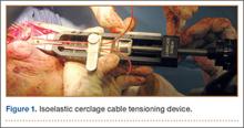
To provide anchorage for a pointed reduction clamp, the surgeon drills a 2.5-mm hole in the subcutaneous border of the ulnar shaft. The fracture is reduced in extension and the clamp affixed. The elbow is then flexed and the reduction confirmed visually and by imaging. After realignment of the articular surfaces, 2 longitudinal, parallel K-wires (diameter, 1.6-2.0 mm) are passed in antegrade direction through the proximal olecranon within the medullary canal of the shaft. The proximal ends must not cross the cortex so they may fully capture the figure-of-8 wire during subsequent, final advancement, and the distal ends must not pierce the anterior cortex. A 2.5-mm transverse hole is created distal to the fracture in the dorsal aspect of the ulnar shaft from medial to lateral at 2 times the distance from the tip of the olecranon to the fracture site. This hole is expanded with a 3.5-mm drill bit, allowing both strands of the cable to be passed simultaneously medial to lateral, making the figure-of-8. The 3.5-mm hole represents about 20% of the overall width of the bone, which we have not found to create a significant stress riser in either laboratory or clinical tests of this construct. Proximally, the cables are placed on the periosteum of the olecranon but deep to the triceps tendon and adjacent to the K-wires. The locking clip is placed on the posterolateral aspect of the elbow joint in a location where it can be covered with local tissue for adequate padding. The cable is then threaded through the clamping bracket and tightened slowly and gradually with a tensioning device to low torque level (Figure 1). At this stage, tension may be released to make any necessary adjustments. Last, the locking clip is deployed, securing the tension band in the clip, and the excess cable is trimmed with a scalpel. Softening and pliability of the cable during its insertion and tensioning should be noted.
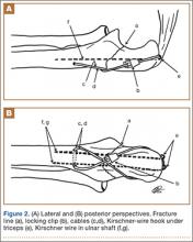
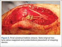
The ends of the K-wires are now curved in a hook configuration. The tines of the hooks should be parallel to accommodate the cable, and then the triceps is sharply incised to bone. If the bone is hard, an awl is used to create a pilot hole so the hook may be impaled into bone while capturing the cable. Next, the triceps is closed over the pins, minimizing the potential for pin migration and backout. The 2 K-wires are left in place to keep the fragments in proper anatomical alignment during healing and to prevent displacement with elbow motion. Figure 2 is a schematic of the final construct, and Figure 3 shows the construct in a patient.


