Augmentation mammaplasty, otherwise known as a breast augmentation, is one of the most common cosmetic procedures performed in cisgender females. Gynecologists routinely perform annual breast examinations and order screening mammography in cisgender women with breast implants. Similarly, there is an increasing number of transgender women seeking breast augmentation – with approximately 60%-70% of patients having desired or undergone the procedure.1 Consequently, these patients are instructed by their surgeons to follow up with gynecologists for annual examinations and screening. While there are many similarities in technique and procedure, there are nuances in patient demographics, anatomy, and surgical technique that obstetricians/gynecologists should be aware of when examining these patients or prior to referring them to a surgeon for augmentation.2
Many patients who are dissatisfied with breast size from hormone therapy alone will seek out augmentation mammaplasty. In patients taking estrogen for hormone therapy, breast growth will commence around 2-3 months and peak over 1-2 years.3 Unlike chest surgery for transmasculine individuals, it is recommended that transfeminine patients seeking breast augmentation wait a minimum of 12 months before to surgery to allow for maximum breast enlargement. As with breast growth in cisgender females, the extent of breast development is multifactorial and varies from individual to individual. Current literature does not suggest that estrogen type or dose affects the ultimate breast size; however, younger age, tissue sensitivity, and body weight may affect breast volume.3 Referral to a genetic counselor and preoperative imaging may be necessary if a patient has a history concerning for a genetic or familial predisposition to breast cancer.
Dr. K. Ashley Brandt
Implant selection and placement is determined by a variety of factors. While the overall principles of augmentation mammaplasty are essentially the same, there are anatomic differences in transfeminine patients that surgeons must take into consideration at the time of the consultation and during the surgery itself. For example, the pectoralis major muscle is more defined, there is a longer sternal notch-to-nipple distance, the chest wall is broader and more barrel-shaped, and there is a shorter distance between the nipple and the inframammary crease.2-4 As a result of the broader chest wall, it is extremely difficult to achieve central cleavage even with larger implant selection. The surgeon must also ensure that the nipple and areola overlie the implant centrally. Medial placement of the implant will result in lateral displacement of the nipples, which can have an unsatisfactory cosmetic appearance.
Incision location can be axillary, inframammary, or even transareolar, although the latter is less common due to the smaller areolar size and larger implant choice.3 If the inframammary incision is used, it should be placed lower than the natural inframammary fold because the distance between the inferior areolar margin and inframammary fold is shorter and will expand after the implant is placed.4 While both saline and silicone implants are available, many surgeons (myself included), favor more form-stable silicone implants. Given the association between anaplastic large-cell lymphoma and textured implants, many surgeons also use nontextured, or smooth, cohesive gel silicone implants.5
Pocket selection of the implant itself can be subglandular – directly under the breast mound – or subpectoral – behind the pectoralis muscle. For patients with a pinch test of greater than 1.5 cm (outside of the area of the breast bud), good skin softening, and marked pectoralis hypertrophy, subglandular placement is reasonable.6 In thin patients with minimal breast development, subglandular placement can result in a “double-mound” appearance and can lead to visible implant edges on the periphery.6 Use of the subpectoral plane is more common and is associated with less implant visibility due to an increased amount of soft-tissue coverage and has lower rates of capsular contracture.4 However, due to the more robust pectoralis muscle in transfeminine patients, implant displacement can occur more frequently compared to subglandular placement. The surgeon and patient must have a thorough discussion about the location of the incision, implant material, and pocket placement along with the benefits and complications of the surgical plan.
Complications of augmentation mammaplasty are rare. However, when they occur it can include capsular contracture, breast asymmetry, hematoma formation, loss of nipple sensation, implant malposition, implant displacement below the inframammary crease, implant rupture, and need for revisional surgery.7 If an obstetrician/gynecologist observes any of the aforementioned findings in a postoperative patient, consultation and referral to a plastic surgeon is imperative.
Postoperative assessment and screening are mandatory in all patients who undergo breast augmentation. It is important for the gynecologist to note the incision placement, know the type of implant used (saline or silicone), and delineate where the implant was placed. If silicone implants are used, breast MRI is more sensitive in detecting implant rupture compared to mammography alone. Given the relatively poor epidemiologic data on breast cancer in transgender women, the Endocrine Society recommends that these patients follow the same screening guidelines as cisgender women.4,6
Dr. Brandt is an ob.gyn. and fellowship-trained gender-affirming surgeon in West Reading, Pa.
Acute dyspnea, with or without hypoxia, is a common patient presentation in the ED, and can be the result of a myriad of mainly cardiac, pulmonary, and metabolic conditions—many of which are life-threatening. Therefore, it is crucial to determine or narrow the diagnosis promptly and initiate appropriate treatment. Focused ultrasound of the lungs can provide important information that can change a patient’s clinical course within minutes of initial evaluation.
Background
Prior to the 1990s, the lung was considered unsuitable for evaluation by ultrasound given the scatter of the ultrasound beam that is produced by the presence of aerated tissue. Lung pathology, however, produces distinct artifacts and signs on ultrasound that correspond with specific disease patterns.
The Bedside Lung Ultrasound in Emergencies (BLUE) protocol1 was developed by Daniel Lichtenstein, a French intensivist, and published in 2008. The goal of the examination is to improve the speed and precision of identifying common causes of acute dyspnea. The sensitivity of ultrasoundfor cardiogenic pulmonary edema, asthma/chronic obstructive pulmonary disease (COPD), and pneumothorax were reported as exceeding 88%.2 Strictly speaking, the BLUE protocol includes an evaluation of the deep veins as well to exclude thrombus; however, this article will focus on ultrasound imaging of the lung.
Relevant Findings
A-line Artifact
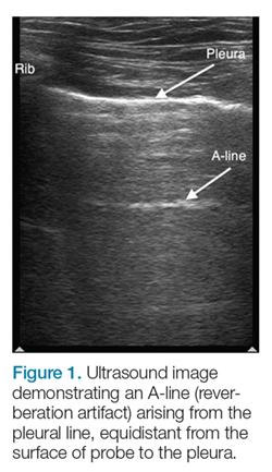
The A-line seen on lung ultrasound (Figure 1) originates from the pleura and can be seen in a normal lung.
Figure 1.Multiple A-lines can exist, and will be spaced at regular intervals corresponding to the depth between the chest wall and pleural line. When A-lines are present in a patient with respiratory distress, and there is no lung sliding (back and forth horizontal movement at the pleural line), pneumothorax, extrapulmonary disease, and uncommon pulmonary conditions should be considered.
B-line Artifact
B-lines, also referred to as “lung rockets,” are a comet-tail artifact arising from the pleura (Figure 2).
Figure 2.In their pathological form, B-lines occur as three or more lines, or are confluent, erase A-lines, and reach a depth of 13 to 15 cm. If lung sliding is also present, B-lines will move with it.
Lung Profiles
A patient can have one of three predominant lung profiles: A-profile, B-profile, or AB-profile.
A-profile.A-lines appear bilaterally with lung sliding in the anterior surface of lungs, suggestive of COPD, or pulmonary embolism. Exacerbation of congestive heart failure can be ruled out.
B-profile. The appearance of prominent B-lines bilaterally, suggestive of heart failure, essentially rules out COPD, pulmonary embolism, and pneumothorax.
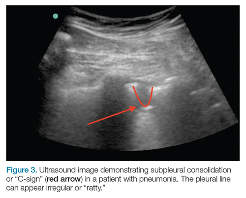
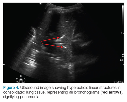
AB-profile.The appearance of predominant B-lines on one lung and predominant A-lines on the other lung, is consistent with an AB profile. This is usually associated with unilateral pneumonia, especially if seen with other findings such as subpleural consolidation (Figure 3) and air bronchograms (Figure 4).
Figure 3.
Figure 4.
Lung Point
The lung point sign is the only specific finding in the BLUE protocol, and signifies the limits of a pneumothorax by showing the interface between normal lung sliding and the edge of the pneumothorax. Without a specific search for the lung point, it may not be seen in the anterior assessment of lung sliding, although lung sliding will still be abolished.
Figure 5.On the left side, the heart may cause the appearance of a false-positive lung point. Normal lung will show the “seashore sign” (Figure 5) on M-mode.
Imaging Technique
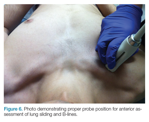
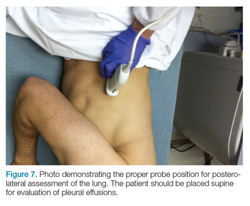
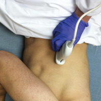
The mid-to-high frequency phased array transducer is used to examine the anterior and posterolateral chest. The original BLUE protocol assesses three zones, but the most relevant information can be obtained from performing the ultrasound in the anterior and posterolateral locations (Figures 6 and 7).
Figure 6.
Figure 7.
Anterior Pleural Assessment
The first step is to evaluate the pleural line anteriorly (Figure 1) for lung sliding. This is best accomplished by setting the depth to no more than 5 cm so that the focal zone of the ultrasound beam is directed at the pleural line, and it is centered on the screen. If no sliding is present, it is because the visceral and parietal pleura are not apposed to one another. There are many pathological entities that can cause this finding, but one of the more common is pneumothorax.
After evaluating the pleural line, the depth will then need to be switched to 15 cm to evaluate for B-lines. If B-lines are present without lung sliding, pneumonia should be strongly considered. The appearance of B-lines with lung sliding signifies alveolar interstitial fluid, commonly from pulmonary edema.
Posterolateral Assessment
The posterolateral assessment (Figure 7) evaluates for pleural effusion and consolidation. The dome of the diaphragm is the landmark above which abnormal lung and artifacts will be seen.
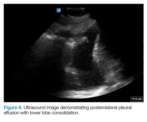
Figure 8.Effusions appear as anechoic (black) collections, adjacent to atelectatic lung, from alveolar consolidation (Figure 8). Pneumonia and parapneumonic effusion can give this appearance, but other causes of pleural effusion will have a similar appearance.
Summary
Lung ultrasound can help narrow the differential diagnosis for acute dyspnea within the first few minutes of the patient encounter. The BLUE protocol provides an organized approach to this evaluation. Often, the protocol is combined with focused examinations of the heart, inferior vena cava, and/or deep veins to complete the clinical picture. It is important to keep in mind that patients may have two or more pathological conditions (eg, asthma and pneumonia) that can affect the ultrasound findings. For this reason, ultrasound interpretation should always occur in the context of the clinical condition. If it does not exclude important diagnoses, additional investigations such as plain radiography, cross-sectional imaging, or ventilation/perfusion studies should be pursued.
References
1. Lichtenstein DA. BLUE-protocol and FALLS-protocol: two applications of lung ultrasound in the critically ill. Chest. 2015;147(6):1659-1670. doi:10.1378/chest.14-1313.
2. Lichtenstein DA, Mezière GA. Relevance of lung ultrasound in the diagnosis of acute respiratory failure: the BLUE protocol. Chest. 2008;134(1):117-125. doi:10.1378/chest.07-2800.
Lung ultrasound using the BLUE protocol provides critical information within minutes of initial evaluation.
Lung ultrasound using the BLUE protocol provides critical information within minutes of initial evaluation.
Acute dyspnea, with or without hypoxia, is a common patient presentation in the ED, and can be the result of a myriad of mainly cardiac, pulmonary, and metabolic conditions—many of which are life-threatening. Therefore, it is crucial to determine or narrow the diagnosis promptly and initiate appropriate treatment. Focused ultrasound of the lungs can provide important information that can change a patient’s clinical course within minutes of initial evaluation.
Background
Prior to the 1990s, the lung was considered unsuitable for evaluation by ultrasound given the scatter of the ultrasound beam that is produced by the presence of aerated tissue. Lung pathology, however, produces distinct artifacts and signs on ultrasound that correspond with specific disease patterns.
The Bedside Lung Ultrasound in Emergencies (BLUE) protocol1 was developed by Daniel Lichtenstein, a French intensivist, and published in 2008. The goal of the examination is to improve the speed and precision of identifying common causes of acute dyspnea. The sensitivity of ultrasoundfor cardiogenic pulmonary edema, asthma/chronic obstructive pulmonary disease (COPD), and pneumothorax were reported as exceeding 88%.2 Strictly speaking, the BLUE protocol includes an evaluation of the deep veins as well to exclude thrombus; however, this article will focus on ultrasound imaging of the lung.
Relevant Findings
A-line Artifact
The A-line seen on lung ultrasound (Figure 1) originates from the pleura and can be seen in a normal lung.
Figure 1.Multiple A-lines can exist, and will be spaced at regular intervals corresponding to the depth between the chest wall and pleural line. When A-lines are present in a patient with respiratory distress, and there is no lung sliding (back and forth horizontal movement at the pleural line), pneumothorax, extrapulmonary disease, and uncommon pulmonary conditions should be considered.
B-line Artifact
B-lines, also referred to as “lung rockets,” are a comet-tail artifact arising from the pleura (Figure 2).
Figure 2.In their pathological form, B-lines occur as three or more lines, or are confluent, erase A-lines, and reach a depth of 13 to 15 cm. If lung sliding is also present, B-lines will move with it.
Lung Profiles
A patient can have one of three predominant lung profiles: A-profile, B-profile, or AB-profile.
A-profile.A-lines appear bilaterally with lung sliding in the anterior surface of lungs, suggestive of COPD, or pulmonary embolism. Exacerbation of congestive heart failure can be ruled out.
B-profile. The appearance of prominent B-lines bilaterally, suggestive of heart failure, essentially rules out COPD, pulmonary embolism, and pneumothorax.
AB-profile.The appearance of predominant B-lines on one lung and predominant A-lines on the other lung, is consistent with an AB profile. This is usually associated with unilateral pneumonia, especially if seen with other findings such as subpleural consolidation (Figure 3) and air bronchograms (Figure 4).
Figure 3.
Figure 4.
Lung Point
The lung point sign is the only specific finding in the BLUE protocol, and signifies the limits of a pneumothorax by showing the interface between normal lung sliding and the edge of the pneumothorax. Without a specific search for the lung point, it may not be seen in the anterior assessment of lung sliding, although lung sliding will still be abolished.
Figure 5.On the left side, the heart may cause the appearance of a false-positive lung point. Normal lung will show the “seashore sign” (Figure 5) on M-mode.
Imaging Technique
The mid-to-high frequency phased array transducer is used to examine the anterior and posterolateral chest. The original BLUE protocol assesses three zones, but the most relevant information can be obtained from performing the ultrasound in the anterior and posterolateral locations (Figures 6 and 7).
Figure 6.
Figure 7.
Anterior Pleural Assessment
The first step is to evaluate the pleural line anteriorly (Figure 1) for lung sliding. This is best accomplished by setting the depth to no more than 5 cm so that the focal zone of the ultrasound beam is directed at the pleural line, and it is centered on the screen. If no sliding is present, it is because the visceral and parietal pleura are not apposed to one another. There are many pathological entities that can cause this finding, but one of the more common is pneumothorax.
After evaluating the pleural line, the depth will then need to be switched to 15 cm to evaluate for B-lines. If B-lines are present without lung sliding, pneumonia should be strongly considered. The appearance of B-lines with lung sliding signifies alveolar interstitial fluid, commonly from pulmonary edema.
Posterolateral Assessment
The posterolateral assessment (Figure 7) evaluates for pleural effusion and consolidation. The dome of the diaphragm is the landmark above which abnormal lung and artifacts will be seen.
Figure 8.Effusions appear as anechoic (black) collections, adjacent to atelectatic lung, from alveolar consolidation (Figure 8). Pneumonia and parapneumonic effusion can give this appearance, but other causes of pleural effusion will have a similar appearance.
Summary
Lung ultrasound can help narrow the differential diagnosis for acute dyspnea within the first few minutes of the patient encounter. The BLUE protocol provides an organized approach to this evaluation. Often, the protocol is combined with focused examinations of the heart, inferior vena cava, and/or deep veins to complete the clinical picture. It is important to keep in mind that patients may have two or more pathological conditions (eg, asthma and pneumonia) that can affect the ultrasound findings. For this reason, ultrasound interpretation should always occur in the context of the clinical condition. If it does not exclude important diagnoses, additional investigations such as plain radiography, cross-sectional imaging, or ventilation/perfusion studies should be pursued.
References
1. Lichtenstein DA. BLUE-protocol and FALLS-protocol: two applications of lung ultrasound in the critically ill. Chest. 2015;147(6):1659-1670. doi:10.1378/chest.14-1313.
2. Lichtenstein DA, Mezière GA. Relevance of lung ultrasound in the diagnosis of acute respiratory failure: the BLUE protocol. Chest. 2008;134(1):117-125. doi:10.1378/chest.07-2800.
Evaluating pediatric patients presenting to the ED with head trauma can be a challenging task for emergency physicians (EPs). Specifically, identifying a nondisplaced skull fracture is not always possible through physical examination alone.1 However, point-of-care (POC) ultrasound permits rapid identification of skull fractures, which in turn assists the EP to determine if advanced imaging studies such as computed tomography (CT) are necessary.
Case
A previously healthy 10-month-old male infant presented to the ED with his mother for evaluation of rhinorrhea, cough, and fever, the onset of which began 24 hours prior to presentation. The patient’s mother reported that the infant continually tugged at his right ear throughout the previous evening and was increasingly irritable, but not inconsolable.
Initial vital signs at presentation were: blood pressure, 95/54 mm Hg; heart rate, 146 beats/min; respiratory rate, 36 beats/min, and temperature, 101.8°F. Oxygen saturation was 96% on room air. The physical examination was notable for an alert well-appearing infant who had a tender nonecchymotic scalp hematoma superior to the right pinna, clear tympanic membranes, crusted mucous bilaterally at the nares, nonlabored respirations, and wheezing throughout the lung fields.
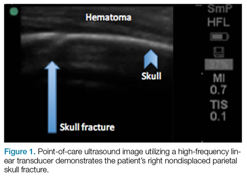
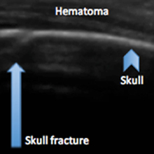
Figure 1.A POC ultrasound scan performed over the hematoma demonstrated a right nondisplaced parietal skull fracture (Figure 1).
Imaging Technique
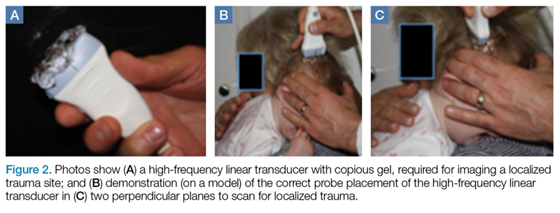
To evaluate for skull fractures using POC ultrasound, the area of localized trauma must first be identified.2,3 Evidence of trauma includes an area of focal tenderness, abrasion, soft-tissue swelling, and hematoma.2,3 The presence of any depressed and open cranial injuries are contraindications to ultrasound. In which case, a physician should consult a neurosurgical specialist and obtain a CT scan of the head.
A high-frequency linear probe (5-10 MHz) is used to scan the area of localized trauma; this should be performed in two perpendicular planes using copious gel and light pressure (Figures 2a-2c).
Figure 2.Skull fracture on ultrasound will appear as a cortical irregularity that is distinguishable from normal skull suture lines. If a cortical disruption is identified, the contralateral side should be scanned to distinguish the fracture from skull suture lines.2 Suture lines can be distinguished from a nondisplaced fracture because suture lines can be followed back to the associated fontanelle.3
Discussion
Closed head trauma is one of the most common pediatric injuries, accounting for roughly 1.4 million ED visits annually in the United States.5 Four to 12% percent of these minor traumas result in an intracranial injury,2 and the presence of a skull fracture is associated with a 4- to 20-fold increase in risk of underlying intracranial hemorrhage.3
Clinical assessment alone is not always reliable in predicting skull fracture and intracranial injury, especially in children younger than 2 years of age.2,3 Ultrasound is safe, noninvasive, expedient, cost-effective, and well tolerated in the pediatric population for identifying skull fractures,3 and can obviate the need for skull radiographs4 or procedural sedation. Moreover, POC ultrasound can serve as an adjunct to the Pediatric Emergency Care Applied Research Network head injury algorithm for head CT use decision rules if the fracture is not palpable on examination.
Several prospective studies and case reports have demonstrated the usefulness of POC ultrasound in diagnosing pediatric skull fractures in the ED.1-4 Two of the four cases published represented cases in which the EP identified an undisclosed nonaccidental trauma through POC ultrasound. Rabiner et al,3 estimates a combined sensitivity and specificity of 94% and 96%, respectively. It is important to remember that intracranial injury can still occur without an associated skull fracture. As our case demonstrates, POC ultrasound is a useful tool in risk-stratifying minor head trauma in children.
Case Conclusion
The head CT study confirmed a nondisplaced, oblique, and acute-appearing linear fracture of the right parietal bone extending from the squamosal to the lambdoid suture. There was no associated intracranial hemorrhage. The patient was admitted to the hospital for a nonaccidental trauma evaluation. The Department of Children and Family Services was contacted and the patient was discharged in the temporary custody of his maternal grandmother.
Summary
Point-of-care ultrasound is a useful diagnostic tool to rapidly evaluate for, and diagnose skull fractures in pediatric patients. Given its high sensitivity and specificity, ultrasound can help EPs identify occult nondisplaced skull fractures in children.
References
1. Riera A, Chen L. Ultrasound evaluation of skull fractures in children: a feasibility study. Pediatr Emerg Care. 2012;28(5):420-425. doi:10.1097/PEC.0b013e318252da3b.
2. Parri N, Crosby BJ, Glass C, et al. Ability of emergency ultrasonography to detect pediatric skull fractures: a prospective, observational study. J Emerg Med. 2013;44(1)135-141.
3. Rabiner JE, Friedman LM, Khine H, Avner JR, Tsung JW. Accuracy of point-of-care ultrasound for diagnosis of skull fractures in children. Pediatrics. 2013;131(6):e1757-1764. doi:10.1542/peds.2012-3921.
4. Ramirez-Schrempp D, Vinci RJ, Liteplo AS. Bedside ultrasound in the diagnosis of skull fractures in the pediatric emergency department. Pediatr Emerg Care. 2011;27(4):312-314. doi:10.1097/PEC.0b013e3182131579.
5. Coronado VG, Xu L, Basavaraju SV, et al; Centers for Disease Control and Prevention (CDC). Surveillance for traumatic brain injury-related deaths--United States, 1997-2007. MMWR Surveill Summ. 2011;60(5):1-32.
Evaluating pediatric patients presenting to the ED with head trauma can be a challenging task for emergency physicians (EPs). Specifically, identifying a nondisplaced skull fracture is not always possible through physical examination alone.1 However, point-of-care (POC) ultrasound permits rapid identification of skull fractures, which in turn assists the EP to determine if advanced imaging studies such as computed tomography (CT) are necessary.
Case
A previously healthy 10-month-old male infant presented to the ED with his mother for evaluation of rhinorrhea, cough, and fever, the onset of which began 24 hours prior to presentation. The patient’s mother reported that the infant continually tugged at his right ear throughout the previous evening and was increasingly irritable, but not inconsolable.
Initial vital signs at presentation were: blood pressure, 95/54 mm Hg; heart rate, 146 beats/min; respiratory rate, 36 beats/min, and temperature, 101.8°F. Oxygen saturation was 96% on room air. The physical examination was notable for an alert well-appearing infant who had a tender nonecchymotic scalp hematoma superior to the right pinna, clear tympanic membranes, crusted mucous bilaterally at the nares, nonlabored respirations, and wheezing throughout the lung fields.
Figure 1.A POC ultrasound scan performed over the hematoma demonstrated a right nondisplaced parietal skull fracture (Figure 1).
Imaging Technique
To evaluate for skull fractures using POC ultrasound, the area of localized trauma must first be identified.2,3 Evidence of trauma includes an area of focal tenderness, abrasion, soft-tissue swelling, and hematoma.2,3 The presence of any depressed and open cranial injuries are contraindications to ultrasound. In which case, a physician should consult a neurosurgical specialist and obtain a CT scan of the head.
A high-frequency linear probe (5-10 MHz) is used to scan the area of localized trauma; this should be performed in two perpendicular planes using copious gel and light pressure (Figures 2a-2c).
Figure 2.Skull fracture on ultrasound will appear as a cortical irregularity that is distinguishable from normal skull suture lines. If a cortical disruption is identified, the contralateral side should be scanned to distinguish the fracture from skull suture lines.2 Suture lines can be distinguished from a nondisplaced fracture because suture lines can be followed back to the associated fontanelle.3
Discussion
Closed head trauma is one of the most common pediatric injuries, accounting for roughly 1.4 million ED visits annually in the United States.5 Four to 12% percent of these minor traumas result in an intracranial injury,2 and the presence of a skull fracture is associated with a 4- to 20-fold increase in risk of underlying intracranial hemorrhage.3
Clinical assessment alone is not always reliable in predicting skull fracture and intracranial injury, especially in children younger than 2 years of age.2,3 Ultrasound is safe, noninvasive, expedient, cost-effective, and well tolerated in the pediatric population for identifying skull fractures,3 and can obviate the need for skull radiographs4 or procedural sedation. Moreover, POC ultrasound can serve as an adjunct to the Pediatric Emergency Care Applied Research Network head injury algorithm for head CT use decision rules if the fracture is not palpable on examination.
Several prospective studies and case reports have demonstrated the usefulness of POC ultrasound in diagnosing pediatric skull fractures in the ED.1-4 Two of the four cases published represented cases in which the EP identified an undisclosed nonaccidental trauma through POC ultrasound. Rabiner et al,3 estimates a combined sensitivity and specificity of 94% and 96%, respectively. It is important to remember that intracranial injury can still occur without an associated skull fracture. As our case demonstrates, POC ultrasound is a useful tool in risk-stratifying minor head trauma in children.
Case Conclusion
The head CT study confirmed a nondisplaced, oblique, and acute-appearing linear fracture of the right parietal bone extending from the squamosal to the lambdoid suture. There was no associated intracranial hemorrhage. The patient was admitted to the hospital for a nonaccidental trauma evaluation. The Department of Children and Family Services was contacted and the patient was discharged in the temporary custody of his maternal grandmother.
Summary
Point-of-care ultrasound is a useful diagnostic tool to rapidly evaluate for, and diagnose skull fractures in pediatric patients. Given its high sensitivity and specificity, ultrasound can help EPs identify occult nondisplaced skull fractures in children.
References
1. Riera A, Chen L. Ultrasound evaluation of skull fractures in children: a feasibility study. Pediatr Emerg Care. 2012;28(5):420-425. doi:10.1097/PEC.0b013e318252da3b.
2. Parri N, Crosby BJ, Glass C, et al. Ability of emergency ultrasonography to detect pediatric skull fractures: a prospective, observational study. J Emerg Med. 2013;44(1)135-141.
3. Rabiner JE, Friedman LM, Khine H, Avner JR, Tsung JW. Accuracy of point-of-care ultrasound for diagnosis of skull fractures in children. Pediatrics. 2013;131(6):e1757-1764. doi:10.1542/peds.2012-3921.
4. Ramirez-Schrempp D, Vinci RJ, Liteplo AS. Bedside ultrasound in the diagnosis of skull fractures in the pediatric emergency department. Pediatr Emerg Care. 2011;27(4):312-314. doi:10.1097/PEC.0b013e3182131579.
5. Coronado VG, Xu L, Basavaraju SV, et al; Centers for Disease Control and Prevention (CDC). Surveillance for traumatic brain injury-related deaths--United States, 1997-2007. MMWR Surveill Summ. 2011;60(5):1-32.
Ankle effusions can be quite debilitating, causing band-like swelling and stiffness to the anterior aspect of ankle at the tibiotalar joint. Significant swelling can impair ankle dorsiflexion and plantar flexion. The differential diagnosis for joint effusions is wide, and includes traumatic effusion; gout; osteoarthritis; rheumatoid arthritis; and septic arthritis, which is one of the most important diagnoses for the emergency physician (EP) to identify and initiate prompt treatment to reduce the risk of serious morbidity and mortality. Differentiating these conditions requires joint aspiration and synovial fluid analysis. While a large effusion will be palpable and likely ballotable, smaller effusions are more challenging clinically. In such cases, point-of-care (POC) ultrasound can be a valuable tool in confirming a joint effusion.
Identifying Landmarks and Tibiotalar Joint
To access the tibiotalar joint space, it is important to identify useful landmarks.1 This is best accomplished by having the patient in the supine position, with the affected knee flexed approximately 90° and plantar surface of the foot lying flat on the bed (Figure 1).
Figure 1.The palpable landmark is the tibialis anterior tendon lateral to the medial malleolus (Figure 2). Immediately lateral and slightly distal to the tibialis anterior is the extensor hallucis longus (EHL) tendon, which extends into the proximal foot.1
Figure 2.When aspirating the ankle joint space, these landmarks will avoid the dorsalis pedis artery lateral to EHL tendon. The location for aspiration of ankle joint will be medial to tibialis anterior tendon.
Performing the Arthrocentesis
The arthrocentesis is performed under sterile conditions using the high-frequency linear probe. A sterile probe cover is highly recommended if the operator will be using ultrasound to guide the procedure in real time.2 Using the palpable landmarks as a guide, the clinician should align the probe just medial to the tibialis anterior tendon with the probe marker oriented cephalad; scanning should begin superior to the ankle joint. The tibia will appear as a hyperechoic stripe just under a thin soft tissue layer. When the tibia is visible, the clinician should then slide the probe distally. The joint space will demonstrated by visualization of the distal tibia and talus bone (Figure 3).
Figure 3.Since bone is highly reflective on ultrasound, the cortex will appear as white echogenic line with dark shadow below it. An effusion will appear as an anaechoic (black) fluid collection in the space between the tibia and talus (Figure 4).
Figure 4.If an effusion is present, the clinician should then center the probe over this space and administer local anesthetic medial to the probe (and tibialis anterior), employing an out-of-plane needle approach. Next, one inserts an 18-gauge needle at an angle of 75° to 80° in relation to the probe (Figure 5).
Figure 5.Using ultrasound to visualize the needle tip entering the effusion, the clinician should aspirate the fluid slowly while advancing the needle into the joint space.
Pearls and Pitfalls
Point-of-care ultrasound is not only useful to guide arthrocentesis of joint effusions, but also to confirm the presence of an effusion prior to aspiration. At our institution, we have had many cases in which POC ultrasound demonstrated an absence of effusion, and we were able to avoid an unnecessary joint aspiration. Moreover, when an effusion is present, POC ultrasound-guided aspiration avoids complications. The use of POC ultrasound can also increase the confidence of the provider performing arthrocentesis of joints less commonly aspirated.
Summary
Joint aspiration is an important procedural tool for EPs, especially when used to rule out life-threatening conditions such as septic arthritis. Deeper joints and small fluid collections, however, can be difficult to access without image guidance. In the ED setting, POC ultrasound provides a widely available, easy-to-use, low-cost tool to increase the likelihood of success while minimizing damage to adjacent structures.
2. Reichman EF, Simon RR. Arthrocentesis. In: Reichman EF, Simon RR, eds. Emergency Medicine Procedures. 2nd ed. McGraw Hill Education: New York, NY; 2013.
Point-of-care ultrasound is a valuable tool to evaluate the presence of joint effusion of the ankle and guide aspiration.
Point-of-care ultrasound is a valuable tool to evaluate the presence of joint effusion of the ankle and guide aspiration.
Ankle effusions can be quite debilitating, causing band-like swelling and stiffness to the anterior aspect of ankle at the tibiotalar joint. Significant swelling can impair ankle dorsiflexion and plantar flexion. The differential diagnosis for joint effusions is wide, and includes traumatic effusion; gout; osteoarthritis; rheumatoid arthritis; and septic arthritis, which is one of the most important diagnoses for the emergency physician (EP) to identify and initiate prompt treatment to reduce the risk of serious morbidity and mortality. Differentiating these conditions requires joint aspiration and synovial fluid analysis. While a large effusion will be palpable and likely ballotable, smaller effusions are more challenging clinically. In such cases, point-of-care (POC) ultrasound can be a valuable tool in confirming a joint effusion.
Identifying Landmarks and Tibiotalar Joint
To access the tibiotalar joint space, it is important to identify useful landmarks.1 This is best accomplished by having the patient in the supine position, with the affected knee flexed approximately 90° and plantar surface of the foot lying flat on the bed (Figure 1).
Figure 1.The palpable landmark is the tibialis anterior tendon lateral to the medial malleolus (Figure 2). Immediately lateral and slightly distal to the tibialis anterior is the extensor hallucis longus (EHL) tendon, which extends into the proximal foot.1
Figure 2.When aspirating the ankle joint space, these landmarks will avoid the dorsalis pedis artery lateral to EHL tendon. The location for aspiration of ankle joint will be medial to tibialis anterior tendon.
Performing the Arthrocentesis
The arthrocentesis is performed under sterile conditions using the high-frequency linear probe. A sterile probe cover is highly recommended if the operator will be using ultrasound to guide the procedure in real time.2 Using the palpable landmarks as a guide, the clinician should align the probe just medial to the tibialis anterior tendon with the probe marker oriented cephalad; scanning should begin superior to the ankle joint. The tibia will appear as a hyperechoic stripe just under a thin soft tissue layer. When the tibia is visible, the clinician should then slide the probe distally. The joint space will demonstrated by visualization of the distal tibia and talus bone (Figure 3).
Figure 3.Since bone is highly reflective on ultrasound, the cortex will appear as white echogenic line with dark shadow below it. An effusion will appear as an anaechoic (black) fluid collection in the space between the tibia and talus (Figure 4).
Figure 4.If an effusion is present, the clinician should then center the probe over this space and administer local anesthetic medial to the probe (and tibialis anterior), employing an out-of-plane needle approach. Next, one inserts an 18-gauge needle at an angle of 75° to 80° in relation to the probe (Figure 5).
Figure 5.Using ultrasound to visualize the needle tip entering the effusion, the clinician should aspirate the fluid slowly while advancing the needle into the joint space.
Pearls and Pitfalls
Point-of-care ultrasound is not only useful to guide arthrocentesis of joint effusions, but also to confirm the presence of an effusion prior to aspiration. At our institution, we have had many cases in which POC ultrasound demonstrated an absence of effusion, and we were able to avoid an unnecessary joint aspiration. Moreover, when an effusion is present, POC ultrasound-guided aspiration avoids complications. The use of POC ultrasound can also increase the confidence of the provider performing arthrocentesis of joints less commonly aspirated.
Summary
Joint aspiration is an important procedural tool for EPs, especially when used to rule out life-threatening conditions such as septic arthritis. Deeper joints and small fluid collections, however, can be difficult to access without image guidance. In the ED setting, POC ultrasound provides a widely available, easy-to-use, low-cost tool to increase the likelihood of success while minimizing damage to adjacent structures.
2. Reichman EF, Simon RR. Arthrocentesis. In: Reichman EF, Simon RR, eds. Emergency Medicine Procedures. 2nd ed. McGraw Hill Education: New York, NY; 2013.
2. Reichman EF, Simon RR. Arthrocentesis. In: Reichman EF, Simon RR, eds. Emergency Medicine Procedures. 2nd ed. McGraw Hill Education: New York, NY; 2013.
Emergency Ultrasound: Tendon Evaluation With Ultrasonography
Ultrasound provides detailed and dynamic assessment of tendons, increasing the diagnostic accuracy of injuries, especially when physical examination is equivocal.
The vast majority of musculotendinous injuries occur secondary to violent contraction or excessive stretching.1 Ligamentous injuries, on the other hand, are due to an abnormal motion of joints. The magnitude of inciting forces results in a spectrum of pathology, ranging from a minor tear to a complete disruption of structures.
Ultrasonography provides a detailed assessment of soft tissue anatomy and dynamic functionality, and in some instances can be comparable or even superior to magnetic resonance imaging2 because the structural characteristics of certain tendons make them ideal for imaging via ultrasonography. We describe some of these characteristics and highlight their utility in diagnostic imaging.
Anatomical Structure
Tendons consist of tightly packed type I collagen fibers forming subfascicles that are arranged in a parallel distribution as fascicles. These bundles are held together by loose soft tissue, and the entire structure is covered by a thick fibroelastic epitendineum sheath. This linear distribution of structures yields a uniquely linear “fibrillary” pattern when viewed along the longitudinal axis of the structure (Figure 1a). In the short-axis view, the tendon appears as a well-circumscribed structure with speckled pattern of hyperechoic foci (Figure 1b). 3
Figure 1
Imaging Technique
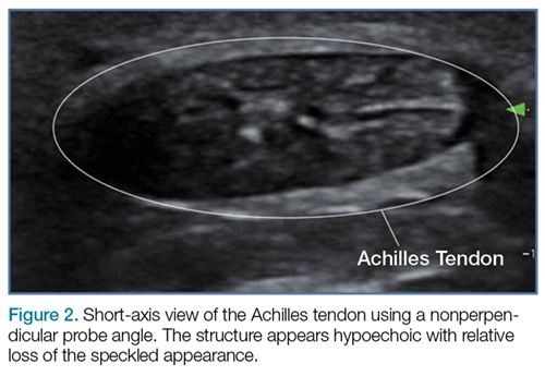
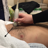
The optimal scanning technique involves the use of a high-frequency linear transducer. Higher frequencies yield more detailed images, but may be limited in patients with deeper structures due to body habitus. A key concept in tendon evaluation is an artifact known as “anisotropy.” This refers to change in appearance of the tendon based on the incident angle of the ultrasound beam. For example, when the probe is held perpendicular to the structure of interest, parallel fibers will reflect the emitted beam toward the probe and thus appear as hyperechoic and speckled, a characteristic of these fibers (Figures1a and 1b). Contrarily, if the probe is held at a nonperpendicular angle, the reflected beam will not return to the probe, resulting in a hypoechoic appearance (Figure 2).
Figure 2
Pathology
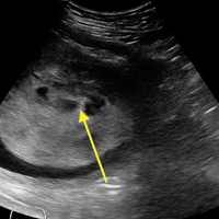
Tendon strains result in varying degrees of fibrous tearing. These tears can range from first-degree tears (a few fibers) to third-degree tears (complete disruption). Partial tears result in focal hematoma formation (Figure 3a) at the region of disruption, appearing on ultrasound as a hypoechoic fluid collection within a hyperechoic fibrillary or speckled tendon structure. If the disruption occurs along the surface of the tendon, a focus of anechoic fluid may be seen surrounding the tendon. Complete tendon ruptures, on the other hand, appear as a hypoechoic void with retracted tendon fragments visualized on either side4 (Figures 3b and 3c). Although complete tears can be more apparent clinically in areas in which a group of tendons performs a cohesive movement (ie, rotator cuff), ultrasound can significantly reduce the rate of delayed diagnosis when physical examination is equivocal.
Figure 3
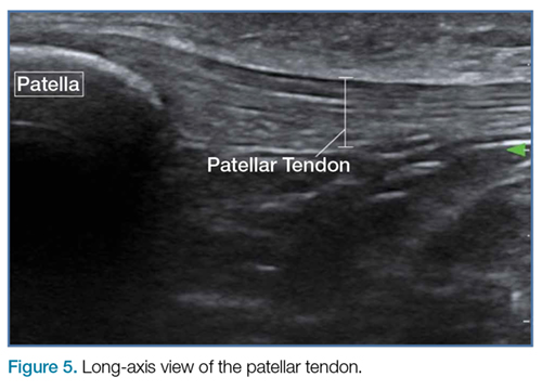
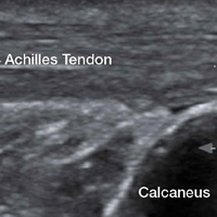
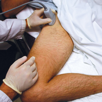
In the appropriate clinical setting, ultrasonography can provide rapid and dynamic assessment of musculotendinous injuries. Lower extremity injuries, including those affecting the Achilles (Figure 1), quadriceps, (Figures4a and 4b) and patellar tendons (Figure 5), are easier clinical applications.
Figure 4
Assessment of rotator cuff tendons, although more difficult, can provide a specific assessment of shoulder pain.5 In such scenarios, ultrasound can serve a very useful role as an adjunct to the physical examination.
Figure 5
An important point to recognize is that tendons will appear hypoechoic at the insertion point on bone (anthesis) due to increased curvature resulting in lack of anisotropy. This can appear as a pathological finding, but can be accounted for by simply performing a heel-toe or tilt maneuver to arrange the beam perpendicular to the tendon fibers (Figures6a and 6b).
Figure 6
Summary
Musculotendinous injuries many times present as nonspecific symptoms of pain and/or swelling. In the case of an equivocal physical examination, musculotendinous injuries can be diagnosed with increased accuracy through the use of ultrasound. Understanding the artifactual component of tendon ultrasound can aid the clinician in diagnosing these injuries, enhancing patient care and satisfaction.
5. Tran G, Hensor EM, Ray A, Kingsbury SR, O’Connor P, Conaghan PG. Ultrasound-detected pathologies cluster into groups with different clinical outcomes: data from 3000 community referrals for shoulder pain. Arthritis Res Ther. 2017;19(1):30. doi:10.1186/s13075-017-1235-y.
Ultrasound provides detailed and dynamic assessment of tendons, increasing the diagnostic accuracy of injuries, especially when physical examination is equivocal.
Ultrasound provides detailed and dynamic assessment of tendons, increasing the diagnostic accuracy of injuries, especially when physical examination is equivocal.
The vast majority of musculotendinous injuries occur secondary to violent contraction or excessive stretching.1 Ligamentous injuries, on the other hand, are due to an abnormal motion of joints. The magnitude of inciting forces results in a spectrum of pathology, ranging from a minor tear to a complete disruption of structures.
Ultrasonography provides a detailed assessment of soft tissue anatomy and dynamic functionality, and in some instances can be comparable or even superior to magnetic resonance imaging2 because the structural characteristics of certain tendons make them ideal for imaging via ultrasonography. We describe some of these characteristics and highlight their utility in diagnostic imaging.
Anatomical Structure
Tendons consist of tightly packed type I collagen fibers forming subfascicles that are arranged in a parallel distribution as fascicles. These bundles are held together by loose soft tissue, and the entire structure is covered by a thick fibroelastic epitendineum sheath. This linear distribution of structures yields a uniquely linear “fibrillary” pattern when viewed along the longitudinal axis of the structure (Figure 1a). In the short-axis view, the tendon appears as a well-circumscribed structure with speckled pattern of hyperechoic foci (Figure 1b). 3
Figure 1
Imaging Technique
The optimal scanning technique involves the use of a high-frequency linear transducer. Higher frequencies yield more detailed images, but may be limited in patients with deeper structures due to body habitus. A key concept in tendon evaluation is an artifact known as “anisotropy.” This refers to change in appearance of the tendon based on the incident angle of the ultrasound beam. For example, when the probe is held perpendicular to the structure of interest, parallel fibers will reflect the emitted beam toward the probe and thus appear as hyperechoic and speckled, a characteristic of these fibers (Figures1a and 1b). Contrarily, if the probe is held at a nonperpendicular angle, the reflected beam will not return to the probe, resulting in a hypoechoic appearance (Figure 2).
Figure 2
Pathology
Tendon strains result in varying degrees of fibrous tearing. These tears can range from first-degree tears (a few fibers) to third-degree tears (complete disruption). Partial tears result in focal hematoma formation (Figure 3a) at the region of disruption, appearing on ultrasound as a hypoechoic fluid collection within a hyperechoic fibrillary or speckled tendon structure. If the disruption occurs along the surface of the tendon, a focus of anechoic fluid may be seen surrounding the tendon. Complete tendon ruptures, on the other hand, appear as a hypoechoic void with retracted tendon fragments visualized on either side4 (Figures 3b and 3c). Although complete tears can be more apparent clinically in areas in which a group of tendons performs a cohesive movement (ie, rotator cuff), ultrasound can significantly reduce the rate of delayed diagnosis when physical examination is equivocal.
Figure 3
In the appropriate clinical setting, ultrasonography can provide rapid and dynamic assessment of musculotendinous injuries. Lower extremity injuries, including those affecting the Achilles (Figure 1), quadriceps, (Figures4a and 4b) and patellar tendons (Figure 5), are easier clinical applications.
Figure 4
Assessment of rotator cuff tendons, although more difficult, can provide a specific assessment of shoulder pain.5 In such scenarios, ultrasound can serve a very useful role as an adjunct to the physical examination.
Figure 5
An important point to recognize is that tendons will appear hypoechoic at the insertion point on bone (anthesis) due to increased curvature resulting in lack of anisotropy. This can appear as a pathological finding, but can be accounted for by simply performing a heel-toe or tilt maneuver to arrange the beam perpendicular to the tendon fibers (Figures6a and 6b).
Figure 6
Summary
Musculotendinous injuries many times present as nonspecific symptoms of pain and/or swelling. In the case of an equivocal physical examination, musculotendinous injuries can be diagnosed with increased accuracy through the use of ultrasound. Understanding the artifactual component of tendon ultrasound can aid the clinician in diagnosing these injuries, enhancing patient care and satisfaction.
5. Tran G, Hensor EM, Ray A, Kingsbury SR, O’Connor P, Conaghan PG. Ultrasound-detected pathologies cluster into groups with different clinical outcomes: data from 3000 community referrals for shoulder pain. Arthritis Res Ther. 2017;19(1):30. doi:10.1186/s13075-017-1235-y.
5. Tran G, Hensor EM, Ray A, Kingsbury SR, O’Connor P, Conaghan PG. Ultrasound-detected pathologies cluster into groups with different clinical outcomes: data from 3000 community referrals for shoulder pain. Arthritis Res Ther. 2017;19(1):30. doi:10.1186/s13075-017-1235-y.
Emergency Ultrasound: Identification of Aortic Dissection Using Limited Bedside Ultrasound
A case involving a 70-year-old woman presenting with acute chest pain highlights the utility of bedside ultrasound in rapidly diagnosing aortic dissection.
The diagnosis of aortic dissection is often challenging due to its various presentations and the frequent absence of classic findings. This high-morbidity and high-mortality condition may present with nonspecific chest, back, or abdominal pain, and is often associated with hypotension.1 Point-of-care (POC) ultrasound in the ED allows for rapid diagnosis of this time-sensitive disease.
Case
A 70-year-old woman presented to the ED for evaluation of acute sharp chest pain, which she stated began while she was exercising earlier that day. The pain was substernal and radiated to her upper back. The patient also described associated lightheadedness and dyspnea, but denied any focal weakness or paresthesias. Her vital signs were remarkable for a blood pressure of 90/31 mm Hg and a heart rate of 42 beats/min. A bedside ultrasound of the patient’s aortic root and abdominal aorta was performed to assess for evidence of aortic dissection.
Figure 1Imaging Technique
To evaluate for aortic dissection using POC ultrasound, views of the aortic root and the abdominal aorta should be obtained with the patient in the supine position. The phased array (cardiac) probe is used to obtain the parasternal long axis (PSLA) view of the heart to visualize the aortic root. The PSLA view is obtained by placing the probe in the third or fourth intercostal space, adjacent to the left sternal border, with the probe parallel to the long axis of the left ventricle (Figure 1). The American Society of Echocardiography recommends measuring the aortic diameter at the sinus of Valsalva, but measurement of the largest visible portion of the aortic root may be more practical.2,3 Measurement of the aortic root diameter should occur at end diastole.2,3 Tricks for better visualization of the aortic root include tilting the probe tail 10° toward the patient’s right elbow (ie, aiming the probe footprint toward the patient’s left shoulder), or placing the patient in the left lateral decubitus position. Values greater than 4 cm indicate aortic root dilatation.4 Figure 2 demonstrates the PSLA view in our patient, showing the dilated aortic root, which measured roughly 5 cm.
Figure 2
The abdominal aorta is best visualized using a low-frequency curvilinear (abdominal) probe. The aorta should be visualized in the transverse plane from the diaphragm to its bifurcation by placing the probe in the epigastrium and slowly moving it inferiorly to the level of the umbilicus (Figure 3). The aorta can then be visualized in the longitudinal plane by rotating the probe clockwise until it is parallel with the long axis of the aorta (Figure 4). Visualization of an intimal flap is the most common sonographic finding associated with an abdominal aortic dissection. In our patient, an intimal flap was visualized in both the transverse and longitudinal views (Figures 5 and 6).
Figure 3
Discussion
Aortic dissection is a medical emergency—one that has a reported in-hospital mortality of 27.4%.1 Therefore, prompt diagnosis of an aortic dissection in the ED is crucial to improving patient outcomes. Traditionally, emergency physicians (EPs) have relied on aortography and contrast-enhanced computed tomography (CT) to diagnose aortic dissection. However, both of these modalities require a considerable length of time, injection of contrast material, and often transportation of the patient from the ED.
Point-of-care ultrasound provides a fast and noninvasive tool for the diagnosis of aortic dissection. Several recent case reports and case series have highlighted the utility of POC ultrasound to diagnose aortic dissection in the ED.5-7
Figure 4
As our case demonstrates, dilatation of the thoracic aorta and the presence of an intimal flap are indicators of aortic dissection. Evaluation of transthoracic and transabdominal ultrasound for aortic dissection shows that aortic root dilatation has a sensitivity of 77% and specificity of 95%, and visualization of an intimal flap has a sensitivity of 67% to 80% and a specificity of 99% to 100%.4,8-11 Therefore, a combination of a bedside transthoracic and transabdominal ultrasound provides a comprehensive bedside evaluation for aortic dissection.
Figure 5
Case Conclusion
After the results of the POC transthoracic and transabdominal ultrasound were reviewed, we promptly consulted the vascular surgery team. They performed a CT scan verifying a DeBakey type I aortic dissection involving both the ascending aorta and the descending aorta. The patient was subsequently taken to the operating room for definitive repair with a graft. She was discharged home on hospital day 9 in good condition.
Figure 6
Summary
Point-of-care ultrasound is a useful bedside tool for the rapid diagnosis of aortic dissection in the ED. The aortic root dilatation seen on the PSLA view and the presence of an intimal flap seen on either transthoracic or transabdominal views of the aorta are both highly sensitive for aortic dissection.
References
1. Hagan PG, Nienaber CA, Isselbacher EM, et al. The International Registry of Acute Aortic Dissection (IRAD): new insights into an old disease. JAMA. 2000;283(7):897-903. 2. Lang RM, Badano LP, Mor-Avi V, et al. Recommendations for cardiac chamber quantification by echocardiography in adults: an update from the American Society of Echocardiography and the European Association of Cardiovascular Imaging. Eur Heart J Cardiovasc Imaging. 2015;16(3):233-270. doi:10.1093/ehjci/jev014. 3. Strayer RJ, Shearer PL, Hermann LK. Screening, evaluation, and early management of acute aortic dissection in the ED. Curr Cardiol Rev. 2012;8(2):152-157. 4. Taylor RA, Oliva I, Van Tonder R, Elefteriades J, Dziura J, Moore CL. Point-of-care focused cardiac ultrasound for the assessment of thoracic aortic dimensions, dilation, and aneurysmal disease. Acad Emerg Med. 2012;19(2):244-247. doi:10.1111/j.1553-2712.2011.01279.x. 5. Williams J, Heiner JD, Perreault MD, McArthur TJ. Aortic dissection diagnosed by ultrasound. West J Emerg Med. 2010;11(1):98-99. 6. Blaivas M, Sierzenski PR. Dissection of the proximal thoracic aorta: a new ultrasonographic sign in the subxiphoid view. Am J Emerg Med. 2002;20(4):344-348. 7. Perkins AM, Liteplo A, Noble VE. Ultrasound diagnosis of type a aortic dissection. J Emerg Med. 2010;38(4):490-493. doi:10.1016/j.jemermed.2008.05.013. 8. Fojtik JP, Costantino TG, Dean AJ. The diagnosis of aortic dissection by emergency medicine ultrasound. J Emerg Med. 2007;32(2):191-196. 9. Khandheria BK, Tajik AJ, Taylor CL, et al. Aortic dissection: review of value and limitations of two-dimensional echocardiography in a six-year experience. J Am Soc Echocardiogr. 1989;2(1):17-24. 10. Roudaut RP, Billes MA, Gosse P, et al. Accuracy of M-mode and two-dimensional echocardiography in the diagnosis of aortic dissection: an experience with 128 cases. Clin Cardiol. 1988;11(8):553-562. 11. Victor MF, Mintz GS, Kotler MN, Wilson AR, Segal BL. Two dimensional echocardiographic diagnosis of aortic dissection. Am J Cardiol. 1981;48(6):1155-1159.
A case involving a 70-year-old woman presenting with acute chest pain highlights the utility of bedside ultrasound in rapidly diagnosing aortic dissection.
A case involving a 70-year-old woman presenting with acute chest pain highlights the utility of bedside ultrasound in rapidly diagnosing aortic dissection.
The diagnosis of aortic dissection is often challenging due to its various presentations and the frequent absence of classic findings. This high-morbidity and high-mortality condition may present with nonspecific chest, back, or abdominal pain, and is often associated with hypotension.1 Point-of-care (POC) ultrasound in the ED allows for rapid diagnosis of this time-sensitive disease.
Case
A 70-year-old woman presented to the ED for evaluation of acute sharp chest pain, which she stated began while she was exercising earlier that day. The pain was substernal and radiated to her upper back. The patient also described associated lightheadedness and dyspnea, but denied any focal weakness or paresthesias. Her vital signs were remarkable for a blood pressure of 90/31 mm Hg and a heart rate of 42 beats/min. A bedside ultrasound of the patient’s aortic root and abdominal aorta was performed to assess for evidence of aortic dissection.
Figure 1Imaging Technique
To evaluate for aortic dissection using POC ultrasound, views of the aortic root and the abdominal aorta should be obtained with the patient in the supine position. The phased array (cardiac) probe is used to obtain the parasternal long axis (PSLA) view of the heart to visualize the aortic root. The PSLA view is obtained by placing the probe in the third or fourth intercostal space, adjacent to the left sternal border, with the probe parallel to the long axis of the left ventricle (Figure 1). The American Society of Echocardiography recommends measuring the aortic diameter at the sinus of Valsalva, but measurement of the largest visible portion of the aortic root may be more practical.2,3 Measurement of the aortic root diameter should occur at end diastole.2,3 Tricks for better visualization of the aortic root include tilting the probe tail 10° toward the patient’s right elbow (ie, aiming the probe footprint toward the patient’s left shoulder), or placing the patient in the left lateral decubitus position. Values greater than 4 cm indicate aortic root dilatation.4 Figure 2 demonstrates the PSLA view in our patient, showing the dilated aortic root, which measured roughly 5 cm.
Figure 2
The abdominal aorta is best visualized using a low-frequency curvilinear (abdominal) probe. The aorta should be visualized in the transverse plane from the diaphragm to its bifurcation by placing the probe in the epigastrium and slowly moving it inferiorly to the level of the umbilicus (Figure 3). The aorta can then be visualized in the longitudinal plane by rotating the probe clockwise until it is parallel with the long axis of the aorta (Figure 4). Visualization of an intimal flap is the most common sonographic finding associated with an abdominal aortic dissection. In our patient, an intimal flap was visualized in both the transverse and longitudinal views (Figures 5 and 6).
Figure 3
Discussion
Aortic dissection is a medical emergency—one that has a reported in-hospital mortality of 27.4%.1 Therefore, prompt diagnosis of an aortic dissection in the ED is crucial to improving patient outcomes. Traditionally, emergency physicians (EPs) have relied on aortography and contrast-enhanced computed tomography (CT) to diagnose aortic dissection. However, both of these modalities require a considerable length of time, injection of contrast material, and often transportation of the patient from the ED.
Point-of-care ultrasound provides a fast and noninvasive tool for the diagnosis of aortic dissection. Several recent case reports and case series have highlighted the utility of POC ultrasound to diagnose aortic dissection in the ED.5-7
Figure 4
As our case demonstrates, dilatation of the thoracic aorta and the presence of an intimal flap are indicators of aortic dissection. Evaluation of transthoracic and transabdominal ultrasound for aortic dissection shows that aortic root dilatation has a sensitivity of 77% and specificity of 95%, and visualization of an intimal flap has a sensitivity of 67% to 80% and a specificity of 99% to 100%.4,8-11 Therefore, a combination of a bedside transthoracic and transabdominal ultrasound provides a comprehensive bedside evaluation for aortic dissection.
Figure 5
Case Conclusion
After the results of the POC transthoracic and transabdominal ultrasound were reviewed, we promptly consulted the vascular surgery team. They performed a CT scan verifying a DeBakey type I aortic dissection involving both the ascending aorta and the descending aorta. The patient was subsequently taken to the operating room for definitive repair with a graft. She was discharged home on hospital day 9 in good condition.
Figure 6
Summary
Point-of-care ultrasound is a useful bedside tool for the rapid diagnosis of aortic dissection in the ED. The aortic root dilatation seen on the PSLA view and the presence of an intimal flap seen on either transthoracic or transabdominal views of the aorta are both highly sensitive for aortic dissection.
References
1. Hagan PG, Nienaber CA, Isselbacher EM, et al. The International Registry of Acute Aortic Dissection (IRAD): new insights into an old disease. JAMA. 2000;283(7):897-903. 2. Lang RM, Badano LP, Mor-Avi V, et al. Recommendations for cardiac chamber quantification by echocardiography in adults: an update from the American Society of Echocardiography and the European Association of Cardiovascular Imaging. Eur Heart J Cardiovasc Imaging. 2015;16(3):233-270. doi:10.1093/ehjci/jev014. 3. Strayer RJ, Shearer PL, Hermann LK. Screening, evaluation, and early management of acute aortic dissection in the ED. Curr Cardiol Rev. 2012;8(2):152-157. 4. Taylor RA, Oliva I, Van Tonder R, Elefteriades J, Dziura J, Moore CL. Point-of-care focused cardiac ultrasound for the assessment of thoracic aortic dimensions, dilation, and aneurysmal disease. Acad Emerg Med. 2012;19(2):244-247. doi:10.1111/j.1553-2712.2011.01279.x. 5. Williams J, Heiner JD, Perreault MD, McArthur TJ. Aortic dissection diagnosed by ultrasound. West J Emerg Med. 2010;11(1):98-99. 6. Blaivas M, Sierzenski PR. Dissection of the proximal thoracic aorta: a new ultrasonographic sign in the subxiphoid view. Am J Emerg Med. 2002;20(4):344-348. 7. Perkins AM, Liteplo A, Noble VE. Ultrasound diagnosis of type a aortic dissection. J Emerg Med. 2010;38(4):490-493. doi:10.1016/j.jemermed.2008.05.013. 8. Fojtik JP, Costantino TG, Dean AJ. The diagnosis of aortic dissection by emergency medicine ultrasound. J Emerg Med. 2007;32(2):191-196. 9. Khandheria BK, Tajik AJ, Taylor CL, et al. Aortic dissection: review of value and limitations of two-dimensional echocardiography in a six-year experience. J Am Soc Echocardiogr. 1989;2(1):17-24. 10. Roudaut RP, Billes MA, Gosse P, et al. Accuracy of M-mode and two-dimensional echocardiography in the diagnosis of aortic dissection: an experience with 128 cases. Clin Cardiol. 1988;11(8):553-562. 11. Victor MF, Mintz GS, Kotler MN, Wilson AR, Segal BL. Two dimensional echocardiographic diagnosis of aortic dissection. Am J Cardiol. 1981;48(6):1155-1159.
Ultrasound is a useful tool to evaluate and initiate diagnostic and therapeutic measures for patients presenting with hip pain suspicious for effusion.
Hip ultrasound has long been considered an effective diagnostic and interventional tool to identify hip effusions and perform guided arthrocentesis in patients with suspected septic arthritis. Although imaging and interventional techniques are typically performed by interventional radiologists, several case reports support the use of these techniques by the emergency physician (EP) in both pediatric and adult patients presenting with hip pain.1,2
Hip ultrasound permits rapid visualization of the joint space to assess the presence of a hip effusion, and provides the opportunity for the clinician to quickly perform hip arthrocentesis and to obtain synovial fluid for analysis—the current gold standard of diagnosis. The current literature shows treatment of effusion in the adult hip via ultrasound-guided interventional methods to be more convenient and less painful than traditional fluoroscopic-guided techniques, and to have the same procedural success rate.3 With the increasing utilization of point-of-care (POC) ultrasound in the ED, ultrasound-guided hip arthrocentesis has become a powerful tool in the EP’s armamentarium to aid in evaluating and treating patients in the ED presenting with hip pain.
Imaging Technique
To perform an ultrasound-guided arthrocentesis, the patient should be placed in the supine position, with both knees bent and the hips externally rotated in the frog leg position (Figure 1).
A curvilinear probe is then placed on the skin anterior to the hip, just inferior to the inguinal ligament, lateral to the femoral vessels, and angled approximately 30° to 45° toward the umbilicus. Placement of the probe in this manner should allow visualization of the femoral neck in the long axis, revealing the joint capsule.
An effusion will present as a hypoechoic area underneath the capsule of the hip that will appear as a dense hyperechoic fibrous structure (Figure 2a); the synovial fluid is typically not visible (Figure 2b).
Arthrocentesis
When an effusion is present, arthrocentesis is warranted. To perform this procedure, the femoral vessels should be identified inferior to the inguinal ligament and avoided laterally. The hip should be prepared in a sterile fashion and a lubricated probe should be placed in a sterile dressing with a cord cover. The effusion should be visualized again, and the area should be anesthetized superficially and deeply with local anesthetic, aspirating prior to infusing at the deeper levels. An 18-gauge spinal needle affixed to a 20-mL syringe should be introduced and advanced while aspirating under direct visualization through the capsule of the hip into the effusion. The fluid is then aspirated and sent for laboratory analysis.
Summary
A delayed diagnosis of hip effusion and failure to initiate prompt treatment are the most common causes of late complications of septic arthritis.4 Point-of-care diagnostic and interventional ultrasound of the hip permit instant visualization and implementation of immediate diagnostic and therapeutic measures, which decrease morbidity in adult patients with septic arthritis. Hip arthrocentesis with subsequent synovial fluid analysis, the gold standard of diagnosis, has traditionally been performed by radiology services. Recent literature, however, has shown performance of these ultrasound-guided techniques by EPs to be safe and efficient, facilitating time to treatment.
References
1. Freeman K, Dewitz A, Baker WE. Ultrasound-guided hip arthrocentesis in the ED. Am J Emerg Med.2007;25(1):80-86. doi:10.1016/j.ajem.2006.08.002.
2. Minardi JJ, Lander OM. Septic hip arthritis: diagnosis and arthrocentesis using bedside ultrasound. J Emerg Med.2012;43(2):316-318. doi:10.1016/j.jemermed.2011.09.029.
3. Byrd JW, Potts EA, Allison RK, Jones KS. Ultrasound-guided hip injections: a comparative study with fluoroscopy-guided injections. Arthroscopy.2014;30(1):42-46. doi:10.1016/j.arthro.2013.09.083.
Ultrasound is a useful tool to evaluate and initiate diagnostic and therapeutic measures for patients presenting with hip pain suspicious for effusion.
Ultrasound is a useful tool to evaluate and initiate diagnostic and therapeutic measures for patients presenting with hip pain suspicious for effusion.
Hip ultrasound has long been considered an effective diagnostic and interventional tool to identify hip effusions and perform guided arthrocentesis in patients with suspected septic arthritis. Although imaging and interventional techniques are typically performed by interventional radiologists, several case reports support the use of these techniques by the emergency physician (EP) in both pediatric and adult patients presenting with hip pain.1,2
Hip ultrasound permits rapid visualization of the joint space to assess the presence of a hip effusion, and provides the opportunity for the clinician to quickly perform hip arthrocentesis and to obtain synovial fluid for analysis—the current gold standard of diagnosis. The current literature shows treatment of effusion in the adult hip via ultrasound-guided interventional methods to be more convenient and less painful than traditional fluoroscopic-guided techniques, and to have the same procedural success rate.3 With the increasing utilization of point-of-care (POC) ultrasound in the ED, ultrasound-guided hip arthrocentesis has become a powerful tool in the EP’s armamentarium to aid in evaluating and treating patients in the ED presenting with hip pain.
Imaging Technique
To perform an ultrasound-guided arthrocentesis, the patient should be placed in the supine position, with both knees bent and the hips externally rotated in the frog leg position (Figure 1).
A curvilinear probe is then placed on the skin anterior to the hip, just inferior to the inguinal ligament, lateral to the femoral vessels, and angled approximately 30° to 45° toward the umbilicus. Placement of the probe in this manner should allow visualization of the femoral neck in the long axis, revealing the joint capsule.
An effusion will present as a hypoechoic area underneath the capsule of the hip that will appear as a dense hyperechoic fibrous structure (Figure 2a); the synovial fluid is typically not visible (Figure 2b).
Arthrocentesis
When an effusion is present, arthrocentesis is warranted. To perform this procedure, the femoral vessels should be identified inferior to the inguinal ligament and avoided laterally. The hip should be prepared in a sterile fashion and a lubricated probe should be placed in a sterile dressing with a cord cover. The effusion should be visualized again, and the area should be anesthetized superficially and deeply with local anesthetic, aspirating prior to infusing at the deeper levels. An 18-gauge spinal needle affixed to a 20-mL syringe should be introduced and advanced while aspirating under direct visualization through the capsule of the hip into the effusion. The fluid is then aspirated and sent for laboratory analysis.
Summary
A delayed diagnosis of hip effusion and failure to initiate prompt treatment are the most common causes of late complications of septic arthritis.4 Point-of-care diagnostic and interventional ultrasound of the hip permit instant visualization and implementation of immediate diagnostic and therapeutic measures, which decrease morbidity in adult patients with septic arthritis. Hip arthrocentesis with subsequent synovial fluid analysis, the gold standard of diagnosis, has traditionally been performed by radiology services. Recent literature, however, has shown performance of these ultrasound-guided techniques by EPs to be safe and efficient, facilitating time to treatment.
References
1. Freeman K, Dewitz A, Baker WE. Ultrasound-guided hip arthrocentesis in the ED. Am J Emerg Med.2007;25(1):80-86. doi:10.1016/j.ajem.2006.08.002.
2. Minardi JJ, Lander OM. Septic hip arthritis: diagnosis and arthrocentesis using bedside ultrasound. J Emerg Med.2012;43(2):316-318. doi:10.1016/j.jemermed.2011.09.029.
3. Byrd JW, Potts EA, Allison RK, Jones KS. Ultrasound-guided hip injections: a comparative study with fluoroscopy-guided injections. Arthroscopy.2014;30(1):42-46. doi:10.1016/j.arthro.2013.09.083.
A young man presented to the ED for evaluation of a large laceration to the anterior thigh that resulted from an industrial accident (Figure 1).
As an emergency physician, you can easily imagine the length of time and the large volume of anesthetic required to ensure a painless repair of this patient’s laceration using local infiltration alone. While procedural sedation is certainly an option, it can be a significant drain on nursing and physician time and resources. There is, however, an alternative that is both easy to learn and perform. Instead of procedural sedation, the patient in this case underwent a painless repair via an ultrasound-guided femoral nerve block.
Femoral nerve blocks are useful in a variety of clinical scenarios, including fractures of the femur or hip1 and laceration repairs (Figure 2).
Although a fascia iliaca block can be performed blind, ultrasound guidance can improve the success of the procedure.
Identifying the Femoral Nerve on Ultrasound
To perform this nerve block, one must recall the anatomy of femoral central-line placement. The femoral nerve lies lateral to the femoral artery and vein. The high-frequency probe should be placed over the femoral crease (Figure 3).
The femoral nerve can be identified by its flat, hyperechoic, honeycomb appearance in short axis overlying the iliacus muscle adjacent to the femoral artery (Figure 4). It is sometimes difficult to distinguish the femoral nerve from the surrounding fat and fascial planes.
Fanning the probe back and forth toward the patient’s head and feet may make the nerve appear brighter and increase visualization.
Performing the Block
An ultrasound-guided femoral nerve block can be performed using a 22-gauge blunt tip spinal needle, and an in-plane or out-of-plane technique can be employed. We prefer using an in-plane technique because the entire shaft of the needle can be visualized as it approaches the nerve. Anatomically, the femoral nerve lies in a separate fascial plane from the artery and vein, beneath the fascia iliaca (Figure 4). You can use this anatomic location of the femoral nerve to your advantage when performing the block. The needle can be advanced to a target slightly lateral to the nerve until it pops beneath the fascia iliaca. On the ultrasound, you can monitor the spread of anesthetic as it is injected. If the needle is in the right location, the hypoechoic fluid will spread medially toward the nerve, but will not track around the artery or vein. At least 15 cc to 20 cc of local anesthetic is typically required.2,3 If you prefer, the anesthetic can be diluted in normal saline, in a 1:1 ratio, to achieve adequate volume.
If you do not see the anesthetic spread during the injection, you should stop and check the needle placement, as it may be intravascular. Using a more lateral approach, targeting the injection at the fascial plane, rather than the nerve, helps to avoid direct intraneural injection or contact with the nerve—and it keeps the needle far away from the femoral vascular bundle.
Safety Considerations
As with any technique, prior to the procedure, aseptic measures should be taken, including the use of a sterile probe cover and sterile gloves. All patients undergoing ultrasound-guided nerve blocks proximal to the wrist or ankle should be placed on a cardiac monitor. In addition, intralipid emulsion should be readily available for administration in the unlikely event there is inadvertent intravascular injection of local anesthetic and cardiovascular collapse occurs.
Summary
With practice, ultrasound guidance can improve the procedural success of femoral nerve blocks and decrease the risk of nerve injury compared to blind nerve blocks
References
1. Dickman E, Pushkar I, Likourezos A, et al. Ultrasound-guided nerve blocks for intracapsular and extracapsular hip fractures. Am J Emerg Med. 2016;34(3):586-589.
2. Femoral nerve block. In: Hadzic A, Carrera A, Clark T, et al, eds. Hadzic’s Peripheral Nerve Blocks: An Anatomy for Ultrasound-Guided Regional Anesthesia. 2nd ed. New York, NY: The McGraw Hill Companies, Inc; 2012:267-279.
3. Ultrasound-guided femoral nerve block. In: Hadzic A, Carrera A, Clark T, et al, eds. Hadzic’s Peripheral Nerve Blocks: An Anatomy for Ultrasound-Guided Regional Anesthesia. 2nd ed. New York, NY: The McGraw Hill Companies, Inc; 2012:397-404.
A step-by-step, easy-to-learn alternative to blind anesthetic injection or procedural sedation.
A step-by-step, easy-to-learn alternative to blind anesthetic injection or procedural sedation.
Case Scenario
A young man presented to the ED for evaluation of a large laceration to the anterior thigh that resulted from an industrial accident (Figure 1).
As an emergency physician, you can easily imagine the length of time and the large volume of anesthetic required to ensure a painless repair of this patient’s laceration using local infiltration alone. While procedural sedation is certainly an option, it can be a significant drain on nursing and physician time and resources. There is, however, an alternative that is both easy to learn and perform. Instead of procedural sedation, the patient in this case underwent a painless repair via an ultrasound-guided femoral nerve block.
Femoral nerve blocks are useful in a variety of clinical scenarios, including fractures of the femur or hip1 and laceration repairs (Figure 2).
Although a fascia iliaca block can be performed blind, ultrasound guidance can improve the success of the procedure.
Identifying the Femoral Nerve on Ultrasound
To perform this nerve block, one must recall the anatomy of femoral central-line placement. The femoral nerve lies lateral to the femoral artery and vein. The high-frequency probe should be placed over the femoral crease (Figure 3).
The femoral nerve can be identified by its flat, hyperechoic, honeycomb appearance in short axis overlying the iliacus muscle adjacent to the femoral artery (Figure 4). It is sometimes difficult to distinguish the femoral nerve from the surrounding fat and fascial planes.
Fanning the probe back and forth toward the patient’s head and feet may make the nerve appear brighter and increase visualization.
Performing the Block
An ultrasound-guided femoral nerve block can be performed using a 22-gauge blunt tip spinal needle, and an in-plane or out-of-plane technique can be employed. We prefer using an in-plane technique because the entire shaft of the needle can be visualized as it approaches the nerve. Anatomically, the femoral nerve lies in a separate fascial plane from the artery and vein, beneath the fascia iliaca (Figure 4). You can use this anatomic location of the femoral nerve to your advantage when performing the block. The needle can be advanced to a target slightly lateral to the nerve until it pops beneath the fascia iliaca. On the ultrasound, you can monitor the spread of anesthetic as it is injected. If the needle is in the right location, the hypoechoic fluid will spread medially toward the nerve, but will not track around the artery or vein. At least 15 cc to 20 cc of local anesthetic is typically required.2,3 If you prefer, the anesthetic can be diluted in normal saline, in a 1:1 ratio, to achieve adequate volume.
If you do not see the anesthetic spread during the injection, you should stop and check the needle placement, as it may be intravascular. Using a more lateral approach, targeting the injection at the fascial plane, rather than the nerve, helps to avoid direct intraneural injection or contact with the nerve—and it keeps the needle far away from the femoral vascular bundle.
Safety Considerations
As with any technique, prior to the procedure, aseptic measures should be taken, including the use of a sterile probe cover and sterile gloves. All patients undergoing ultrasound-guided nerve blocks proximal to the wrist or ankle should be placed on a cardiac monitor. In addition, intralipid emulsion should be readily available for administration in the unlikely event there is inadvertent intravascular injection of local anesthetic and cardiovascular collapse occurs.
Summary
With practice, ultrasound guidance can improve the procedural success of femoral nerve blocks and decrease the risk of nerve injury compared to blind nerve blocks
References
1. Dickman E, Pushkar I, Likourezos A, et al. Ultrasound-guided nerve blocks for intracapsular and extracapsular hip fractures. Am J Emerg Med. 2016;34(3):586-589.
2. Femoral nerve block. In: Hadzic A, Carrera A, Clark T, et al, eds. Hadzic’s Peripheral Nerve Blocks: An Anatomy for Ultrasound-Guided Regional Anesthesia. 2nd ed. New York, NY: The McGraw Hill Companies, Inc; 2012:267-279.
3. Ultrasound-guided femoral nerve block. In: Hadzic A, Carrera A, Clark T, et al, eds. Hadzic’s Peripheral Nerve Blocks: An Anatomy for Ultrasound-Guided Regional Anesthesia. 2nd ed. New York, NY: The McGraw Hill Companies, Inc; 2012:397-404.
The HHS is spending more than $44 million to develop 2 biodosimetry tests to determine how much radiation patients have absorbed over time.
In a large-scale emergency involving radiation, health care providers need to know how much radiation a survivor has absorbed to be able to determine treatment. Devices are available that detect radiation externally, for example, on skin, but no biodosimetry tests are approved to measure radiation absorbed into the body.
To help save more people in such an emergency, the HHS is sponsoring development of 2 biodosimetry tests to determine radiation absorption. The Biomedical Advanced Research and Development Authority will provide more than $22.4 million over 2 years to DxTerity Diagnostics in Los Angeles and more than $21.3 million over 4 years to MRIGloba in Kansas City, Missouri.
Both tests, which are being designed for use in clinical health care labs, analyze blood samples to measure how genes respond to different amounts of radiation. The tests are expected to generate results in about 8 hours and to be used up to 7 days after exposure. The manufacturers estimate a potential to process 400,000 or more tests a week.
The HHS is spending more than $44 million to develop 2 biodosimetry tests to determine how much radiation patients have absorbed over time.
The HHS is spending more than $44 million to develop 2 biodosimetry tests to determine how much radiation patients have absorbed over time.
In a large-scale emergency involving radiation, health care providers need to know how much radiation a survivor has absorbed to be able to determine treatment. Devices are available that detect radiation externally, for example, on skin, but no biodosimetry tests are approved to measure radiation absorbed into the body.
To help save more people in such an emergency, the HHS is sponsoring development of 2 biodosimetry tests to determine radiation absorption. The Biomedical Advanced Research and Development Authority will provide more than $22.4 million over 2 years to DxTerity Diagnostics in Los Angeles and more than $21.3 million over 4 years to MRIGloba in Kansas City, Missouri.
Both tests, which are being designed for use in clinical health care labs, analyze blood samples to measure how genes respond to different amounts of radiation. The tests are expected to generate results in about 8 hours and to be used up to 7 days after exposure. The manufacturers estimate a potential to process 400,000 or more tests a week.