User login
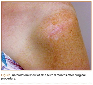
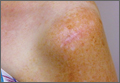
Cutaneous Burn Caused by Radiofrequency Ablation Probe During Shoulder Arthroscopy
Cautery and radiofrequency ablation (RFA) devices are commonly used in shoulder arthroscopic surgery for hemostasis and ablation of soft tissue. Although these devices are easily used and applied, complications (eg, extensive release of deltoid muscle,1 nerve damage,2 tendon damage,3 cartilage damage from heat transfer4) can occur during arthroscopic surgery. Radiofrequency devices can elevate fluid temperatures to unsafe levels and directly or indirectly injure surrounding tissue.5,6 Skin complications from using these devices include direct burns to the subcutaneous tissues from the joint to the skin surface7 and skin burns related to overheated arthroscopic fluid.8
In our English-language literature review, however, we found no report of a skin burn secondary to contact between a RFA device and a spinal needle used in identifying structures during an arthroscopic acromioplasty. We report such a case here. The patient provided written informed consent for print and electronic publication of this case report.
Case Report
A 51-year-old woman injured her left, nondominant shoulder when a descending garage door hit her directly on the superior aspect of the shoulder. She had immediate onset of pain on the top and lateral side of the shoulder and was evaluated by a primary care physician. Radiographs and magnetic resonance imaging (MRI) were normal. The patient was referred to an orthopedic surgeon for further evaluation.
The orthopedic surgeon found her to be in good health, with no history of diabetes, vascular conditions, or skin disorders. The initial diagnosis after history taking and physical examination was impingement syndrome with subacromial bursitis. The surgeon recommended nonoperative treatment: ice, nonsteroidal anti-inflammatory drugs, and physical therapy. After 3 months, the patient’s examination was unchanged, and there was no improvement in pain. Cortisone injected into the subacromial space helped for a few weeks, but the pain returned. After 2 more cortisone injections over 9 months failed, repeat MRI showed no tears of the rotator cuff or any other salient abnormalities. The treatment options were discussed with the patient, and, because the physical examination findings were consistent with impingement syndrome and nonoperative measures had failed, she consented to arthroscopic evaluation of the shoulder and arthroscopic partial anterior-lateral acromioplasty.
The procedure was performed 8 months after initial injury. With the patient under general anesthesia and in a lateral decubitus position, her arm was placed in an arm holder. Before the partial acromioplasty, two 18-gauge spinal needles were inserted from the skin surface into the subacromial space to help localize the anterolateral acromion and the acromioclavicular joint. The procedure was performed with a pump using saline bags kept at room temperature. A bipolar radiofrequency device (Stryker Energy Radiofrequency Ablation System; Stryker, Mahwah, New Jersey) was used to débride the subacromial bursa and the periosteum of the undersurface of the acromion. While the bursa was being débrided, the radiofrequency device inadvertently touched the anterior lateral needle probe, and a small skin burn formed around the needle on the surface of the shoulder (Figure). The radiofrequency device did not directly contact the skin, and the deltoid fascia was intact. The spinal needle was removed, and the skin around the burn was excised; the muscle beneath the skin was intact and showed no signs of thermal damage. The skin was mobilized and closed with interrupted simple sutures using a 4-0 nylon suture. The procedure was then completed with no other complications.
After surgery, the patient recovered without complications, and the skin lesion healed with no signs of infection and no skin or muscle defects. Some stiffness was treated with medication and physical therapy. Nine months after surgery, the patient reported mild shoulder stiffness and remained dissatisfied with the appearance of the skin in the area of the burn.
Discussion
Our patient’s case is a reminder that contact between a radiofrequency device and metal needles can transfer heat to tissues and cause skin burns. When using a radiofrequency device around metal needles or cannulas, surgeons should be sure to avoid prolonged contact with the metal. Our patient’s case is the first reported case of a thermal skin injury occurring when a spinal needle was heated by an arthroscopic ablater.
Other authors have reported indirect thermal skin injuries caused by radiofrequency devices during arthroscopic surgery, but the causes were postulated to be direct contact between device and skin7 and overheating of the arthroscopy fluid.5,6,8 Huang and colleagues8 reported that full-thickness skin burns occurred when normal saline used during routine knee arthroscopy overheated from use of a radiofrequency device. Burn lesions, noted on their patient’s leg within 1 day after surgery, required subsequent débridement, a muscle flap, and split-skin grafting. Skin burns caused by overheated fluid have occurred irrespective of type of fluid used (eg, 1.5% glycine or lactated Ringer solution).6 There was no evidence that our patient’s burn resulted from extravasated overheated fluid, as the lesion was localized to the area immediately around the needle and was not geographic, as was described by Huang and colleagues.8
Other possible causes of skin burns during arthroscopic surgery have been described, but none applies in our patient’s case. Segami and colleagues7 described a burn resulting from direct transfer of heat from the radiofrequency device to the skin because of their proximity. This mechanism was not the cause in our patient’s case; there was no evidence of a defect or burned deltoid muscle at time of surgery. Lau and Dao9 reported 2 small full-thickness skin burns caused by a fiberoptic-light cable tip placed on a patient’s leg; in addition, the hot (>170°C) cables caused the paper drapes to combust.9 Skin burns secondary to use of skin antiseptics have been reported,10 but such lesions typically are located beneath tourniquets or in areas of friction from surgical drapes. In some cases, lesions described as skin burns may actually have been pressure lesions secondary to moist skin and friction.11
Whether type of radiofrequency device contributes to the occurrence of heat-related lesions during arthroscopic surgery is unknown. Some investigators have suggested there is more potential for harm with bipolar RFA devices than with monopolar devices.12,13 Monopolar devices pass energy between a probe and a grounding plate, whereas bipolar devices pass energy through 2 points on the probe.14 Because the heat for the monopolar probe derives from the frictional resistance of tissues to each other rather than from the probe itself, the bipolar probe theoretically allows for better temperature control. In addition, bipolar probes require less current to achieve the same heating effect. However, recent studies have suggested that, compared with monopolar radiofrequency devices, bipolar radiofrequency devices are associated with larger increases in temperature at equal depths after an equal number of applications.12,13
To our knowledge, no one has specifically investigated the type of bipolar device used in the present case. This case report, the first to describe a thermal skin injury caused by direct contact between a radiofrequency device and a metal needle inserted in the skin, is a reminder that contact between radiofrequency devices and spinal needles or other metal cannulas used in arthroscopic surgery should be avoided.
1. Bonsell S. Detached deltoid during arthroscopic subacromial decompression. Arthroscopy. 2000;16(7):745-748.
2. Mohammed KD, Hayes MG, Saies AD. Unusual complications of shoulder arthroscopy. J Shoulder Elbow Surg. 2000;9(4):350-353.
3. Pell RF 4th, Uhl RL. Complications of thermal ablation in wrist arthroscopy. Arthroscopy. 2004;20(suppl 2):84-86.
4. Lu Y, Hayashi K, Hecht P, et al. The effect of monopolar radiofrequency energy on partial-thickness defects of articular cartilage. Arthroscopy. 2000;16(5):527-536.
5. Kouk SN, Zoric B, Stetson WB. Complication of the use of a radiofrequency device in arthroscopic shoulder surgery: second-degree burn of the shoulder girdle. Arthroscopy. 2011;27(1):136-141.
6. Lord MJ, Maltry JA, Shall LM. Thermal injury resulting from arthroscopic lateral retinacular release by electrocautery: report of three cases and a review of the literature. Arthroscopy. 1991;7(1):33-37.
7. Segami N, Yamada T, Nishimura M. Thermal injury during temporomandibular joint arthroscopy: a case report. J Oral Maxillofac Surg. 2004;62(4):508-510.
8. Huang S, Gateley D, Moss ALH. Accidental burn injury during knee arthroscopy. Arthroscopy. 2007;23(12):1363.e1-e3.
9. Lau YJ, Dao Q. Cutaneous burns from a fiberoptic cable tip during arthroscopy of the knee. Knee. 2008;15(4):333-335.
10. Sanders TH, Hawken SM. Chlorhexidine burns after shoulder arthroscopy. Am J Orthop. 2012;41(4):172-174.
11. Keyurapan E, Hu SJ, Redett R, McCarthy EF, McFarland EG. Pressure ulcers of the thorax after shoulder surgery. Knee Surg Sports Traumatol Arthrosc. 2007;15(12):1489-1493.
12. Edwards RB 3rd, Lu Y, Rodriguez E, Markel MD. Thermometric determination of cartilage matrix temperatures during thermal chondroplasty: comparison of bipolar and monopolar radiofrequency devices. Arthroscopy. 2002;18(4):339-346.
13. Figueroa D, Calvo R, Vaisman A, et al. Bipolar radiofrequency in the human meniscus. Comparative study between patients younger and older than 40 years of age. Knee. 2007;14(5):357-360.
14. Sahasrabudhe A, McMahon PJ. Thermal probes: what’s available in 2004. Oper Tech Sports Med. 2004;12:206-209.
Cautery and radiofrequency ablation (RFA) devices are commonly used in shoulder arthroscopic surgery for hemostasis and ablation of soft tissue. Although these devices are easily used and applied, complications (eg, extensive release of deltoid muscle,1 nerve damage,2 tendon damage,3 cartilage damage from heat transfer4) can occur during arthroscopic surgery. Radiofrequency devices can elevate fluid temperatures to unsafe levels and directly or indirectly injure surrounding tissue.5,6 Skin complications from using these devices include direct burns to the subcutaneous tissues from the joint to the skin surface7 and skin burns related to overheated arthroscopic fluid.8
In our English-language literature review, however, we found no report of a skin burn secondary to contact between a RFA device and a spinal needle used in identifying structures during an arthroscopic acromioplasty. We report such a case here. The patient provided written informed consent for print and electronic publication of this case report.
Case Report
A 51-year-old woman injured her left, nondominant shoulder when a descending garage door hit her directly on the superior aspect of the shoulder. She had immediate onset of pain on the top and lateral side of the shoulder and was evaluated by a primary care physician. Radiographs and magnetic resonance imaging (MRI) were normal. The patient was referred to an orthopedic surgeon for further evaluation.
The orthopedic surgeon found her to be in good health, with no history of diabetes, vascular conditions, or skin disorders. The initial diagnosis after history taking and physical examination was impingement syndrome with subacromial bursitis. The surgeon recommended nonoperative treatment: ice, nonsteroidal anti-inflammatory drugs, and physical therapy. After 3 months, the patient’s examination was unchanged, and there was no improvement in pain. Cortisone injected into the subacromial space helped for a few weeks, but the pain returned. After 2 more cortisone injections over 9 months failed, repeat MRI showed no tears of the rotator cuff or any other salient abnormalities. The treatment options were discussed with the patient, and, because the physical examination findings were consistent with impingement syndrome and nonoperative measures had failed, she consented to arthroscopic evaluation of the shoulder and arthroscopic partial anterior-lateral acromioplasty.
The procedure was performed 8 months after initial injury. With the patient under general anesthesia and in a lateral decubitus position, her arm was placed in an arm holder. Before the partial acromioplasty, two 18-gauge spinal needles were inserted from the skin surface into the subacromial space to help localize the anterolateral acromion and the acromioclavicular joint. The procedure was performed with a pump using saline bags kept at room temperature. A bipolar radiofrequency device (Stryker Energy Radiofrequency Ablation System; Stryker, Mahwah, New Jersey) was used to débride the subacromial bursa and the periosteum of the undersurface of the acromion. While the bursa was being débrided, the radiofrequency device inadvertently touched the anterior lateral needle probe, and a small skin burn formed around the needle on the surface of the shoulder (Figure). The radiofrequency device did not directly contact the skin, and the deltoid fascia was intact. The spinal needle was removed, and the skin around the burn was excised; the muscle beneath the skin was intact and showed no signs of thermal damage. The skin was mobilized and closed with interrupted simple sutures using a 4-0 nylon suture. The procedure was then completed with no other complications.
After surgery, the patient recovered without complications, and the skin lesion healed with no signs of infection and no skin or muscle defects. Some stiffness was treated with medication and physical therapy. Nine months after surgery, the patient reported mild shoulder stiffness and remained dissatisfied with the appearance of the skin in the area of the burn.
Discussion
Our patient’s case is a reminder that contact between a radiofrequency device and metal needles can transfer heat to tissues and cause skin burns. When using a radiofrequency device around metal needles or cannulas, surgeons should be sure to avoid prolonged contact with the metal. Our patient’s case is the first reported case of a thermal skin injury occurring when a spinal needle was heated by an arthroscopic ablater.
Other authors have reported indirect thermal skin injuries caused by radiofrequency devices during arthroscopic surgery, but the causes were postulated to be direct contact between device and skin7 and overheating of the arthroscopy fluid.5,6,8 Huang and colleagues8 reported that full-thickness skin burns occurred when normal saline used during routine knee arthroscopy overheated from use of a radiofrequency device. Burn lesions, noted on their patient’s leg within 1 day after surgery, required subsequent débridement, a muscle flap, and split-skin grafting. Skin burns caused by overheated fluid have occurred irrespective of type of fluid used (eg, 1.5% glycine or lactated Ringer solution).6 There was no evidence that our patient’s burn resulted from extravasated overheated fluid, as the lesion was localized to the area immediately around the needle and was not geographic, as was described by Huang and colleagues.8
Other possible causes of skin burns during arthroscopic surgery have been described, but none applies in our patient’s case. Segami and colleagues7 described a burn resulting from direct transfer of heat from the radiofrequency device to the skin because of their proximity. This mechanism was not the cause in our patient’s case; there was no evidence of a defect or burned deltoid muscle at time of surgery. Lau and Dao9 reported 2 small full-thickness skin burns caused by a fiberoptic-light cable tip placed on a patient’s leg; in addition, the hot (>170°C) cables caused the paper drapes to combust.9 Skin burns secondary to use of skin antiseptics have been reported,10 but such lesions typically are located beneath tourniquets or in areas of friction from surgical drapes. In some cases, lesions described as skin burns may actually have been pressure lesions secondary to moist skin and friction.11
Whether type of radiofrequency device contributes to the occurrence of heat-related lesions during arthroscopic surgery is unknown. Some investigators have suggested there is more potential for harm with bipolar RFA devices than with monopolar devices.12,13 Monopolar devices pass energy between a probe and a grounding plate, whereas bipolar devices pass energy through 2 points on the probe.14 Because the heat for the monopolar probe derives from the frictional resistance of tissues to each other rather than from the probe itself, the bipolar probe theoretically allows for better temperature control. In addition, bipolar probes require less current to achieve the same heating effect. However, recent studies have suggested that, compared with monopolar radiofrequency devices, bipolar radiofrequency devices are associated with larger increases in temperature at equal depths after an equal number of applications.12,13
To our knowledge, no one has specifically investigated the type of bipolar device used in the present case. This case report, the first to describe a thermal skin injury caused by direct contact between a radiofrequency device and a metal needle inserted in the skin, is a reminder that contact between radiofrequency devices and spinal needles or other metal cannulas used in arthroscopic surgery should be avoided.
1. Bonsell S. Detached deltoid during arthroscopic subacromial decompression. Arthroscopy. 2000;16(7):745-748.
2. Mohammed KD, Hayes MG, Saies AD. Unusual complications of shoulder arthroscopy. J Shoulder Elbow Surg. 2000;9(4):350-353.
3. Pell RF 4th, Uhl RL. Complications of thermal ablation in wrist arthroscopy. Arthroscopy. 2004;20(suppl 2):84-86.
4. Lu Y, Hayashi K, Hecht P, et al. The effect of monopolar radiofrequency energy on partial-thickness defects of articular cartilage. Arthroscopy. 2000;16(5):527-536.
5. Kouk SN, Zoric B, Stetson WB. Complication of the use of a radiofrequency device in arthroscopic shoulder surgery: second-degree burn of the shoulder girdle. Arthroscopy. 2011;27(1):136-141.
6. Lord MJ, Maltry JA, Shall LM. Thermal injury resulting from arthroscopic lateral retinacular release by electrocautery: report of three cases and a review of the literature. Arthroscopy. 1991;7(1):33-37.
7. Segami N, Yamada T, Nishimura M. Thermal injury during temporomandibular joint arthroscopy: a case report. J Oral Maxillofac Surg. 2004;62(4):508-510.
8. Huang S, Gateley D, Moss ALH. Accidental burn injury during knee arthroscopy. Arthroscopy. 2007;23(12):1363.e1-e3.
9. Lau YJ, Dao Q. Cutaneous burns from a fiberoptic cable tip during arthroscopy of the knee. Knee. 2008;15(4):333-335.
10. Sanders TH, Hawken SM. Chlorhexidine burns after shoulder arthroscopy. Am J Orthop. 2012;41(4):172-174.
11. Keyurapan E, Hu SJ, Redett R, McCarthy EF, McFarland EG. Pressure ulcers of the thorax after shoulder surgery. Knee Surg Sports Traumatol Arthrosc. 2007;15(12):1489-1493.
12. Edwards RB 3rd, Lu Y, Rodriguez E, Markel MD. Thermometric determination of cartilage matrix temperatures during thermal chondroplasty: comparison of bipolar and monopolar radiofrequency devices. Arthroscopy. 2002;18(4):339-346.
13. Figueroa D, Calvo R, Vaisman A, et al. Bipolar radiofrequency in the human meniscus. Comparative study between patients younger and older than 40 years of age. Knee. 2007;14(5):357-360.
14. Sahasrabudhe A, McMahon PJ. Thermal probes: what’s available in 2004. Oper Tech Sports Med. 2004;12:206-209.
Office-Based Rapid Prototyping in Orthopedic Surgery: A Novel Planning Technique and Review of the Literature
Three-dimensional (3-D) printing is a rapidly evolving technology with both medical and nonmedical applications.1,2 Rapid prototyping involves creating a physical model of human tissue from a 3-D computer-generated rendering.3 The method relies on export of Digital Imaging and Communications in Medicine (DICOM)–based computed tomography (CT) or magnetic resonance imaging (MRI) data into standard triangular language (STL) format. Reducing CT or MRI slice thickness increases resolution of the final model.2 Five types of rapid prototyping exist: STL, selective laser sintering, fused deposition modeling, multijet modeling, and 3-D printing.
Most implant manufacturers can produce a 3-D model based on surgeon-provided DICOM images. The ability to produce anatomical models in an office-based setting is a more recent development. Three-dimensional modeling may allow for more accurate and extensive preoperative planning than radiographic examination alone does, and may even allow surgeons to perform procedures as part of preoperative preparation. This can allow for early recognition of unanticipated intraoperative problems or of the need for special techniques and implants that would not have been otherwise available, all of which may ultimately reduce operative time.
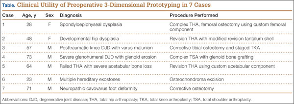
The breadth of applications for office-based 3-D prototyping is not well described in the orthopedic surgery literature. In this article, we describe 7 cases of complex orthopedic disorders that were surgically treated after preoperative planning in which use of a 3-D printer allowed for “mock” surgery before the actual procedures. In 3 of the cases, the models were made by the implant manufacturers. Working with these models prompted us to buy a 3-D printer (Fortus 250; Stratasys, Eden Prairie, Minnesota) for in-office use. In the other 4 cases, we used this printer to create our own models. As indicated in the manufacturer’s literature, the printer uses fused deposition modeling, which builds a model layer by layer by heating thermoplastic material to a semi-liquid state and extruding it according to computer-controlled pathways.
We present preoperative images, preoperative 3-D modeling, and intraoperative and postoperative images along with brief case descriptions (Table). The patients provided written informed consent for print and electronic publication of these case reports.
Case Reports
Case 1
A 28-year-old woman with a history of spondyloepiphyseal dysplasia presented to our clinic with bilateral hip pain. About 8 years earlier, she had undergone bilateral proximal and distal femoral osteotomies. Her function had initially improved, but over the 2 to 3 years before presentation she began having more pain and stiffness with activity. At time of initial evaluation, she was able to walk only 1 to 2 blocks and had difficulty getting in and out of a car and up out of a seated position.
On physical examination, the patient was 3 feet 10 inches tall and weighed 77 pounds. She ambulated with decreased stance phase on both lower extremities and had developed a significant amount of increased forward pelvic inclination and increased lumbar lordosis. Both hips and thighs had multiple healed scars from prior surgeries and pin tracts. Range of motion (ROM) on both sides was restricted to 85° of flexion, 10° of internal rotation, 15° of external rotation, and 15° of abduction.
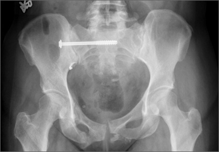
Plain radiographs showed advanced degenerative joint disease (DJD) of both hips with dysplastic acetabuli and evidence of healed osteotomies (Figure 1). Femoral deformities, noted bilaterally, consisted of marked valgus proximally and varus distally. Preoperative CT was used to create a 3-D model of the pelvis and femur. The model was created by the same implant manufacturer that produced the final components (Depuy, Warsaw, Indiana). Corrective femoral osteotomy was performed on the model to allow for design and use of a custom implant, while the modeled pelvis confirmed the ability to reproduce the normal hip center with a 44-mm conventional hemispherical socket.
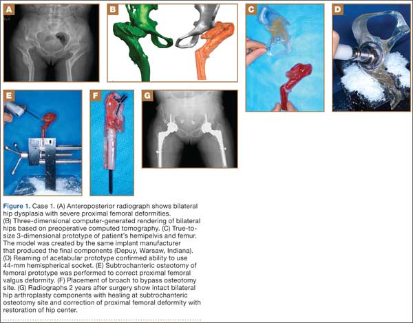
After surgery, the patient was able to ambulate without a limp and return to work. Her hip ROM was pain-free passively and actively with flexion to 100°, internal rotation to 35°, external rotation to 20°, and abduction to 30°.
Case 2
A 48-year-old woman with a history of Crowe IV hip dysplasia presented to our clinic with a chronically dislocated right total hip arthroplasty (THA) (Figure 2). Her initial THA was revised 1 year later because of acetabular component failure. Two years later, she was diagnosed with a deep periprosthetic infection, which was ultimately treated with 2-stage reimplantation. She subsequently dislocated and underwent re-revision of the S-ROM body and stem (DePuy Synthes, Warsaw, Indiana). At a visit after that revision, she was noted to be chronically dislocated, and was sent to our clinic for further management.
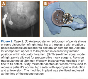
Preoperative radiographs showed a right uncemented THA with the femoral head dislocated toward the false acetabulum, retained hardware, and an old ununited trochanteric fragment. Both the femoral and acetabular components appeared well-fixed, though the acetabular component was positioned inferior, toward the obturator foramen.
Preoperative CT with metal artifact subtraction was used to create a 3-D model of the residual bony pelvis. The model was made by an implant manufacturer (Zimmer, Warsaw, Indiana). The shape of the superior defect was amenable to reconstruction using a modified revision trabecular metal socket. The pelvic model was reamed to accept a conventional hemispherical socket. The defect was reamed to accept a modified revision trabecular metal socket. The real implant was fashioned before surgery and was sterilized to avoid the need for intraoperative modification. Use of the preoperative model significantly reduced the time that would have been needed to modify the implant during actual surgery.
The patient’s right THA was revised. At time of surgery, the modified revision trabecular metal acetabular component was noted to seat appropriately in the superior defect. The true acetabulum was reestablished, and a hemispherical socket was placed with multiple screws. The 2 components were then unitized using cement in the same manner as would be done with an off-the-shelf augment.
Case 3
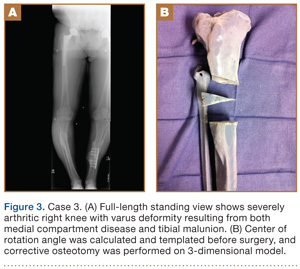
A 57-year-old man presented with a 10-year history of right knee pain. About 30 years before presentation at our clinic, he was treated for an open right tibia fracture sustained in a motorcycle accident. He had been treated nonsurgically, with injections, but they failed to provide sustained relief.
Preoperative radiographs showed severe advanced DJD in conjunction with an extra-articular posttraumatic varus tibial shaft deformity (Figure 3). An implant manufacturer (Zimmer) used a CT scan to create a model of the deformity. The resultant center of rotation angle was calculated using preoperative images and conventional techniques for deformity correction, and a lateral closing-wedge osteotomy was performed on the CT-based model. The initial attempt at deformity correction was slightly excessive, and the amount of resected bone slightly thicker than the calculated wedge, resulting in a valgus deformity. This error was noted, and the decision was made to recut a new model with a slight amount of residual varus that could be corrected during the final knee arthroplasty procedure.
Corrective osteotomy was performed with a lateral plate. Six months later, the patient had no residual pain, and CT confirmed union at the osteotomy site and a slight amount of residual varus. The patient then underwent routine total knee arthroplasty (TKA) using an abbreviated keel to avoid the need for removal of the previously placed hardware. The varus deformity was completely corrected.
Case 4
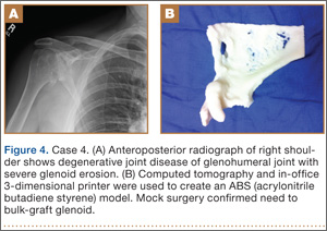
A 73-year-old man had a history of shoulder pain dating back to his childhood. Despite treatment with nonsteroidal anti-inflammatory drugs, physical therapy, and injections, his debilitating pain persisted. Physical examination revealed limited ROM and an intact rotator cuff.
Plain radiographs showed severe DJD of the glenohumeral joint (Figure 4). Severe erosions of the glenoid were noted, prompting further workup with CT, which showed significant bone loss, particularly along the posterior margin of the glenoid. We used our 3-D printer to create a model of the scapula from CT images. The model was then reamed in the usual fashion to accept a 3-pegged glenoid component. On placement of a trial implant, a large deficiency was seen posteriorly. We thought the size and location of the defect made it amenable to grafting using the patient’s humeral head.
The patient elected to undergo right total shoulder arthroplasty. During the procedure, the glenoid defect was found to be identical to what was encountered with the model before surgery. A portion of the patient’s humeral head was then fashioned to fit the defect, and was secured with three 2.7-mm screws, after provisional fixation using 2.0-mm Kirschner wires. The screws were countersunk, and the graft was contoured by hand to match the previous reaming. A 3-pegged 52-mm glenoid component was then cemented into position with excellent stability.
Case 5
A 64-year-old man presented to our clinic with left hip pain 40 years after THA. The original procedure was performed for resolved proximal femoral osteomyelitis. Plain radiographs showed a loose cemented McKee-Farrar hip arthroplasty (Figure 5). Because of the elevated position of the acetabular component relative to the native hip center, CT was used to determine the amount of femoral bone loss.
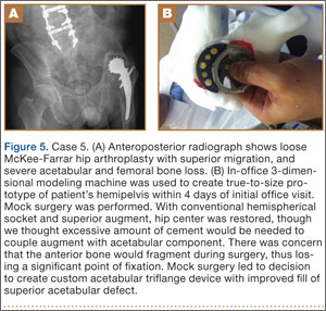
We used our 3-D printer to create a model and tried to recreate the native hip center with conventional off-the-shelf implants. A 50-mm hemispherical socket trial was placed in the appropriate location, along with a trabecular metal augment trial to provide extended coverage over the superolateral portion of the socket. Noted between the socket and the augment was a large gap; a substantial amount of cement would have been needed to unitize the construct. We thought a custom acetabular component would avoid the need for cement. In addition, given the patient’s small stature, the conventional acetabular component would allow a head only 32 mm in diameter. With a custom implant, the head could be enlarged to 36 mm, providing improved ROM and stability.
The patient underwent revision left hip arthroplasty using a custom acetabular component. A 3-D model available at time of surgery was used to aid implant placement.
Case 6
A 23-year-old man with multiple hereditary exostoses presented to our clinic with a painful mass in the left calf. Plain radiographs showed extensive osteochondromatosis involving the left proximal tibiofibular joint (Figure 6). The exostosis extended posteromedially, displacing the arterial trifurcation. MRI showed a small cartilage cap without evidence of malignant transformation.
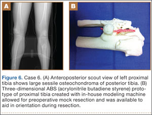
CT angiogram allowed the vasculature to be modeled along with the deformity. A 3-D model was fabricated. The model included the entire proximal tibiofibular joint, as well as the anterior tibial, peroneal, and posterior tibial arteries. Cautious intralesional resection was recommended because of the proximity to all 3 vessels.
The patient underwent tumor resection through a longitudinal posterior approach. The interval between the medial and lateral heads of the gastrocnemius muscles was developed to expose the underlying soleus muscle. The soleus was split longitudinally from its hiatus to the inferior portion of the exostosis. This allowed for identification of the trifurcation and the tibial nerve, which were protected. Osteotomes were used to resect the mass at its base, the edges were carefully trimmed, and bone wax was placed over the defect. Anterior and lateral to this mass was another large mass (under the soleus muscle), which was also transected using an osteotome. The gastrocnemius and soleus muscles were then reflected off the fibula in order to remove 2 other exostoses, beneath the neck and head of the fibula.
Case 7
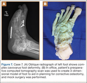
A 71-year-old man with a history of idiopathic lymphedema and peripheral neuropathy presented to our clinic with a left cavovarus foot deformity and a history of recurrent neuropathic foot ulcers (Figure 7). Physical examination revealed a callus over the lateral aspect of the base of the fifth metatarsal. Preoperative radiograph showed evidence of prior triple arthrodesis with a cavovarus foot deformity. CT scan was used to create a 3-D model of the foot. The model was then used to identify an appropriate location for lateral midtarsal and calcaneal closing-wedge osteotomies.
The patient underwent midfoot and hindfoot surgical correction. At surgery, the lateral closing-wedge osteotomies were performed according to the preoperative model. Radiographs 1 year after surgery showed correction of the forefoot varus.
Discussion
Three-dimensional printing for medical applications of anatomical modeling is not a new concept.1,3,4 Its use has been reported for a variety of applications in orthopedic surgery, including the printing of porous and metallic surfaces5 and bone-tissue engineering.6-9 Rapid prototyping for medical application was first reported in 1990 when a CT-based model was used to create a cranial bone.10 Reports of using the technique are becoming more widespread, particularly in the dental and maxillofacial literature, which includes reports on a variety of applications, including patient-specific drill guides, splints, and implants.11-14 The ability to perform mock surgery in advance of an actual procedure provides an invaluable opportunity to anticipate potential intraoperative problems, reduce operative time, and improve the accuracy of reconstruction.
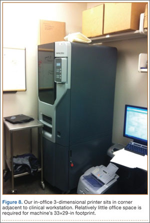
Office-based rapid prototyping that uses an in-house 3-D printer is a novel application of this technology. It allows for creation of a patient-specific model for preoperative planning purposes. We are unaware of any other reports demonstrating the breadth and utility of office-based rapid prototyping in orthopedic surgery. For general reference, a printer similar to ours requires an initial investment of $52,000 to $56,000. This cost generally covers the printer, printer base cabinet, installation, training, and printer software (different from the 3-D modeling software), plus a 1-year warranty. A service agreement costs about $4000 annually. Printer and model supply expenses depend on the material used for the model (eg, ABS [acrylonitrile butadiene styrene]) and on the size and complexity of the 3-D models created. Average time to generate an appropriately formatted 3-D printing file is about 1 hour, though times can vary largely, according to amount of metal artifact subtraction necessary and the experience of the software user. For the rare, extremely complex deformities that require a significant amount of metal artifact subtraction, file preparation times can exceed 3 or 4 hours. We think these preparation times will decrease as communication between radiology file export format and modeling software ultimately allows for metal artifact subtraction images to function within the modeling software environment. Once an appropriately formatted file has been created, typical printing times vary according to the size of the to-be-modeled bone. For a hemipelvis, printing time is 30 to 40 hours; printing that is started on a Friday afternoon will be complete by Monday morning.
There are few reports of rapid prototyping in orthopedic surgery. In 2003, Minns and colleagues15 used a 3-D model in the planning of a tibial resection for TKA. They found the model to be accurate at time of surgery, resulting in appropriate tibial coverage by a conventional meniscal-bearing implant. Munjal and colleagues16 reported on 10 complex failed hip arthroplasty cases in which patients had revision surgery after preoperative planning using 3-D modeling techniques. The authors found that, in 8 of the 10 cases, conventional classification systems of bone loss were inaccurate in comparison with the prototype. Four cases required reconstruction with a custom triflange when conventional implants were not deemed reasonable based on the pelvic model. Tam and colleagues17 reported using a 3-D prototype as an aid in surgical planning for resection of a scapular osteochondroma in a 6-year-old patient. They found the rapid prototype to be useful at time of resection—similar to what we found with 1 patient (case 6). Adding contrast media to our patient’s scan allowed for 3-D visualization of the lesion and the encased vasculature. Fu and colleagues18 reported using a patient-specific drill template to insert anterior transpedicular screws. They constructed 24 prototypes of a formalin-preserved cervical vertebra to create a patient-specific biocompatible drill template for use in correcting multilevel cervical instability. They found the technique to be highly reproducible and accurate. Zein and colleagues19 used a rapid prototype of 3 consecutive human livers to preoperatively identify the vascular and biliary tract anatomy. They reported a high degree of accuracy—mean dimensional errors of less than 4 mm for the entire model and 1.3 mm for the vascular diameter.
The models created by implant manufacturers in this series were used to perform “mock” surgery before the actual procedures. Working with these models prompted us to buy our own 3-D printer. The learning curve can be steep, but commercially available 3-D printers allow for prompt in-office production of high-quality realistic prototypes at relatively low per-case cost (Figure 8). Three-dimensional modeling allows surgeons to assess the accuracy of their original surgical plans and, if necessary, correct them before surgery. Although computer-aided design models are useful, the ability to “perform surgery preoperatively” adds another element to surgeons’ understanding of the potential issues that may arise. Also, an in-office printer can help improve surgeons’ understanding and control over the process by which images are translated from radiographic file to 3-D model. Disadvantages of an in-office system include start-up and maintenance costs, office space requirements, and a significant learning curve for software and hardware applications. In addition, creation of 3-D models requires close interaction with radiologists who can provide appropriately formatted DICOM images, as metal artifact subtraction can be challenging. We think that, as image formatting and software capabilities are continually refined, this technology will become an invaluable part of multiple subspecialties across orthopedic surgery, with potentially infinite clinical, educational, and research applications.
1. McGurk M, Amis AA, Potamianos P, Goodger NM. Rapid prototyping techniques for anatomical modelling in medicine. Ann R Coll Surg Engl. 1997;79(3):169-174.
2. Webb PA. A review of rapid prototyping (RP) techniques in the medical and biomedical sector. J Med Eng Technol. 2000;24(4):149-153.
3. Esses SJ, Berman P, Bloom AI, Sosna J. Clinical applications of physical 3D models derived from MDCT data and created by rapid prototyping. AJR Am J Roentgenol. 2011;196(6):W683-W688.
4. Torres K, Staśkiewicz G, Śnieżyński M, Drop A, Maciejewski R. Application of rapid prototyping techniques for modelling of anatomical structures in medical training and education. Folia Morphol. 2011;70(1):1-4.
5. Melican MC, Zimmerman MC, Dhillon MS, Ponnambalam AR, Curodeau A, Parsons JR. Three-dimensional printing and porous metallic surfaces: a new orthopedic application. J Biomed Mater Res. 2001;55(2):194-202.
6. Butscher A, Bohner M, Hofmann S, Gauckler L, Müller R. Structural and material approaches to bone tissue engineering in powder-based three-dimensional printing. Acta Biomater. 2011;7(3):907-920.
7. Ciocca L, De Crescenzio F, Fantini M, Scotti R. CAD/CAM and rapid prototyped scaffold construction for bone regenerative medicine and surgical transfer of virtual planning: a pilot study. Comput Med Imaging Graph. 2009;33(1):58-62.
8. Leukers B, Gülkan H, Irsen SH, et al. Hydroxyapatite scaffolds for bone tissue engineering made by 3D printing. J Mater Sci Mater Med. 2005;16(12):1121-1124.
9. Seitz H, Rieder W, Irsen S, Leukers B, Tille C. Three-dimensional printing of porous ceramic scaffolds for bone tissue engineering. J Biomed Mater Res B Appl Biomater. 2005;74(2):782-788.
10. Mankovich NJ, Cheeseman AM, Stoker NG. The display of three-dimensional anatomy with stereolithographic models. J Digit Imaging. 1990;3(3):200-203.
11. Flügge TV, Nelson K, Schmelzeisen R, Metzger MC. Three-dimensional plotting and printing of an implant drilling guide: simplifying guided implant surgery. J Oral Maxillofac Surg. 2013;71(8):1340-1346.
12. Goiato MC, Santos MR, Pesqueira AA, Moreno A, dos Santos DM, Haddad MF. Prototyping for surgical and prosthetic treatment. J Craniofac Surg. 2011;22(3):914-917.
13. Metzger MC, Hohlweg-Majert B, Schwarz U, Teschner M, Hammer B, Schmelzeisen R. Manufacturing splints for orthognathic surgery using a three-dimensional printer. Oral Surg Oral Med Oral Pathol Oral Radiol Endod. 2008;105(2):e1-e7.
14. Robiony M, Salvo I, Costa F, et al. Virtual reality surgical planning for maxillofacial distraction osteogenesis: the role of reverse engineering rapid prototyping and cooperative work. J Oral Maxillofac Surg. 2007;65(6):1198-1208.
15. Minns RJ, Bibb R, Banks R, Sutton RA. The use of a reconstructed three-dimensional solid model from CT to aid the surgical management of a total knee arthroplasty: a case study. Med Eng Phys. 2003;25(6):523-526.
16. Munjal S, Leopold SS, Kornreich D, Shott S, Finn HA. CT-generated 3-dimensional models for complex acetabular reconstruction. J Arthroplasty. 2000;15(5):644-653.
17. Tam MD, Laycock SD, Bell D, Chojnowski A. 3-D printout of a DICOM file to aid surgical planning in a 6 year old patient with a large scapular osteochondroma complicating congenital diaphyseal aclasia. J Radiol Case Rep. 2012;6(1):31-37.
18. Fu M, Lin L, Kong X, et al. Construction and accuracy assessment of patient-specific biocompatible drill template for cervical anterior transpedicular screw (ATPS) insertion: an in vitro study. PLoS One. 2013;8(1):e53580.
19. Zein NN, Hanouneh IA, Bishop PD, et al. Three-dimensional print of a liver for preoperative planning in living donor liver transplantation. Liver Transpl. 2013;19(12):1304-1310.
Three-dimensional (3-D) printing is a rapidly evolving technology with both medical and nonmedical applications.1,2 Rapid prototyping involves creating a physical model of human tissue from a 3-D computer-generated rendering.3 The method relies on export of Digital Imaging and Communications in Medicine (DICOM)–based computed tomography (CT) or magnetic resonance imaging (MRI) data into standard triangular language (STL) format. Reducing CT or MRI slice thickness increases resolution of the final model.2 Five types of rapid prototyping exist: STL, selective laser sintering, fused deposition modeling, multijet modeling, and 3-D printing.
Most implant manufacturers can produce a 3-D model based on surgeon-provided DICOM images. The ability to produce anatomical models in an office-based setting is a more recent development. Three-dimensional modeling may allow for more accurate and extensive preoperative planning than radiographic examination alone does, and may even allow surgeons to perform procedures as part of preoperative preparation. This can allow for early recognition of unanticipated intraoperative problems or of the need for special techniques and implants that would not have been otherwise available, all of which may ultimately reduce operative time.
The breadth of applications for office-based 3-D prototyping is not well described in the orthopedic surgery literature. In this article, we describe 7 cases of complex orthopedic disorders that were surgically treated after preoperative planning in which use of a 3-D printer allowed for “mock” surgery before the actual procedures. In 3 of the cases, the models were made by the implant manufacturers. Working with these models prompted us to buy a 3-D printer (Fortus 250; Stratasys, Eden Prairie, Minnesota) for in-office use. In the other 4 cases, we used this printer to create our own models. As indicated in the manufacturer’s literature, the printer uses fused deposition modeling, which builds a model layer by layer by heating thermoplastic material to a semi-liquid state and extruding it according to computer-controlled pathways.
We present preoperative images, preoperative 3-D modeling, and intraoperative and postoperative images along with brief case descriptions (Table). The patients provided written informed consent for print and electronic publication of these case reports.
Case Reports
Case 1
A 28-year-old woman with a history of spondyloepiphyseal dysplasia presented to our clinic with bilateral hip pain. About 8 years earlier, she had undergone bilateral proximal and distal femoral osteotomies. Her function had initially improved, but over the 2 to 3 years before presentation she began having more pain and stiffness with activity. At time of initial evaluation, she was able to walk only 1 to 2 blocks and had difficulty getting in and out of a car and up out of a seated position.
On physical examination, the patient was 3 feet 10 inches tall and weighed 77 pounds. She ambulated with decreased stance phase on both lower extremities and had developed a significant amount of increased forward pelvic inclination and increased lumbar lordosis. Both hips and thighs had multiple healed scars from prior surgeries and pin tracts. Range of motion (ROM) on both sides was restricted to 85° of flexion, 10° of internal rotation, 15° of external rotation, and 15° of abduction.
Plain radiographs showed advanced degenerative joint disease (DJD) of both hips with dysplastic acetabuli and evidence of healed osteotomies (Figure 1). Femoral deformities, noted bilaterally, consisted of marked valgus proximally and varus distally. Preoperative CT was used to create a 3-D model of the pelvis and femur. The model was created by the same implant manufacturer that produced the final components (Depuy, Warsaw, Indiana). Corrective femoral osteotomy was performed on the model to allow for design and use of a custom implant, while the modeled pelvis confirmed the ability to reproduce the normal hip center with a 44-mm conventional hemispherical socket.
After surgery, the patient was able to ambulate without a limp and return to work. Her hip ROM was pain-free passively and actively with flexion to 100°, internal rotation to 35°, external rotation to 20°, and abduction to 30°.
Case 2
A 48-year-old woman with a history of Crowe IV hip dysplasia presented to our clinic with a chronically dislocated right total hip arthroplasty (THA) (Figure 2). Her initial THA was revised 1 year later because of acetabular component failure. Two years later, she was diagnosed with a deep periprosthetic infection, which was ultimately treated with 2-stage reimplantation. She subsequently dislocated and underwent re-revision of the S-ROM body and stem (DePuy Synthes, Warsaw, Indiana). At a visit after that revision, she was noted to be chronically dislocated, and was sent to our clinic for further management.
Preoperative radiographs showed a right uncemented THA with the femoral head dislocated toward the false acetabulum, retained hardware, and an old ununited trochanteric fragment. Both the femoral and acetabular components appeared well-fixed, though the acetabular component was positioned inferior, toward the obturator foramen.
Preoperative CT with metal artifact subtraction was used to create a 3-D model of the residual bony pelvis. The model was made by an implant manufacturer (Zimmer, Warsaw, Indiana). The shape of the superior defect was amenable to reconstruction using a modified revision trabecular metal socket. The pelvic model was reamed to accept a conventional hemispherical socket. The defect was reamed to accept a modified revision trabecular metal socket. The real implant was fashioned before surgery and was sterilized to avoid the need for intraoperative modification. Use of the preoperative model significantly reduced the time that would have been needed to modify the implant during actual surgery.
The patient’s right THA was revised. At time of surgery, the modified revision trabecular metal acetabular component was noted to seat appropriately in the superior defect. The true acetabulum was reestablished, and a hemispherical socket was placed with multiple screws. The 2 components were then unitized using cement in the same manner as would be done with an off-the-shelf augment.
Case 3
A 57-year-old man presented with a 10-year history of right knee pain. About 30 years before presentation at our clinic, he was treated for an open right tibia fracture sustained in a motorcycle accident. He had been treated nonsurgically, with injections, but they failed to provide sustained relief.
Preoperative radiographs showed severe advanced DJD in conjunction with an extra-articular posttraumatic varus tibial shaft deformity (Figure 3). An implant manufacturer (Zimmer) used a CT scan to create a model of the deformity. The resultant center of rotation angle was calculated using preoperative images and conventional techniques for deformity correction, and a lateral closing-wedge osteotomy was performed on the CT-based model. The initial attempt at deformity correction was slightly excessive, and the amount of resected bone slightly thicker than the calculated wedge, resulting in a valgus deformity. This error was noted, and the decision was made to recut a new model with a slight amount of residual varus that could be corrected during the final knee arthroplasty procedure.
Corrective osteotomy was performed with a lateral plate. Six months later, the patient had no residual pain, and CT confirmed union at the osteotomy site and a slight amount of residual varus. The patient then underwent routine total knee arthroplasty (TKA) using an abbreviated keel to avoid the need for removal of the previously placed hardware. The varus deformity was completely corrected.
Case 4
A 73-year-old man had a history of shoulder pain dating back to his childhood. Despite treatment with nonsteroidal anti-inflammatory drugs, physical therapy, and injections, his debilitating pain persisted. Physical examination revealed limited ROM and an intact rotator cuff.
Plain radiographs showed severe DJD of the glenohumeral joint (Figure 4). Severe erosions of the glenoid were noted, prompting further workup with CT, which showed significant bone loss, particularly along the posterior margin of the glenoid. We used our 3-D printer to create a model of the scapula from CT images. The model was then reamed in the usual fashion to accept a 3-pegged glenoid component. On placement of a trial implant, a large deficiency was seen posteriorly. We thought the size and location of the defect made it amenable to grafting using the patient’s humeral head.
The patient elected to undergo right total shoulder arthroplasty. During the procedure, the glenoid defect was found to be identical to what was encountered with the model before surgery. A portion of the patient’s humeral head was then fashioned to fit the defect, and was secured with three 2.7-mm screws, after provisional fixation using 2.0-mm Kirschner wires. The screws were countersunk, and the graft was contoured by hand to match the previous reaming. A 3-pegged 52-mm glenoid component was then cemented into position with excellent stability.
Case 5
A 64-year-old man presented to our clinic with left hip pain 40 years after THA. The original procedure was performed for resolved proximal femoral osteomyelitis. Plain radiographs showed a loose cemented McKee-Farrar hip arthroplasty (Figure 5). Because of the elevated position of the acetabular component relative to the native hip center, CT was used to determine the amount of femoral bone loss.
We used our 3-D printer to create a model and tried to recreate the native hip center with conventional off-the-shelf implants. A 50-mm hemispherical socket trial was placed in the appropriate location, along with a trabecular metal augment trial to provide extended coverage over the superolateral portion of the socket. Noted between the socket and the augment was a large gap; a substantial amount of cement would have been needed to unitize the construct. We thought a custom acetabular component would avoid the need for cement. In addition, given the patient’s small stature, the conventional acetabular component would allow a head only 32 mm in diameter. With a custom implant, the head could be enlarged to 36 mm, providing improved ROM and stability.
The patient underwent revision left hip arthroplasty using a custom acetabular component. A 3-D model available at time of surgery was used to aid implant placement.
Case 6
A 23-year-old man with multiple hereditary exostoses presented to our clinic with a painful mass in the left calf. Plain radiographs showed extensive osteochondromatosis involving the left proximal tibiofibular joint (Figure 6). The exostosis extended posteromedially, displacing the arterial trifurcation. MRI showed a small cartilage cap without evidence of malignant transformation.
CT angiogram allowed the vasculature to be modeled along with the deformity. A 3-D model was fabricated. The model included the entire proximal tibiofibular joint, as well as the anterior tibial, peroneal, and posterior tibial arteries. Cautious intralesional resection was recommended because of the proximity to all 3 vessels.
The patient underwent tumor resection through a longitudinal posterior approach. The interval between the medial and lateral heads of the gastrocnemius muscles was developed to expose the underlying soleus muscle. The soleus was split longitudinally from its hiatus to the inferior portion of the exostosis. This allowed for identification of the trifurcation and the tibial nerve, which were protected. Osteotomes were used to resect the mass at its base, the edges were carefully trimmed, and bone wax was placed over the defect. Anterior and lateral to this mass was another large mass (under the soleus muscle), which was also transected using an osteotome. The gastrocnemius and soleus muscles were then reflected off the fibula in order to remove 2 other exostoses, beneath the neck and head of the fibula.
Case 7
A 71-year-old man with a history of idiopathic lymphedema and peripheral neuropathy presented to our clinic with a left cavovarus foot deformity and a history of recurrent neuropathic foot ulcers (Figure 7). Physical examination revealed a callus over the lateral aspect of the base of the fifth metatarsal. Preoperative radiograph showed evidence of prior triple arthrodesis with a cavovarus foot deformity. CT scan was used to create a 3-D model of the foot. The model was then used to identify an appropriate location for lateral midtarsal and calcaneal closing-wedge osteotomies.
The patient underwent midfoot and hindfoot surgical correction. At surgery, the lateral closing-wedge osteotomies were performed according to the preoperative model. Radiographs 1 year after surgery showed correction of the forefoot varus.
Discussion
Three-dimensional printing for medical applications of anatomical modeling is not a new concept.1,3,4 Its use has been reported for a variety of applications in orthopedic surgery, including the printing of porous and metallic surfaces5 and bone-tissue engineering.6-9 Rapid prototyping for medical application was first reported in 1990 when a CT-based model was used to create a cranial bone.10 Reports of using the technique are becoming more widespread, particularly in the dental and maxillofacial literature, which includes reports on a variety of applications, including patient-specific drill guides, splints, and implants.11-14 The ability to perform mock surgery in advance of an actual procedure provides an invaluable opportunity to anticipate potential intraoperative problems, reduce operative time, and improve the accuracy of reconstruction.
Office-based rapid prototyping that uses an in-house 3-D printer is a novel application of this technology. It allows for creation of a patient-specific model for preoperative planning purposes. We are unaware of any other reports demonstrating the breadth and utility of office-based rapid prototyping in orthopedic surgery. For general reference, a printer similar to ours requires an initial investment of $52,000 to $56,000. This cost generally covers the printer, printer base cabinet, installation, training, and printer software (different from the 3-D modeling software), plus a 1-year warranty. A service agreement costs about $4000 annually. Printer and model supply expenses depend on the material used for the model (eg, ABS [acrylonitrile butadiene styrene]) and on the size and complexity of the 3-D models created. Average time to generate an appropriately formatted 3-D printing file is about 1 hour, though times can vary largely, according to amount of metal artifact subtraction necessary and the experience of the software user. For the rare, extremely complex deformities that require a significant amount of metal artifact subtraction, file preparation times can exceed 3 or 4 hours. We think these preparation times will decrease as communication between radiology file export format and modeling software ultimately allows for metal artifact subtraction images to function within the modeling software environment. Once an appropriately formatted file has been created, typical printing times vary according to the size of the to-be-modeled bone. For a hemipelvis, printing time is 30 to 40 hours; printing that is started on a Friday afternoon will be complete by Monday morning.
There are few reports of rapid prototyping in orthopedic surgery. In 2003, Minns and colleagues15 used a 3-D model in the planning of a tibial resection for TKA. They found the model to be accurate at time of surgery, resulting in appropriate tibial coverage by a conventional meniscal-bearing implant. Munjal and colleagues16 reported on 10 complex failed hip arthroplasty cases in which patients had revision surgery after preoperative planning using 3-D modeling techniques. The authors found that, in 8 of the 10 cases, conventional classification systems of bone loss were inaccurate in comparison with the prototype. Four cases required reconstruction with a custom triflange when conventional implants were not deemed reasonable based on the pelvic model. Tam and colleagues17 reported using a 3-D prototype as an aid in surgical planning for resection of a scapular osteochondroma in a 6-year-old patient. They found the rapid prototype to be useful at time of resection—similar to what we found with 1 patient (case 6). Adding contrast media to our patient’s scan allowed for 3-D visualization of the lesion and the encased vasculature. Fu and colleagues18 reported using a patient-specific drill template to insert anterior transpedicular screws. They constructed 24 prototypes of a formalin-preserved cervical vertebra to create a patient-specific biocompatible drill template for use in correcting multilevel cervical instability. They found the technique to be highly reproducible and accurate. Zein and colleagues19 used a rapid prototype of 3 consecutive human livers to preoperatively identify the vascular and biliary tract anatomy. They reported a high degree of accuracy—mean dimensional errors of less than 4 mm for the entire model and 1.3 mm for the vascular diameter.
The models created by implant manufacturers in this series were used to perform “mock” surgery before the actual procedures. Working with these models prompted us to buy our own 3-D printer. The learning curve can be steep, but commercially available 3-D printers allow for prompt in-office production of high-quality realistic prototypes at relatively low per-case cost (Figure 8). Three-dimensional modeling allows surgeons to assess the accuracy of their original surgical plans and, if necessary, correct them before surgery. Although computer-aided design models are useful, the ability to “perform surgery preoperatively” adds another element to surgeons’ understanding of the potential issues that may arise. Also, an in-office printer can help improve surgeons’ understanding and control over the process by which images are translated from radiographic file to 3-D model. Disadvantages of an in-office system include start-up and maintenance costs, office space requirements, and a significant learning curve for software and hardware applications. In addition, creation of 3-D models requires close interaction with radiologists who can provide appropriately formatted DICOM images, as metal artifact subtraction can be challenging. We think that, as image formatting and software capabilities are continually refined, this technology will become an invaluable part of multiple subspecialties across orthopedic surgery, with potentially infinite clinical, educational, and research applications.
1. McGurk M, Amis AA, Potamianos P, Goodger NM. Rapid prototyping techniques for anatomical modelling in medicine. Ann R Coll Surg Engl. 1997;79(3):169-174.
2. Webb PA. A review of rapid prototyping (RP) techniques in the medical and biomedical sector. J Med Eng Technol. 2000;24(4):149-153.
3. Esses SJ, Berman P, Bloom AI, Sosna J. Clinical applications of physical 3D models derived from MDCT data and created by rapid prototyping. AJR Am J Roentgenol. 2011;196(6):W683-W688.
4. Torres K, Staśkiewicz G, Śnieżyński M, Drop A, Maciejewski R. Application of rapid prototyping techniques for modelling of anatomical structures in medical training and education. Folia Morphol. 2011;70(1):1-4.
5. Melican MC, Zimmerman MC, Dhillon MS, Ponnambalam AR, Curodeau A, Parsons JR. Three-dimensional printing and porous metallic surfaces: a new orthopedic application. J Biomed Mater Res. 2001;55(2):194-202.
6. Butscher A, Bohner M, Hofmann S, Gauckler L, Müller R. Structural and material approaches to bone tissue engineering in powder-based three-dimensional printing. Acta Biomater. 2011;7(3):907-920.
7. Ciocca L, De Crescenzio F, Fantini M, Scotti R. CAD/CAM and rapid prototyped scaffold construction for bone regenerative medicine and surgical transfer of virtual planning: a pilot study. Comput Med Imaging Graph. 2009;33(1):58-62.
8. Leukers B, Gülkan H, Irsen SH, et al. Hydroxyapatite scaffolds for bone tissue engineering made by 3D printing. J Mater Sci Mater Med. 2005;16(12):1121-1124.
9. Seitz H, Rieder W, Irsen S, Leukers B, Tille C. Three-dimensional printing of porous ceramic scaffolds for bone tissue engineering. J Biomed Mater Res B Appl Biomater. 2005;74(2):782-788.
10. Mankovich NJ, Cheeseman AM, Stoker NG. The display of three-dimensional anatomy with stereolithographic models. J Digit Imaging. 1990;3(3):200-203.
11. Flügge TV, Nelson K, Schmelzeisen R, Metzger MC. Three-dimensional plotting and printing of an implant drilling guide: simplifying guided implant surgery. J Oral Maxillofac Surg. 2013;71(8):1340-1346.
12. Goiato MC, Santos MR, Pesqueira AA, Moreno A, dos Santos DM, Haddad MF. Prototyping for surgical and prosthetic treatment. J Craniofac Surg. 2011;22(3):914-917.
13. Metzger MC, Hohlweg-Majert B, Schwarz U, Teschner M, Hammer B, Schmelzeisen R. Manufacturing splints for orthognathic surgery using a three-dimensional printer. Oral Surg Oral Med Oral Pathol Oral Radiol Endod. 2008;105(2):e1-e7.
14. Robiony M, Salvo I, Costa F, et al. Virtual reality surgical planning for maxillofacial distraction osteogenesis: the role of reverse engineering rapid prototyping and cooperative work. J Oral Maxillofac Surg. 2007;65(6):1198-1208.
15. Minns RJ, Bibb R, Banks R, Sutton RA. The use of a reconstructed three-dimensional solid model from CT to aid the surgical management of a total knee arthroplasty: a case study. Med Eng Phys. 2003;25(6):523-526.
16. Munjal S, Leopold SS, Kornreich D, Shott S, Finn HA. CT-generated 3-dimensional models for complex acetabular reconstruction. J Arthroplasty. 2000;15(5):644-653.
17. Tam MD, Laycock SD, Bell D, Chojnowski A. 3-D printout of a DICOM file to aid surgical planning in a 6 year old patient with a large scapular osteochondroma complicating congenital diaphyseal aclasia. J Radiol Case Rep. 2012;6(1):31-37.
18. Fu M, Lin L, Kong X, et al. Construction and accuracy assessment of patient-specific biocompatible drill template for cervical anterior transpedicular screw (ATPS) insertion: an in vitro study. PLoS One. 2013;8(1):e53580.
19. Zein NN, Hanouneh IA, Bishop PD, et al. Three-dimensional print of a liver for preoperative planning in living donor liver transplantation. Liver Transpl. 2013;19(12):1304-1310.
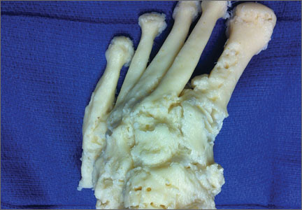
Ischiofemoral Impingement and the Utility of Full-Range-of-Motion Magnetic Resonance Imaging in Its Detection
With the first cases described in 1977, ischiofemoral impingement (IFI) is a relatively recently discovered and less known potential cause of hip pain caused by compression on the quadratus femoris muscle (QFM).1-10 These first patients, who were treated with surgical excision of the lesser trochanter, experienced symptom improvement in all 3 cases.5,7 The most widely accepted diagnostic criteria use a combination of clinical and imaging findings.1-10 Criteria most often cited in the literature include isolated edema-like signal in the QFM on magnetic resonance imaging (MRI) and ipsilateral hip pain without a known cause, such as recent trauma or infection.4,5 All studies describe QFM compression occurring as the muscle passes between the lesser trochanter of the femur and the origin of the ischial tuberosity/hamstring tendons.1-10
Several authors have sought to improve diagnostic accuracy by providing various measurements to quantify the probability of impingement.5,7,9 Although groups have proposed different thresholds, our institution currently uses values reported by Tosun and colleagues5 because theirs is the most robust sample size to date and included 50 patients with IFI.7,9 Although 5 different measurements were proposed, 2 are more commonly cited. The first is the ischiofemoral space (IFS), which is the most narrow distance between the cortex of the lesser trochanter and the cortex of the ischial tuberosity. This space should normally be greater than 1.8 cm.5 The second measurement is called the quadratus femoris space (QFS) and is the most narrow distance between the hamstring tendons and either the iliopsoas tendon or the cortex of the lesser trochanter. The QFS should normally be greater than 1.0 cm.5 However, because these measurements may depend on the hip position during imaging, full-range-of-motion (FROM) MRI may increase diagnostic yield. At our institution, patients are usually imaged supine in neutral position (with respect to internal or external rotation).
In this article, we briefly review IFI, provide an example of how FROM MRI can improve diagnostic accuracy, describe our FROM protocol, and propose an expanded definition of the impingement criteria. The patient provided written informed consent for print and electronic publication of the case details and images.
Full–Range-of-Motion MRI Technique
A 58-year-old woman with no surgical history or diagnosed inflammatory arthropathy presented to the department of physical medicine and rehabilitation with left-buttock pain radiating down the left thigh. Despite nonsurgical management with nonsteroidal anti-inflammatory medication, exercise therapy, use of a transcutaneous electrical nerve stimulator unit, and oral corticosteroid therapy, the pain continued. The patient was referred for MRI, and routine static imaging of the pelvis was performed. Although edema-like signal was present in both QFMs (Figure 1), left more than right, the measurement of the QFS and IFS did not meet all criteria for narrowing as described in previous studies. On the symptomatic left side, the IFS measured 1.5 cm and the QFS measured 1.4 cm (Figure 2). On the same side, the distance between the cortex of the greater trochanter and the cortex of the ischial tuberosity, proposed adapted IFS, measured 1.4 cm, and the distance between the cortex of the greater trochanter and the hamstring tendons origin, proposed adapted QFS, measured 1.1 cm (Figure 3). However, because of the isolated QFM edema, refractory buttock and thigh pain, and exclusion of other diagnoses (such as labral tear, bone marrow edema/stress reaction in the hip, or MRI findings of sciatic neuropathy), we determined that the patient needed evaluation of the QFS and the IFS through a full range of motion. The patient returned for the FROM MRI 16 days after the initial static MRI.
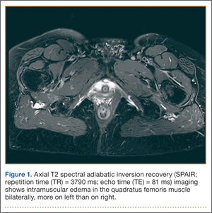
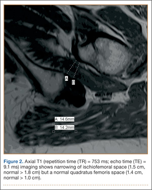
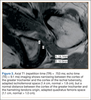
Our FROM MRI was performed on a Magnetom Skyra 3 Tesla magnet (Seimens Healthcare Global, Munich, Germany), using a body array 18-channel coil and a table spine coil. In a supine position, the patient’s imaging started with the hip in extension, adduction, and approximately 20º of internal rotation. During imaging acquisition, the patient was maintained in adduction and extension while the hip was passively externally rotated (Figure 3). A technologist assisted the patient in maintaining the position through a 60º arc of external rotation, while an axial-gradient echo sequence was used to obtain sequential images through the entire arc. Selected parameters are listed in the Table. Acquisition of the arc of motion in the axial plane requires approximately 3 minutes per hip to generate between 8 and 10 images.
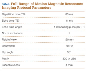
With the patient’s hip in internal rotation, narrowing between the ischium or hamstring tendons and the lesser trochanter did not meet all of the criteria described by Tosun and colleagues5 or Torriani and colleagues.7 However, when the patient shifted into external rotation, the distance between the ischial tuberosity and the greater trochanter, and between the hamstring tendons origin and the greater trochanter, significantly narrowed. The adapted IFS decreased from 3.4 cm to 1.5 cm, and the adapted QFS decreased from 3.2 cm to 0.9 cm, accounting for a 54% and 72% reduction of the adapted IFS and QFS, respectively, with maximum external rotation (Figures 4, 5).
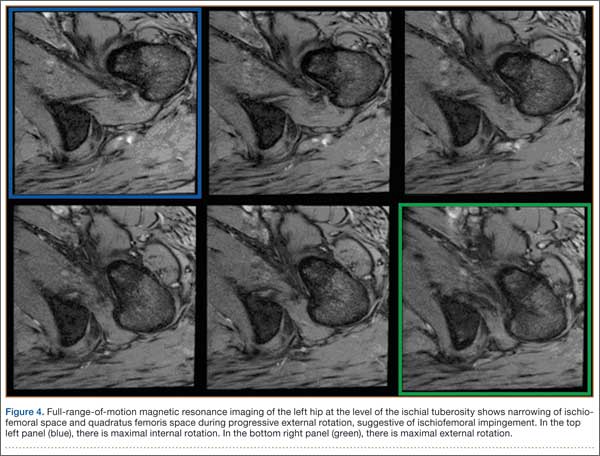
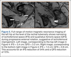
Discussion
While femoroacetabular impingement is a widely recognized and sometimes surgically treated syndrome, IFI may be overlooked as a cause of hip pain. Although IFI is traditionally described as mass effect on the QFM by the ischium/hamstring tendons origin and the lesser trochanter, we propose expansion of this criteria to include narrowing resulting from the greater trochanter in external rotation as a potential source of impingement. By use of FROM MRI, we adapted measurements previously described for IFI to evaluate for compression of the QFM by adjacent osseous and tendinous structures throughout the full range of internal/external hip rotation. In this case, FROM imaging provided evidence of possible anatomical narrowing caused by the greater trochanter, in addition to that caused by the lesser trochanter. Given that impingement may be caused by either the greater or lesser trochanters, it is prudent to perform FROM MRI in evaluating patients with suspected IFI. If FROM imaging is not feasible, static imaging in both maximal internal and external rotation may allow for better assessment. There have been no large studies conducted to assess the normal interval between the ischial tuberosity/hamstring origins and the greater trochanter.
The purpose of this report is to call attention to a source of impingement that may be undetected with static MRI, possibly leading to a missed diagnosis. While we believe this to be the first reported example of impingement involving the greater trochanter, larger studies should be conducted to explore this possible source of impingement. Information about the incidence of greater trochanteric impingement could lead to changes in our understanding of this syndrome and its management.
1. Lee S, Kim I, Lee SM, Lee J. Ischiofemoral impingement syndrome. Ann Rehabil Med. 2013;37(1):143-146.
2. Sussman WI, Han E, Schuenke MD. Quantitative assessment of the ischiofemoral space and evidence of degenerative changes in the quadratus femoris muscle. Surg Radiol Anat. 2013;35(4):273-281.
3. López-Sánchez MC, Armesto Pérez V, Montero Furelos LÁ, Vázquez-Rodríguez TR, Calvo Arrojo G, Díaz Román TM. Ischiofemoral impingement: hip pain of infrequent cause. Ischiofemoral impingement: hip pain of infrequent cause. Rheumatol Clin. 2013;9(3):186-187.
4. Viala P, Vanel D, Larbi A, Cyteval C, Laredo JD. Bilateral ischiofemoral impingement in a patient with hereditary multiple exostoses. Skeletal Radiol. 2012;41(12):1637-1640.
5. Tosun O, Algin O, Yalcin N, Cay N, Ocakoglu G, Karaoglanoglu M. Ischiofemoral impingement: evaluation with new MRI parameters and assessment of their reliability. Skeletal Radiol. 2012;41(5):575-587.
6. Ali AM, Whitwell D, Ostlere SJ. Case report: imaging and surgical treatment of a snapping hip due to ischiofemoral impingement. Skeletal Radiol. 2011;40(5):653-656.
7. Torriani M, Souto SC, Thomas BJ, Ouellette H, Bredella MA. Ischiofemoral impingement syndrome: an entity with hip pain and abnormalities of the quadratus femoris muscle. AJR Am J Roentgenol. 2009;193(1):186-190.
8. Ali AM, Teh J, Whitwell D, Ostlere S. Ischiofemoral impingement: a retrospective analysis of cases in a specialist orthopaedic centre over a four-year period. Hip Int. 2013;3(23):263-268.
9. Sussman WI, Han E, Schuenke MD. Quantitative assessment of the ischiofemoral space and evidence of degenerative changes in the quadratus femoris muscle. Surg Radiol Anat. 2013;35(4):273-281.
10. Kassarjian A. Signal abnormalities in the quadratus femoris muscle: tear or impingement? AJR Am J Roentgenol. 2008;190(6):W379.
With the first cases described in 1977, ischiofemoral impingement (IFI) is a relatively recently discovered and less known potential cause of hip pain caused by compression on the quadratus femoris muscle (QFM).1-10 These first patients, who were treated with surgical excision of the lesser trochanter, experienced symptom improvement in all 3 cases.5,7 The most widely accepted diagnostic criteria use a combination of clinical and imaging findings.1-10 Criteria most often cited in the literature include isolated edema-like signal in the QFM on magnetic resonance imaging (MRI) and ipsilateral hip pain without a known cause, such as recent trauma or infection.4,5 All studies describe QFM compression occurring as the muscle passes between the lesser trochanter of the femur and the origin of the ischial tuberosity/hamstring tendons.1-10
Several authors have sought to improve diagnostic accuracy by providing various measurements to quantify the probability of impingement.5,7,9 Although groups have proposed different thresholds, our institution currently uses values reported by Tosun and colleagues5 because theirs is the most robust sample size to date and included 50 patients with IFI.7,9 Although 5 different measurements were proposed, 2 are more commonly cited. The first is the ischiofemoral space (IFS), which is the most narrow distance between the cortex of the lesser trochanter and the cortex of the ischial tuberosity. This space should normally be greater than 1.8 cm.5 The second measurement is called the quadratus femoris space (QFS) and is the most narrow distance between the hamstring tendons and either the iliopsoas tendon or the cortex of the lesser trochanter. The QFS should normally be greater than 1.0 cm.5 However, because these measurements may depend on the hip position during imaging, full-range-of-motion (FROM) MRI may increase diagnostic yield. At our institution, patients are usually imaged supine in neutral position (with respect to internal or external rotation).
In this article, we briefly review IFI, provide an example of how FROM MRI can improve diagnostic accuracy, describe our FROM protocol, and propose an expanded definition of the impingement criteria. The patient provided written informed consent for print and electronic publication of the case details and images.
Full–Range-of-Motion MRI Technique
A 58-year-old woman with no surgical history or diagnosed inflammatory arthropathy presented to the department of physical medicine and rehabilitation with left-buttock pain radiating down the left thigh. Despite nonsurgical management with nonsteroidal anti-inflammatory medication, exercise therapy, use of a transcutaneous electrical nerve stimulator unit, and oral corticosteroid therapy, the pain continued. The patient was referred for MRI, and routine static imaging of the pelvis was performed. Although edema-like signal was present in both QFMs (Figure 1), left more than right, the measurement of the QFS and IFS did not meet all criteria for narrowing as described in previous studies. On the symptomatic left side, the IFS measured 1.5 cm and the QFS measured 1.4 cm (Figure 2). On the same side, the distance between the cortex of the greater trochanter and the cortex of the ischial tuberosity, proposed adapted IFS, measured 1.4 cm, and the distance between the cortex of the greater trochanter and the hamstring tendons origin, proposed adapted QFS, measured 1.1 cm (Figure 3). However, because of the isolated QFM edema, refractory buttock and thigh pain, and exclusion of other diagnoses (such as labral tear, bone marrow edema/stress reaction in the hip, or MRI findings of sciatic neuropathy), we determined that the patient needed evaluation of the QFS and the IFS through a full range of motion. The patient returned for the FROM MRI 16 days after the initial static MRI.
Our FROM MRI was performed on a Magnetom Skyra 3 Tesla magnet (Seimens Healthcare Global, Munich, Germany), using a body array 18-channel coil and a table spine coil. In a supine position, the patient’s imaging started with the hip in extension, adduction, and approximately 20º of internal rotation. During imaging acquisition, the patient was maintained in adduction and extension while the hip was passively externally rotated (Figure 3). A technologist assisted the patient in maintaining the position through a 60º arc of external rotation, while an axial-gradient echo sequence was used to obtain sequential images through the entire arc. Selected parameters are listed in the Table. Acquisition of the arc of motion in the axial plane requires approximately 3 minutes per hip to generate between 8 and 10 images.
With the patient’s hip in internal rotation, narrowing between the ischium or hamstring tendons and the lesser trochanter did not meet all of the criteria described by Tosun and colleagues5 or Torriani and colleagues.7 However, when the patient shifted into external rotation, the distance between the ischial tuberosity and the greater trochanter, and between the hamstring tendons origin and the greater trochanter, significantly narrowed. The adapted IFS decreased from 3.4 cm to 1.5 cm, and the adapted QFS decreased from 3.2 cm to 0.9 cm, accounting for a 54% and 72% reduction of the adapted IFS and QFS, respectively, with maximum external rotation (Figures 4, 5).
Discussion
While femoroacetabular impingement is a widely recognized and sometimes surgically treated syndrome, IFI may be overlooked as a cause of hip pain. Although IFI is traditionally described as mass effect on the QFM by the ischium/hamstring tendons origin and the lesser trochanter, we propose expansion of this criteria to include narrowing resulting from the greater trochanter in external rotation as a potential source of impingement. By use of FROM MRI, we adapted measurements previously described for IFI to evaluate for compression of the QFM by adjacent osseous and tendinous structures throughout the full range of internal/external hip rotation. In this case, FROM imaging provided evidence of possible anatomical narrowing caused by the greater trochanter, in addition to that caused by the lesser trochanter. Given that impingement may be caused by either the greater or lesser trochanters, it is prudent to perform FROM MRI in evaluating patients with suspected IFI. If FROM imaging is not feasible, static imaging in both maximal internal and external rotation may allow for better assessment. There have been no large studies conducted to assess the normal interval between the ischial tuberosity/hamstring origins and the greater trochanter.
The purpose of this report is to call attention to a source of impingement that may be undetected with static MRI, possibly leading to a missed diagnosis. While we believe this to be the first reported example of impingement involving the greater trochanter, larger studies should be conducted to explore this possible source of impingement. Information about the incidence of greater trochanteric impingement could lead to changes in our understanding of this syndrome and its management.
1. Lee S, Kim I, Lee SM, Lee J. Ischiofemoral impingement syndrome. Ann Rehabil Med. 2013;37(1):143-146.
2. Sussman WI, Han E, Schuenke MD. Quantitative assessment of the ischiofemoral space and evidence of degenerative changes in the quadratus femoris muscle. Surg Radiol Anat. 2013;35(4):273-281.
3. López-Sánchez MC, Armesto Pérez V, Montero Furelos LÁ, Vázquez-Rodríguez TR, Calvo Arrojo G, Díaz Román TM. Ischiofemoral impingement: hip pain of infrequent cause. Ischiofemoral impingement: hip pain of infrequent cause. Rheumatol Clin. 2013;9(3):186-187.
4. Viala P, Vanel D, Larbi A, Cyteval C, Laredo JD. Bilateral ischiofemoral impingement in a patient with hereditary multiple exostoses. Skeletal Radiol. 2012;41(12):1637-1640.
5. Tosun O, Algin O, Yalcin N, Cay N, Ocakoglu G, Karaoglanoglu M. Ischiofemoral impingement: evaluation with new MRI parameters and assessment of their reliability. Skeletal Radiol. 2012;41(5):575-587.
6. Ali AM, Whitwell D, Ostlere SJ. Case report: imaging and surgical treatment of a snapping hip due to ischiofemoral impingement. Skeletal Radiol. 2011;40(5):653-656.
7. Torriani M, Souto SC, Thomas BJ, Ouellette H, Bredella MA. Ischiofemoral impingement syndrome: an entity with hip pain and abnormalities of the quadratus femoris muscle. AJR Am J Roentgenol. 2009;193(1):186-190.
8. Ali AM, Teh J, Whitwell D, Ostlere S. Ischiofemoral impingement: a retrospective analysis of cases in a specialist orthopaedic centre over a four-year period. Hip Int. 2013;3(23):263-268.
9. Sussman WI, Han E, Schuenke MD. Quantitative assessment of the ischiofemoral space and evidence of degenerative changes in the quadratus femoris muscle. Surg Radiol Anat. 2013;35(4):273-281.
10. Kassarjian A. Signal abnormalities in the quadratus femoris muscle: tear or impingement? AJR Am J Roentgenol. 2008;190(6):W379.
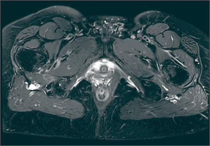
Neonatal Physeal Separation of Distal Humerus During Cesarean Section
Physeal separation of the distal humerus in a newborn is a rare and severe injury that requires immediate treatment. This fracture was reported as an extremely rare complication of cesarean section.1 The correct diagnosis can be established by clinical and radiologic findings. However, this injury can be easily overlooked and misdiagnosed. Presentation often involves swelling, tenderness, and agitation with movement of the elbow.
We report a case in which neonatal physeal separation of the distal humerus occurred during cesarean section. The diagnosis was based on clinical and radiologic/arthrographic findings and treated with closed reduction and percutaneous fixation. The patient’s guardian provided written informed consent for print and electronic publication of this case report.
Case Report
A full-term (40-week gestation) male neonate weighing 3690 g was born through cesarean section at the mother’s request. Apgar score was 9 at 1 minute and 10 at 5 minutes. The vertex position of the fetus was confirmed with preoperative ultrasonography. This was the mother’s first pregnancy and an in vitro fertilization. On his second day of life, the patient was referred to the orthopedic department for evaluation of local swelling and diminished spontaneous motion of the right elbow.
Examination revealed local tenderness and swelling in the anterior and lateral aspects of the elbow. Passive elbow range of motion (ROM) caused agitation, and elbow instability was present. A complete neurovascular examination was performed, and neurovascular injury and compartment syndrome were ruled out. Hematologic workup showed no signs of septic arthritis. Radiographs showed posteromedial displacement of the humeroulnar joint. The patient was placed in a long-arm splint, and no reduction was attempted initially.
The patient was taken to the operating room the same day. With the patient under general anesthesia, an arthrogram of the right elbow was obtained. It showed posteromedial displacement of the distal humeral epiphysis (Figure 1A). Closed reduction was performed, and the quality of the reduction was confirmed by intraoperative imaging. Percutaneously, a single 2-mm Kirschner wire (K-wire) was placed in an oblique fashion from the inferolateral aspect of the distal fragment to the contralateral metaphysis of the humerus (Figure 1B). The patient was put in a long-arm splint with the elbow flexed at 90° and the forearm in midpronation.
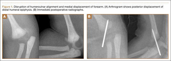
Follow-up visits were scheduled for 1 week, 3 weeks, and 5 weeks after surgery. Three weeks after surgery, callus formation was confirmed, and the K-wire was removed. Five weeks after surgery, the long-arm splint was removed.
At 6-month follow-up, the patient was pain-free and had full elbow ROM, and radiographs (Figures 2A, 2B) confirmed anatomical restoration of the fracture.
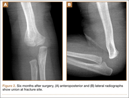
Discussion
Madsen2 reported the incidence of birth-related long-bone fractures, including fractures of the humerus, the femur, and the tibia (< 0.1%). According to that review, only 1 of 105,119 patients sustained traumatic physeal separation of the distal humerus.
Different mechanisms have been described for this rare fracture. As the physeal region is the weakest part of the distal humerus, it is prone to injury by rotational shear forces,3,4 hyperextension of the elbow, or a backward thrust on the forearm with the elbow flexed.5 Excessive traction applied during cesarean delivery might cause physeal separation, which was the possible cause in the present case. Most patients have a complicated birth history.
This injury should be suspected in an irritable newborn with swelling, tenderness, and reduced mobility of the upper extremity. Osteomyelitis and septic arthritis should be considered in the differential diagnosis. Brachial plexus injury and dislocation of the elbow joint should also be kept in mind. Child abuse and metabolic bone diseases (eg, osteogenesis imperfecta) should also be considered.
Anteroposterior and lateral plain radiographs of the elbow usually establish the diagnosis. Alteration of humeroulnar alignment and displacement of the proximal forearm are the key points leading to the diagnosis.
The cartilaginous part of the distal humerus and humeroulnar alignment can be demonstrated by ultrasonography.6 Magnetic resonance imaging (MRI) can be helpful in diagnosis but is seldom required,7 and the sedation or general anesthesia used is a disadvantage. Arthrography is useful not only in diagnosis but in determining the quality of the reduction.8 An arthrogram may show that open reduction is unnecessary.
Treatment differs widely. In neonates, who have a tremendous healing capability, this fracture almost always heals uneventfully. An effective treatment method is closed reduction and cast immobilization. However, valgus malalignment and limited elbow ROM were noted in 5% of the patients treated with this method.4
Jacobsen and colleagues4 reported on 6 neonates who sustained traumatic separation of the distal epiphysis of the humerus at birth and who were treated with casting with or without closed reduction. The authors described good results. One patient had varus malalignment, which was attributed to fragment internal rotation caused by rotational instability.
As our patient’s instability was noted during surgery, we performed percutaneous pinning after arthrography-assisted closed reduction. We considered using 2 lateral pins for fixation, but, after the first pin was placed, fluoroscopic stress testing with the patient under anesthesia demonstrated adequate stability. A second, smaller pin could have been used to control rotation, if needed. Medial pin placement that avoids the ulnar nerve is difficult in the newborn elbow; medial pins should probably be avoided in the newborn, if possible.
Early diagnosis and treatment are essential. Late diagnosis was reported to lead to complications such as varus deformity and restriction of joint ROM.4
Our patient healed without any complications and achieved full ROM. Long-term follow-up is needed to diagnose any physeal bar that might lead to secondary deformities.
Conclusion
Cesarean section is reported to reduce birth complications, but it might cause fractures of the femur and humerus.1 Avoiding application of excessive traction to the forearm can prevent physeal separation of the distal humerus. This entity should be kept in mind as a potential complication of cesarean section. Arthrography is helpful in treatment and may help avoid unnecessary open reduction.
1. Sabat D, Maini L, Gautam VK. Neonatal separation of distal humeral epiphysis during caesarean section: a case report. J Orthop Surg (Hong Kong). 2011;19(3):376-378.
2. Madsen ET. Fractures of the extremities in the newborn. Acta Obstet Gynecol Scand. 1955;34(1):41-74.
3. Peterson HA. Physeal fractures. In: Morrey BF, ed. The Elbow and Its Disorders. Philadelphia, PA: Saunders; 1985:222-236.
4. Jacobsen S, Hansson G, Nathorst-Westfelt J. Traumatic separation of the distal epiphysis of the humerus sustained at birth. J Bone Joint Surg Br. 2009;91(6):797-802.
5. Siffert RS. Displacement of distal humeral epiphysis in the newborn. J Bone Joint Surg Am. 1963;45(1):165-169.
6. Davidson RS, Markowitz RI, Dormans J, Drummond DS. Ultrasonographic evaluation of the elbow in infants and young children after suspected trauma. J Bone Joint Surg Am. 1994;76(12):1804-1813.
7. Sawant MR, Narayanan S, O‘Neill K, Hudson I. Distal humeral epiphysis fracture separation in neonates—diagnosis using MRI scan. Injury. 2002;33(2):179-181.
8. Akbarnia BA, Silberstein MJ, Rende RJ, Graviss ER, Luisiri A. Arthrography in the diagnosis of fractures of the distal end of the humerus in infants. J Bone Joint Surg Am. 1986;68(4):599-602.
Physeal separation of the distal humerus in a newborn is a rare and severe injury that requires immediate treatment. This fracture was reported as an extremely rare complication of cesarean section.1 The correct diagnosis can be established by clinical and radiologic findings. However, this injury can be easily overlooked and misdiagnosed. Presentation often involves swelling, tenderness, and agitation with movement of the elbow.
We report a case in which neonatal physeal separation of the distal humerus occurred during cesarean section. The diagnosis was based on clinical and radiologic/arthrographic findings and treated with closed reduction and percutaneous fixation. The patient’s guardian provided written informed consent for print and electronic publication of this case report.
Case Report
A full-term (40-week gestation) male neonate weighing 3690 g was born through cesarean section at the mother’s request. Apgar score was 9 at 1 minute and 10 at 5 minutes. The vertex position of the fetus was confirmed with preoperative ultrasonography. This was the mother’s first pregnancy and an in vitro fertilization. On his second day of life, the patient was referred to the orthopedic department for evaluation of local swelling and diminished spontaneous motion of the right elbow.
Examination revealed local tenderness and swelling in the anterior and lateral aspects of the elbow. Passive elbow range of motion (ROM) caused agitation, and elbow instability was present. A complete neurovascular examination was performed, and neurovascular injury and compartment syndrome were ruled out. Hematologic workup showed no signs of septic arthritis. Radiographs showed posteromedial displacement of the humeroulnar joint. The patient was placed in a long-arm splint, and no reduction was attempted initially.
The patient was taken to the operating room the same day. With the patient under general anesthesia, an arthrogram of the right elbow was obtained. It showed posteromedial displacement of the distal humeral epiphysis (Figure 1A). Closed reduction was performed, and the quality of the reduction was confirmed by intraoperative imaging. Percutaneously, a single 2-mm Kirschner wire (K-wire) was placed in an oblique fashion from the inferolateral aspect of the distal fragment to the contralateral metaphysis of the humerus (Figure 1B). The patient was put in a long-arm splint with the elbow flexed at 90° and the forearm in midpronation.
Follow-up visits were scheduled for 1 week, 3 weeks, and 5 weeks after surgery. Three weeks after surgery, callus formation was confirmed, and the K-wire was removed. Five weeks after surgery, the long-arm splint was removed.
At 6-month follow-up, the patient was pain-free and had full elbow ROM, and radiographs (Figures 2A, 2B) confirmed anatomical restoration of the fracture.
Discussion
Madsen2 reported the incidence of birth-related long-bone fractures, including fractures of the humerus, the femur, and the tibia (< 0.1%). According to that review, only 1 of 105,119 patients sustained traumatic physeal separation of the distal humerus.
Different mechanisms have been described for this rare fracture. As the physeal region is the weakest part of the distal humerus, it is prone to injury by rotational shear forces,3,4 hyperextension of the elbow, or a backward thrust on the forearm with the elbow flexed.5 Excessive traction applied during cesarean delivery might cause physeal separation, which was the possible cause in the present case. Most patients have a complicated birth history.
This injury should be suspected in an irritable newborn with swelling, tenderness, and reduced mobility of the upper extremity. Osteomyelitis and septic arthritis should be considered in the differential diagnosis. Brachial plexus injury and dislocation of the elbow joint should also be kept in mind. Child abuse and metabolic bone diseases (eg, osteogenesis imperfecta) should also be considered.
Anteroposterior and lateral plain radiographs of the elbow usually establish the diagnosis. Alteration of humeroulnar alignment and displacement of the proximal forearm are the key points leading to the diagnosis.
The cartilaginous part of the distal humerus and humeroulnar alignment can be demonstrated by ultrasonography.6 Magnetic resonance imaging (MRI) can be helpful in diagnosis but is seldom required,7 and the sedation or general anesthesia used is a disadvantage. Arthrography is useful not only in diagnosis but in determining the quality of the reduction.8 An arthrogram may show that open reduction is unnecessary.
Treatment differs widely. In neonates, who have a tremendous healing capability, this fracture almost always heals uneventfully. An effective treatment method is closed reduction and cast immobilization. However, valgus malalignment and limited elbow ROM were noted in 5% of the patients treated with this method.4
Jacobsen and colleagues4 reported on 6 neonates who sustained traumatic separation of the distal epiphysis of the humerus at birth and who were treated with casting with or without closed reduction. The authors described good results. One patient had varus malalignment, which was attributed to fragment internal rotation caused by rotational instability.
As our patient’s instability was noted during surgery, we performed percutaneous pinning after arthrography-assisted closed reduction. We considered using 2 lateral pins for fixation, but, after the first pin was placed, fluoroscopic stress testing with the patient under anesthesia demonstrated adequate stability. A second, smaller pin could have been used to control rotation, if needed. Medial pin placement that avoids the ulnar nerve is difficult in the newborn elbow; medial pins should probably be avoided in the newborn, if possible.
Early diagnosis and treatment are essential. Late diagnosis was reported to lead to complications such as varus deformity and restriction of joint ROM.4
Our patient healed without any complications and achieved full ROM. Long-term follow-up is needed to diagnose any physeal bar that might lead to secondary deformities.
Conclusion
Cesarean section is reported to reduce birth complications, but it might cause fractures of the femur and humerus.1 Avoiding application of excessive traction to the forearm can prevent physeal separation of the distal humerus. This entity should be kept in mind as a potential complication of cesarean section. Arthrography is helpful in treatment and may help avoid unnecessary open reduction.
1. Sabat D, Maini L, Gautam VK. Neonatal separation of distal humeral epiphysis during caesarean section: a case report. J Orthop Surg (Hong Kong). 2011;19(3):376-378.
2. Madsen ET. Fractures of the extremities in the newborn. Acta Obstet Gynecol Scand. 1955;34(1):41-74.
3. Peterson HA. Physeal fractures. In: Morrey BF, ed. The Elbow and Its Disorders. Philadelphia, PA: Saunders; 1985:222-236.
4. Jacobsen S, Hansson G, Nathorst-Westfelt J. Traumatic separation of the distal epiphysis of the humerus sustained at birth. J Bone Joint Surg Br. 2009;91(6):797-802.
5. Siffert RS. Displacement of distal humeral epiphysis in the newborn. J Bone Joint Surg Am. 1963;45(1):165-169.
6. Davidson RS, Markowitz RI, Dormans J, Drummond DS. Ultrasonographic evaluation of the elbow in infants and young children after suspected trauma. J Bone Joint Surg Am. 1994;76(12):1804-1813.
7. Sawant MR, Narayanan S, O‘Neill K, Hudson I. Distal humeral epiphysis fracture separation in neonates—diagnosis using MRI scan. Injury. 2002;33(2):179-181.
8. Akbarnia BA, Silberstein MJ, Rende RJ, Graviss ER, Luisiri A. Arthrography in the diagnosis of fractures of the distal end of the humerus in infants. J Bone Joint Surg Am. 1986;68(4):599-602.
The Role of Computed Tomography for Postoperative Evaluation of Percutaneous Sacroiliac Screw Fixation and Description of a “Safe Zone”
Pelvic injuries account for 3% of all skeletal fractures.1 Injury to the sacroiliac (SI) joint is frequently associated with unstable pelvic ring fractures, which are potentially life-threatening injuries. Surgical fixation of these injuries is preferred to nonoperative treatment given the potential for improved reduction and early mobilization and weight-bearing, thereby decreasing perioperative morbidity and improving functional outcome.2
The classic method of surgical fixation of the SI joint consisted of open reduction and internal fixation. This method carried a substantial risk for large dissection, iatrogenic nerve injury, and increased blood loss to the already traumatized patient.3 Percutaneous fixation allows for a shorter operating time, decreased soft-tissue stripping, and decreased blood loss compared with a traditional open procedure.4 However, posterior pelvic anatomy is complex and variable, and reports have found screw misplacements as high as 24%5 and neurologic complication rates up to 18%.6-9
Various imaging modalities, including fluoroscopy,5 computed tomography (CT),6-7 fluoroscopic CT, and computer-assisted techniques5,9 have been used to achieve proper screw placement. Conventional fluoroscopy is the standard for intraoperative screw placement. However, acceptable reduction of the SI joint and proper implantation of the screws without perforation of the neural foramina is challenging, especially when coupled with difficulties of fluoroscopic imaging and variations in pelvic anatomy.
Sacral dysplasia has been reported to occur in up to 20% to 40% of the population and has significant implications in patients indicated for iliosacral screw placement.10 Incorrect placement of iliosacral screws may result in iatrogenic neurovascular complications.11-13 Malpositioned screws using fluoroscopic guidance have been reported in 2% to 15% of patients with an incidence of neurologic compromise between 0.5% and 7.7%. As little as 4° of misdirection can result in damage to neurovascular structures.14
At our institution, we routinely obtained postoperative CT to evaluate the placement of SI screws. The objective of this retrospective study is to evaluate the rate of revision surgery of percutaneous SI screw fixation, to determine whether CT is an accurate tool for evaluation of the reduction and the need for revision surgery, and to decide if any violation of the neural foramina is safe.
Materials and Methods
After institutional review board approval, we retrospectively reviewed and evaluated medical records and radiographs of all patients who sustained unstable pelvic ring fractures between July 1, 2005, and June 30, 2010. We identified all patients who were treated with closed reductions and percutaneous iliosacral screw fixation, according to the method described by Routt in 1995.4 We excluded all pelvic fractures in patients who underwent open reduction for the posterior injury or did not have percutaneous SI screws placed, those with spinal injury, and those without follow-up. Of the 46 patients who met the inclusion criteria were 26 men and 20 women with a mean age of 42 years (range, 16 to 73 years). Motor vehicle accidents accounted for 13 cases; 19 were crush injuries and 14 were falls from height. Seventeen patients (37%) met the radiographic criteria for sacral dysmorphism. Forty-two of the 46 patients were polytrauma patients with associated musculoskeletal injuries and/or abdominal, chest, or head injuries.
Six patients presented with some neurologic deficit at the time of injury; all fractures were closed. The initial imaging study included plain anteroposterior (AP), inlet, and outlet radiographs of the pelvis and a pelvic CT scan. Using the classification of Young and Burgess,15 there were 3 vertical shear injuries, 13 lateral compression–type injuries, 17 anterior-posterior–type injuries, 7 sacral fractures, and 6 combination- or unclassifiable-type pelvic injuries. Of the sacral fractures, there were 3 Denis zone 1, 3 Denis zone 2, and 1 Denis zone 3.
The pelvic CT scan included the entire pelvis from the ilium to the ischial tuberosities. Each scan consisted of either a 5.0-mm or a 2.5-mm sequential axial image. A picture archiving and communication system (PACS) workstation using Centricity version 2.1 (GE Medical Systems, Waukesha, Wisconsin) was used to analyze each scan with a bone algorithm. On PACS, each initial displacement was characterized by the amount of SI joint widening at the level of the S1 and was measured using digital calipers.
Surgery
Mean time to surgery was 4 days (range, 2 to 15 days) after the injury. A total of 51 SI screws were implanted in 46 patients. We achieved closed reduction of the posterior pelvic ring by various techniques, including compression with percutaneous partially threaded screw fixation. In the cases in which the posterior ring lesion was associated with a pure pubic symphysis disruption, the anterior pelvis was initially reduced and stabilized with small-fragment plate fixation (Synthes, Inc, Paoli, Pennsylvania). The posterior complex was stabilized with 1 screw in 41 patients, 2 cases required a transiliac screw, and 2 screws (S1 and S2) were placed in each of the remaining 3 cases. Definitive stabilization of the posterior pelvis was achieved with percutaneous, partially threaded 7.3- or 7.5-mm–diameter cannulated screws (Synthes, Inc, and Zimmer Inc, Warsaw, Indiana, respectively) in 42 fractures and 6.5-mm screws (Synthes, Inc) in 4 fractures. In 11 cases where the fracture was through the sacrum, fully threaded cannulated screws were used to avoid compression. Screw insertion was performed under fluoroscopic guidance with inlet, outlet, and lateral sacral views. One of 2 fellowship-trained trauma surgeons performed the surgeries. Rehabilitation plans were customized to each patient based on concomitant injuries.
Postoperative Assessment
AP, lateral sacral, and inlet and outlet postoperative radiographs were taken in all cases within 24 hours after surgery. Pelvic CT was also obtained within 24 hours of surgery to review reduction and screw placement.
Using the measurement tool on the PACS system, we measured the penetration of the screw into the foramen. Screws were graded as intraosseous (completely contained within the sacral bone), skived (less than 2 mm of partial penetration into the S1 foramen), or extruded (the screw not contained by the bone). Screw penetration of the S1 was evaluated on the radiographic images as well as the axial images of the CT scans.
After surgery, the senior orthopedic resident and attending surgeon performed and documented detailed neurologic evaluations. They reviewed the medical record for neurologic deficit following surgical fixation.
Results
The mean follow-up time was 12 months (range, 8 months to 2 years). Two patients expired secondary to associated injuries. There were no early deaths related to the pelvic surgery. Stable fixation, including bone or ligamentous healing, as well as full weight-bearing status, was noted in every case. No case exhibited loss of reduction or implant failure or infection.
According to Matta’s criteria of anatomic reduction within 1 cm, all patients were found to have satisfactory reductions.7 Six of 46 patients had documented preoperative neurologic deficits. After percutaneous screw fixation, 10 of 46 patients had postoperative neurologic deficit, 2 of which were unchanged from preoperative evaluation. Of the 8 patients with new/altered postoperative neurologic deficit, CT showed neural foramen penetration greater than 2.1 mm in only 2 patients. Both patients underwent screw revision, resulting in improved neurologic deficit. The remaining 4 patients did not have foramen penetration and improved their neurologic function over the course of 2 weeks with return to presurgical status by 6 weeks without necessitating screw removal.
Twenty-three of the 51 screws (45%) had some violation of the S1 foramen on the CT. There were 17 patients with dysmorphic sacrums in which 21 S1 screws were placed. Eleven of 21 (52%) screws showed some penetration of the S1 foramen on CT. There were 29 patients with normal sacral morphology in which 30 S1 screws were placed. Twelve of 30 (40%) screws penetrated the S1 foramen. All violations were in the superior one-third position of the foramen. Two of 46 (4%; 1 with dysmorphism, 1 without) had a new neurologic deficit associated with the surgery (Table). CT showed sacral foramen penetration, and both screws were revised with a better neurologic examination.
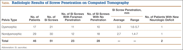
High-resolution CTs were obtained in 32 patients, while 14 patients underwent the standard 5.0-mm–cut CTs. Of the 32 patients in which a 2.5-mm high-resolution CT was obtained, 20 (62.5%) had evidence of screw penetration (Figures 1, 2). All violations of the S1 neural foramen were in the superior portion of the foramen.
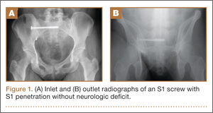
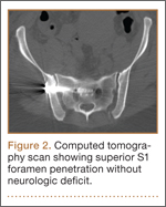
When compared with patients who had a 5.0-mm CT, the patients who underwent a high-resolution CT were more likely to show neural foramen penetration (P = .3). The average screw penetration into the S1 neural foramen measured 3.3 mm (range, 1.6-5.7 mm) in dysmorphic sacrum and 2.7 mm (range, 1.4-7 mm) in normal sacrum. However, in our study, any foramen penetration of less than 2.1 mm on CT did not result in neurologic deficit.
Discussion
Pelvic fractures are fairly common and represent approximately 5% of all trauma admissions and 3% of all skeletal fractures nationwide.1 The current treatment for SI disruption is either nonoperative or operative. Surgical fixation is technically demanding and surgeons often need a long learning curve to acquire the demanding technique because of the limitations of radiographic visualization of the relevant landmarks.16
Letournel17 developed the technique for iliosacral screw fixation for the treatment of posterior pelvic ring injuries, where 1 or 2 large screws (6.5-7.3 mm in diameter) are inserted under fluoroscopic guidance through the ilium, across the SI articulation, and into the superior sacral vertebral bodies using percutaneous techniques. Currently, the standard procedure to accomplish the percutaneous placement of iliosacral screws derives mainly from the technique described by Matta with the C-arm fluoroscopy visualizing the pelvis in 3 views: strict AP, inlet, and outlet views.7
Routt and colleagues4 recommend a strict lateral view of the sacrum, particularly when crossing the narrow zone of the sacral alar. They reported high union rates and accurate placement of the screws.4 There are limitations to the use of biplanar fluoroscopy because the intraoperative images are not orthogonal, with the average arc (67º) between the ideal inlet and outlet. However, because of the variability in sacral anatomy, CT guidance was recommended by others.2,6,8,18 Operating in a CT suite had other complications. Misinterpretation of CT led to “in-out-in” screws, which resulted in neurapraxia.
In our study, we used the technique described by Matta and colleagues for placement of the screws and performed a postoperative CT to evaluate screw placement and to assess pelvic reduction.7 We had a high penetration rate using CT, which increased with better resolution, even though none of the radiographs showed any obvious evidence of misplacement of the screws. Ebraheim and colleagues6 described the relationship of the S1 nerve root in its neural foramen and found it to be approximately 8.7 mm inferior and 7.8 mm medial to the starting point for a pedicle screw. Given these numbers, it is possible that a large amount of skiving can be tolerated contingent on an adequate reduction of the SI joint.
Because of our high rates of skiving and low rates of neurologic deficit, a new “safe zone” for screw insertion can be expanded to include skiving of the S1 neural foramen up to 3 mm without fear of nerve root injury. However, drilling and screw insertion at higher speeds can also cause neurologic injury secondary to thermal injury or soft tissue being caught up in a rotating drill/screw.
Evaluation of placement of percutaneous SI screw placement in our study resulted in neural foramen penetration in 43% of SI screws, which is higher than other studies.14,19,20 Our study showed that screw penetration up to 2 mm does not correlate with neurologic deficit. Iatrogenic neurologic deficit secondary to perforation of the foramina occurred in only 1 patient. Penetration of the foramina in all cases was in the superior portion of the foramen. We propose that there is a safe zone within the S1 neural foramen, and small amounts of penetration in the superior one-third of the foramen on axial CT images do not correlate with neurologic deficit. This potential safe zone is predicated on adequate reduction of the SI joint.
Neural foramen penetration shown on postoperative CT does not necessarily correlate with neurologic deficit. A postoperative CT is not indicated unless there are findings of a postoperative nerve injury. Our ideal screw placement skives the superior S1 foramen allowing for a larger screw diameter in a safe zone.
CT-guided placement has been proposed; however, concerns about radiation exposure, cost, and feasibility with similar outcomes compared with fluoroscopic-guided screw placement has resulted in its falling out of favor.
Iatrogenic nerve injuries are reported to occur in 0% to 6% of all percutaneous SI screw placement.14,21 Risk factors for iatrogenic nerve injury while using fluoroscopic guidance include sacral morphologic abnormalities, presence of intestinal gas, or contrast.22 Although these may be minimized with proper use of fluoroscopy, obtaining anatomic reduction as well as a thorough understanding of the pelvic morphology, the surgeon must be prepared to obtain further studies, such as a CT scan, if there is postoperative neurologic deficit.
Based on our findings, we do not routinely obtain a postoperative CT for SI screw placement, unless there is concern for malreduction or there is neurologic deficit. We also believe that up to 2 mm of foramen penetration is safe and does not result in neurologic deficit.
1. Failinger MS, McGanity PL. Unstable fractures of the pelvic ring. J Bone and Joint Surg Am. 1992;74(5):781-791.
2. Smith HE, Yuan PS, Sasso R, Papadopolous S, Vaccaro AR. An evaluation of image-guided technologies in the placement of percutaneous iliosacral screws. Spine (Phila Pa 1976). 2006;31(2):234-238.
3. Judet R, Judet J, Letournel E. Fractures of the acetabulum: classification and surgical approaches for open reduction. Preliminary report. J Bone Joint Surg Am. 1964;46(16):1615-1646.
4. Routt ML Jr, Kregor PJ, Simonian PT, Mayo KA. Early results of percutaneous iliosacral screws placed with the patient in the supine position. J Orthop Trauma. 1995;9(3):207-214.
5. Tonetti J, Carrat L, Blendea S, et al. Clinical results of percutaneous pelvic surgery. Computer assisted surgery using ultrasound compared to standard fluoroscopy. Comput Aided Surg. 2001;6(4):204-211.
6. Ebraheim NA, Coombs R, Jackson WT, Rusin JJ. Percutaneous computed tomography-guided stabilization of posterior pelvic fractures. Clin Orthop. 1994;(307):222-228.
7. Keating JF, Werier J, Blachut P, et al. Early fixation of the vertically unstable pelvis: the role of iliosacral screw fixation of the posterior lesion. J Orthop Trauma. 1999;13(2):107-113.
8. Webb LX, de Araujo W, Donofrio P, et al. Electromyography monitoring for percutaneous placement of iliosacral screws. J Orthop Trauma. 2000;14(4):245-254.
9. Barrick EF, O’Mara JW, Lane HE 3rd. Iliosacral screw insertion using computer-assisted CT image guidance: a laboratory study. Comput Aided Surg. 1998;3(6):289-296.
10. Routt ML Jr, Simonian PT, Agnew SG, Mann FA. Radiographic recognition of the sacral alar slope for optimal placement of iliosacral screws: a cadaveric and clinical study. J Orthop Trauma. 1996;10(3):171-177.
11. Altman DT, Jones CB, Routt ML Jr. Superior gluteal artery injury during iliosacral screw placement. J Orthop Trauma. 1999;13(3):220-227.
12. Stephen DJ. Pseudoaneurysm of the superior gluteal arterial system: an unusual cause of pain after a pelvic fracture. J Trauma. 1997;43(1):146-149.
13. Stöckle U, König B, Hofstetter R, Nolte LP, Haas NP. [Navigation assisted by image conversion. An experimental study on pelvic screw fixation]
[in German]. Unfallchirurg. 2001;104(3):215-220.
14. Templeman D, Schmidt A, Freese J, Weisman I, et al. Proximity of iliosacral screws to neurovascular structures after internal fixation. Clin Orthop. 1996;(329):194-198.
15. Young JW, Burgess AR, Brumback RJ, Poka A. Pelvic fractures: value of plain radiography in early assessment and management. Radiology. 1986;160(2):445-451.
16. Graves ML, Routt ML Jr. Iliosacral screw placement: are uniplanar changes realistic based on standard fluoroscopic imaging? J Trauma. 2011;7(1):204-208.
17. Letournel E. Pelvic fractures. Injury. 1978;10(2):145-148.
18. Blake-Toker AM, Hawkins L, Nadalo L, et al. CT guided percutaneous fixation of sacroiliac fractures in trauma patients. J Trauma. 2001;51(6):1117-1121.
19. Hinsche AF, Giannoudis PV, Smith RM. Fluoroscopy-based multiplanar image guidance for insertion of sacroiliac screws. Clin Orthop. 2002;(395):135-144.
20. van den Bosch EW, van Zwienen CM, van Vugt AB. Fluoroscopic positioning of sacroiliac screws in 88 patients. J Trauma. 2002;53(1):44-48.
21. Cole JD, Blum DA, Ansel LJ. Outcome after fixation of unstable posterior pelvic ring injuries. Clin Orthop. 1996;(329):160-179.
22. Routt ML Jr, Simonian PT. Closed reduction and percutaneous skeletal fixation of sacral fractures. Clin Orthop. 1996;(329):121-128.
Pelvic injuries account for 3% of all skeletal fractures.1 Injury to the sacroiliac (SI) joint is frequently associated with unstable pelvic ring fractures, which are potentially life-threatening injuries. Surgical fixation of these injuries is preferred to nonoperative treatment given the potential for improved reduction and early mobilization and weight-bearing, thereby decreasing perioperative morbidity and improving functional outcome.2
The classic method of surgical fixation of the SI joint consisted of open reduction and internal fixation. This method carried a substantial risk for large dissection, iatrogenic nerve injury, and increased blood loss to the already traumatized patient.3 Percutaneous fixation allows for a shorter operating time, decreased soft-tissue stripping, and decreased blood loss compared with a traditional open procedure.4 However, posterior pelvic anatomy is complex and variable, and reports have found screw misplacements as high as 24%5 and neurologic complication rates up to 18%.6-9
Various imaging modalities, including fluoroscopy,5 computed tomography (CT),6-7 fluoroscopic CT, and computer-assisted techniques5,9 have been used to achieve proper screw placement. Conventional fluoroscopy is the standard for intraoperative screw placement. However, acceptable reduction of the SI joint and proper implantation of the screws without perforation of the neural foramina is challenging, especially when coupled with difficulties of fluoroscopic imaging and variations in pelvic anatomy.
Sacral dysplasia has been reported to occur in up to 20% to 40% of the population and has significant implications in patients indicated for iliosacral screw placement.10 Incorrect placement of iliosacral screws may result in iatrogenic neurovascular complications.11-13 Malpositioned screws using fluoroscopic guidance have been reported in 2% to 15% of patients with an incidence of neurologic compromise between 0.5% and 7.7%. As little as 4° of misdirection can result in damage to neurovascular structures.14
At our institution, we routinely obtained postoperative CT to evaluate the placement of SI screws. The objective of this retrospective study is to evaluate the rate of revision surgery of percutaneous SI screw fixation, to determine whether CT is an accurate tool for evaluation of the reduction and the need for revision surgery, and to decide if any violation of the neural foramina is safe.
Materials and Methods
After institutional review board approval, we retrospectively reviewed and evaluated medical records and radiographs of all patients who sustained unstable pelvic ring fractures between July 1, 2005, and June 30, 2010. We identified all patients who were treated with closed reductions and percutaneous iliosacral screw fixation, according to the method described by Routt in 1995.4 We excluded all pelvic fractures in patients who underwent open reduction for the posterior injury or did not have percutaneous SI screws placed, those with spinal injury, and those without follow-up. Of the 46 patients who met the inclusion criteria were 26 men and 20 women with a mean age of 42 years (range, 16 to 73 years). Motor vehicle accidents accounted for 13 cases; 19 were crush injuries and 14 were falls from height. Seventeen patients (37%) met the radiographic criteria for sacral dysmorphism. Forty-two of the 46 patients were polytrauma patients with associated musculoskeletal injuries and/or abdominal, chest, or head injuries.
Six patients presented with some neurologic deficit at the time of injury; all fractures were closed. The initial imaging study included plain anteroposterior (AP), inlet, and outlet radiographs of the pelvis and a pelvic CT scan. Using the classification of Young and Burgess,15 there were 3 vertical shear injuries, 13 lateral compression–type injuries, 17 anterior-posterior–type injuries, 7 sacral fractures, and 6 combination- or unclassifiable-type pelvic injuries. Of the sacral fractures, there were 3 Denis zone 1, 3 Denis zone 2, and 1 Denis zone 3.
The pelvic CT scan included the entire pelvis from the ilium to the ischial tuberosities. Each scan consisted of either a 5.0-mm or a 2.5-mm sequential axial image. A picture archiving and communication system (PACS) workstation using Centricity version 2.1 (GE Medical Systems, Waukesha, Wisconsin) was used to analyze each scan with a bone algorithm. On PACS, each initial displacement was characterized by the amount of SI joint widening at the level of the S1 and was measured using digital calipers.
Surgery
Mean time to surgery was 4 days (range, 2 to 15 days) after the injury. A total of 51 SI screws were implanted in 46 patients. We achieved closed reduction of the posterior pelvic ring by various techniques, including compression with percutaneous partially threaded screw fixation. In the cases in which the posterior ring lesion was associated with a pure pubic symphysis disruption, the anterior pelvis was initially reduced and stabilized with small-fragment plate fixation (Synthes, Inc, Paoli, Pennsylvania). The posterior complex was stabilized with 1 screw in 41 patients, 2 cases required a transiliac screw, and 2 screws (S1 and S2) were placed in each of the remaining 3 cases. Definitive stabilization of the posterior pelvis was achieved with percutaneous, partially threaded 7.3- or 7.5-mm–diameter cannulated screws (Synthes, Inc, and Zimmer Inc, Warsaw, Indiana, respectively) in 42 fractures and 6.5-mm screws (Synthes, Inc) in 4 fractures. In 11 cases where the fracture was through the sacrum, fully threaded cannulated screws were used to avoid compression. Screw insertion was performed under fluoroscopic guidance with inlet, outlet, and lateral sacral views. One of 2 fellowship-trained trauma surgeons performed the surgeries. Rehabilitation plans were customized to each patient based on concomitant injuries.
Postoperative Assessment
AP, lateral sacral, and inlet and outlet postoperative radiographs were taken in all cases within 24 hours after surgery. Pelvic CT was also obtained within 24 hours of surgery to review reduction and screw placement.
Using the measurement tool on the PACS system, we measured the penetration of the screw into the foramen. Screws were graded as intraosseous (completely contained within the sacral bone), skived (less than 2 mm of partial penetration into the S1 foramen), or extruded (the screw not contained by the bone). Screw penetration of the S1 was evaluated on the radiographic images as well as the axial images of the CT scans.
After surgery, the senior orthopedic resident and attending surgeon performed and documented detailed neurologic evaluations. They reviewed the medical record for neurologic deficit following surgical fixation.
Results
The mean follow-up time was 12 months (range, 8 months to 2 years). Two patients expired secondary to associated injuries. There were no early deaths related to the pelvic surgery. Stable fixation, including bone or ligamentous healing, as well as full weight-bearing status, was noted in every case. No case exhibited loss of reduction or implant failure or infection.
According to Matta’s criteria of anatomic reduction within 1 cm, all patients were found to have satisfactory reductions.7 Six of 46 patients had documented preoperative neurologic deficits. After percutaneous screw fixation, 10 of 46 patients had postoperative neurologic deficit, 2 of which were unchanged from preoperative evaluation. Of the 8 patients with new/altered postoperative neurologic deficit, CT showed neural foramen penetration greater than 2.1 mm in only 2 patients. Both patients underwent screw revision, resulting in improved neurologic deficit. The remaining 4 patients did not have foramen penetration and improved their neurologic function over the course of 2 weeks with return to presurgical status by 6 weeks without necessitating screw removal.
Twenty-three of the 51 screws (45%) had some violation of the S1 foramen on the CT. There were 17 patients with dysmorphic sacrums in which 21 S1 screws were placed. Eleven of 21 (52%) screws showed some penetration of the S1 foramen on CT. There were 29 patients with normal sacral morphology in which 30 S1 screws were placed. Twelve of 30 (40%) screws penetrated the S1 foramen. All violations were in the superior one-third position of the foramen. Two of 46 (4%; 1 with dysmorphism, 1 without) had a new neurologic deficit associated with the surgery (Table). CT showed sacral foramen penetration, and both screws were revised with a better neurologic examination.
High-resolution CTs were obtained in 32 patients, while 14 patients underwent the standard 5.0-mm–cut CTs. Of the 32 patients in which a 2.5-mm high-resolution CT was obtained, 20 (62.5%) had evidence of screw penetration (Figures 1, 2). All violations of the S1 neural foramen were in the superior portion of the foramen.
When compared with patients who had a 5.0-mm CT, the patients who underwent a high-resolution CT were more likely to show neural foramen penetration (P = .3). The average screw penetration into the S1 neural foramen measured 3.3 mm (range, 1.6-5.7 mm) in dysmorphic sacrum and 2.7 mm (range, 1.4-7 mm) in normal sacrum. However, in our study, any foramen penetration of less than 2.1 mm on CT did not result in neurologic deficit.
Discussion
Pelvic fractures are fairly common and represent approximately 5% of all trauma admissions and 3% of all skeletal fractures nationwide.1 The current treatment for SI disruption is either nonoperative or operative. Surgical fixation is technically demanding and surgeons often need a long learning curve to acquire the demanding technique because of the limitations of radiographic visualization of the relevant landmarks.16
Letournel17 developed the technique for iliosacral screw fixation for the treatment of posterior pelvic ring injuries, where 1 or 2 large screws (6.5-7.3 mm in diameter) are inserted under fluoroscopic guidance through the ilium, across the SI articulation, and into the superior sacral vertebral bodies using percutaneous techniques. Currently, the standard procedure to accomplish the percutaneous placement of iliosacral screws derives mainly from the technique described by Matta with the C-arm fluoroscopy visualizing the pelvis in 3 views: strict AP, inlet, and outlet views.7
Routt and colleagues4 recommend a strict lateral view of the sacrum, particularly when crossing the narrow zone of the sacral alar. They reported high union rates and accurate placement of the screws.4 There are limitations to the use of biplanar fluoroscopy because the intraoperative images are not orthogonal, with the average arc (67º) between the ideal inlet and outlet. However, because of the variability in sacral anatomy, CT guidance was recommended by others.2,6,8,18 Operating in a CT suite had other complications. Misinterpretation of CT led to “in-out-in” screws, which resulted in neurapraxia.
In our study, we used the technique described by Matta and colleagues for placement of the screws and performed a postoperative CT to evaluate screw placement and to assess pelvic reduction.7 We had a high penetration rate using CT, which increased with better resolution, even though none of the radiographs showed any obvious evidence of misplacement of the screws. Ebraheim and colleagues6 described the relationship of the S1 nerve root in its neural foramen and found it to be approximately 8.7 mm inferior and 7.8 mm medial to the starting point for a pedicle screw. Given these numbers, it is possible that a large amount of skiving can be tolerated contingent on an adequate reduction of the SI joint.
Because of our high rates of skiving and low rates of neurologic deficit, a new “safe zone” for screw insertion can be expanded to include skiving of the S1 neural foramen up to 3 mm without fear of nerve root injury. However, drilling and screw insertion at higher speeds can also cause neurologic injury secondary to thermal injury or soft tissue being caught up in a rotating drill/screw.
Evaluation of placement of percutaneous SI screw placement in our study resulted in neural foramen penetration in 43% of SI screws, which is higher than other studies.14,19,20 Our study showed that screw penetration up to 2 mm does not correlate with neurologic deficit. Iatrogenic neurologic deficit secondary to perforation of the foramina occurred in only 1 patient. Penetration of the foramina in all cases was in the superior portion of the foramen. We propose that there is a safe zone within the S1 neural foramen, and small amounts of penetration in the superior one-third of the foramen on axial CT images do not correlate with neurologic deficit. This potential safe zone is predicated on adequate reduction of the SI joint.
Neural foramen penetration shown on postoperative CT does not necessarily correlate with neurologic deficit. A postoperative CT is not indicated unless there are findings of a postoperative nerve injury. Our ideal screw placement skives the superior S1 foramen allowing for a larger screw diameter in a safe zone.
CT-guided placement has been proposed; however, concerns about radiation exposure, cost, and feasibility with similar outcomes compared with fluoroscopic-guided screw placement has resulted in its falling out of favor.
Iatrogenic nerve injuries are reported to occur in 0% to 6% of all percutaneous SI screw placement.14,21 Risk factors for iatrogenic nerve injury while using fluoroscopic guidance include sacral morphologic abnormalities, presence of intestinal gas, or contrast.22 Although these may be minimized with proper use of fluoroscopy, obtaining anatomic reduction as well as a thorough understanding of the pelvic morphology, the surgeon must be prepared to obtain further studies, such as a CT scan, if there is postoperative neurologic deficit.
Based on our findings, we do not routinely obtain a postoperative CT for SI screw placement, unless there is concern for malreduction or there is neurologic deficit. We also believe that up to 2 mm of foramen penetration is safe and does not result in neurologic deficit.
1. Failinger MS, McGanity PL. Unstable fractures of the pelvic ring. J Bone and Joint Surg Am. 1992;74(5):781-791.
2. Smith HE, Yuan PS, Sasso R, Papadopolous S, Vaccaro AR. An evaluation of image-guided technologies in the placement of percutaneous iliosacral screws. Spine (Phila Pa 1976). 2006;31(2):234-238.
3. Judet R, Judet J, Letournel E. Fractures of the acetabulum: classification and surgical approaches for open reduction. Preliminary report. J Bone Joint Surg Am. 1964;46(16):1615-1646.
4. Routt ML Jr, Kregor PJ, Simonian PT, Mayo KA. Early results of percutaneous iliosacral screws placed with the patient in the supine position. J Orthop Trauma. 1995;9(3):207-214.
5. Tonetti J, Carrat L, Blendea S, et al. Clinical results of percutaneous pelvic surgery. Computer assisted surgery using ultrasound compared to standard fluoroscopy. Comput Aided Surg. 2001;6(4):204-211.
6. Ebraheim NA, Coombs R, Jackson WT, Rusin JJ. Percutaneous computed tomography-guided stabilization of posterior pelvic fractures. Clin Orthop. 1994;(307):222-228.
7. Keating JF, Werier J, Blachut P, et al. Early fixation of the vertically unstable pelvis: the role of iliosacral screw fixation of the posterior lesion. J Orthop Trauma. 1999;13(2):107-113.
8. Webb LX, de Araujo W, Donofrio P, et al. Electromyography monitoring for percutaneous placement of iliosacral screws. J Orthop Trauma. 2000;14(4):245-254.
9. Barrick EF, O’Mara JW, Lane HE 3rd. Iliosacral screw insertion using computer-assisted CT image guidance: a laboratory study. Comput Aided Surg. 1998;3(6):289-296.
10. Routt ML Jr, Simonian PT, Agnew SG, Mann FA. Radiographic recognition of the sacral alar slope for optimal placement of iliosacral screws: a cadaveric and clinical study. J Orthop Trauma. 1996;10(3):171-177.
11. Altman DT, Jones CB, Routt ML Jr. Superior gluteal artery injury during iliosacral screw placement. J Orthop Trauma. 1999;13(3):220-227.
12. Stephen DJ. Pseudoaneurysm of the superior gluteal arterial system: an unusual cause of pain after a pelvic fracture. J Trauma. 1997;43(1):146-149.
13. Stöckle U, König B, Hofstetter R, Nolte LP, Haas NP. [Navigation assisted by image conversion. An experimental study on pelvic screw fixation]
[in German]. Unfallchirurg. 2001;104(3):215-220.
14. Templeman D, Schmidt A, Freese J, Weisman I, et al. Proximity of iliosacral screws to neurovascular structures after internal fixation. Clin Orthop. 1996;(329):194-198.
15. Young JW, Burgess AR, Brumback RJ, Poka A. Pelvic fractures: value of plain radiography in early assessment and management. Radiology. 1986;160(2):445-451.
16. Graves ML, Routt ML Jr. Iliosacral screw placement: are uniplanar changes realistic based on standard fluoroscopic imaging? J Trauma. 2011;7(1):204-208.
17. Letournel E. Pelvic fractures. Injury. 1978;10(2):145-148.
18. Blake-Toker AM, Hawkins L, Nadalo L, et al. CT guided percutaneous fixation of sacroiliac fractures in trauma patients. J Trauma. 2001;51(6):1117-1121.
19. Hinsche AF, Giannoudis PV, Smith RM. Fluoroscopy-based multiplanar image guidance for insertion of sacroiliac screws. Clin Orthop. 2002;(395):135-144.
20. van den Bosch EW, van Zwienen CM, van Vugt AB. Fluoroscopic positioning of sacroiliac screws in 88 patients. J Trauma. 2002;53(1):44-48.
21. Cole JD, Blum DA, Ansel LJ. Outcome after fixation of unstable posterior pelvic ring injuries. Clin Orthop. 1996;(329):160-179.
22. Routt ML Jr, Simonian PT. Closed reduction and percutaneous skeletal fixation of sacral fractures. Clin Orthop. 1996;(329):121-128.